Page is loading ...

2902764 (1)
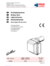
Installation, use and maintenance instructions
Kerosene and gas oil burners
One stage operation
CODE MODEL TYPE
8099085 SIME MACK 1 EI 515 T3K
8099090 SIME MACK 2 EI 515 T5K

4

2764
1
INDEX
1. BURNER DESCRIPTION
Kerosene and gas oil burners with one stage working. For gas oil working, the fuel temperature must be
higher than 10 °C.
1.1 BURNER EQUIPMENT
Flange with insulating gasket. . . . . . No. 1 Screws and nuts for flange to be fixed to boiler . . No. 4
Screw and nuts for flange . . . . . . . . No. 1 Flexible oil pipe with nipple. . . . . . . . . . . . . . . . . . No. 1
Cable grommet . . . . . . . . . . . . . . . . No. 1 7 pin plug . . . . . . . . . . . . . . . . . . . . . . . . . . . . . . . No. 1
By-pass screw . . . . . . . . . . . . . . . . . No. 1
1. BURNER DESCRIPTION. . . . . . . . . . . . . 1
1.1 Burner equipment . . . . . . . . . . . . . . . . . . 1
2. TECHNICAL DATA . . . . . . . . . . . . . . . . . 2
2.1 Technical data . . . . . . . . . . . . . . . . . . . . . 2
2.2 Overall dimensions . . . . . . . . . . . . . . . . . 2
2.3 Working fields . . . . . . . . . . . . . . . . . . . . . 2
3. INSTALLATION . . . . . . . . . . . . . . . . . . . . 3
3.1 Boiler fixing . . . . . . . . . . . . . . . . . . . . . . . 3
3.2 Hydraulic systems . . . . . . . . . . . . . . . . . . 4
3.3 Electrical wiring . . . . . . . . . . . . . . . . . . . . 5
4. WORKING . . . . . . . . . . . . . . . . . . . . . . . 6
4.1 Combustion adjustment. . . . . . . . . . . . . . 6
4.2 Nozzles recommended . . . . . . . . . . . . . . 7
4.3 Maintenance position . . . . . . . . . . . . . . . 7
4.4 Electrodes setting . . . . . . . . . . . . . . . . . . 7
4.5 Air damper adjustment . . . . . . . . . . . . . . 7
4.6 Pump pressure . . . . . . . . . . . . . . . . . . . . 8
4.7 Burner start-up cycle. . . . . . . . . . . . . . . . 8
5. MAINTENANCE . . . . . . . . . . . . . . . . . . . 8
6. FAULTS / SOLUTIONS . . . . . . . . . . . . . . 9
■CE Certification No.: 0036 0312/01 (515 T3K) – 0036 0331/02 (515 T5K), as 92/42/EEC.
■The burner meets protection level of IP 40, EN 60529.
■Burner with CE marking in conformity with EEC directives: EMC 89/336/EEC, Low Voltage 73/23/EEC,
Machines 98/37/EEC and Efficiency 92/42/EEC.
1– Pump
2– Control-box
3– Reset button with lock-out lamp
4– Hydraulic jack with air-damper
5– Screws fixing air-damper
6– Flange with insulating gasket
7– Cable grommet
Fig. 1
D6272
1
2
3
4
6
5
5
7

2764
2
2. TECHNICAL DATA
2.1 TECHNICAL DATA
◆
Gas oil is not permitted on low level discharge of flue gas products.
2.2 OVERALL DIMENSIONS
2.3 WORKING FIELDS
(as EN 267
)
Model MACK 1 EI MACK 2 EI
Output - Thermal power
(with air at 20°C)
2 – 3.2 kg/h 2.8 – 3.9 kg/h
24 – 38.3 kW 33.6 – 46.6 kW
Fuel Kerosene, viscosity 1.6 – 6 mm
2
/s at 20 °C
(Hi = 11.97 kWh/kg)
Gas oil, viscosity 4 – 6 mm
2
/s at 20 °C
◆
(Hi = 11.86 kWh/kg)
Electrical supply Single phase,
~
50Hz 230V
±
10%
Motor Run current 0.7A – 2850 rpm – 298 rad/s
Capacitor 4
µ
F
Ignition transformer Secondary 8 kV – 16 mA
Pump Kerosene, maximum pressure 10 bar (145 psi)
Gas oil, maximum pressure 14 bar (203 psi)
Absorbed electrical power 0.13 kW
Flange Burner
285 86 230
130
=
16
45°
ø 89
249
11
186
D6262
=
91
72 72
150
45°
180
D5908
Pressure in the combustion
chamber – mbar
Fuel output – kg/h
Thermal power – kW
D6289 22
1.0
0
0.4
0.2
0.6
0.8
1.8 2 2.2 2.4 2.6 2.8 3 3.2 3.4 3.6 3.8 4
26 30 34 38 42 46
MACK 1 EI MACK 2 EI

2764
3
3. INSTALLATION
THE BURNER MUST BE INSTALLED IN CONFORMITY WITH LEGISLATION AND LOCAL STANDARDS.
3.1 BOILER FIXING
➤
Put on the flange (1) the screw and two nuts, (see fig. 2).
➤
Widen, if necessary, the insulating gasket holes (5).
➤
Fix the flange (1) to the boiler door (4) using screws (2) and
(if necessary)
the nuts (3)
interposing the
insulating gasket (5)
, (see fig. 3).
Fig. 2
E9132
1
1
E9131
Fig. 3 43
2
2
5

2764
4
3.2 HYDRAULIC SYSTEMS
The burner is designed to allow entry of the flexible oil-lines on either side of the burner.
■
Check periodically the flexible pipes conditions.
Using kerosene, they have to be replaced at least
every 2 years.
H
= difference of level
L
= Max. lenght of the suction line
I.D.
= Interminal diameter of the oil pipes
PRIMING PUMP:
On the system in fig. 5 it is sufficient to loosen the suction gauge
connection (6, fig. 4) and wait until oil flows out.
On the systems in fig. 6 and 7 start the burner and wait for the priming.
Should lock-out occur prior to the arrival of the fuel, await at least 20 seconds
before repeating the operation.
T
he pump suction should not exceed a maximum of 0.4 bar (30 cm Hg).
Beyond this limit gas is released from the oil. Oil pipes must be completely tight.
In the vacuum systems (fig. 7) the return line should terminate within the oil tank
at the same level as the suction line. In this case a non-return valve is not re-
quired. Should however the return line arrive over the fuel level, a non-return
v
alve is required.
T
his solution however is less safe than previous one, due to the possibility of
leakage of the valve.
■
It is necessary to install a filter on the fuel supply line.
The standard filter code 6276200 and that one with recirculation
code 6276201 are available on request.
■
The pump is designed to allow working with one pipe.
In order to obtain two pipes working it is necessary to unscrew
the return plug (2), screw the by-pass screw (3) and then screw
again the plug (2). (See fig. 4).
■
In the two pipes systems, before starting the burner make sure
that the return pipe-line is not clogged. An excessive back pres-
sure would cause the damage of the pump seal.
WARNING:
1 - Suction line
2 - Return line
3 - By-pass screw
4 - Gauge connection
5 - Pressure adjuster
6 - Suction gauge connection
7 - Oil valve
8 - Auxiliary pressure test point
Fig. 4
D5912 2
3
4
7
6
5
18
H
meters
L meters
I. D.
8 mm I. D.
10 mm
0.5
1
1.5
2
10
20
40
60
20
40
80
100
H
meters
L meters
I. D.
8 mm I. D.
10 mm
0
0.5
1
1.5
2
3
3.5
35
30
25
20
15
8
6
100
100
100
90
70
30
20
SYSTEM NOT
IN GERMANY
H
max. 4 m
max. 4 m
H
H
H
D6285
Fig. 6 Fig. 7
Fig. 5
H
max. 4 m
D6284
PERMITTED

2764
5
3.3 ELECTRICAL WIRING
TESTING
Check the shut-down of the
burner by opening the ther-
mostats.
CONTROL BOX
To remove the control-box
from the burner, loosen screw
(A, fig. 8) and pull to the arrow
direction, after removing all
components, the 7 pin plug
and earth wire.
NOTES:
– Wires of min. 1 mm2 section.
(Unless requested otherwise by local standard
s
and legislation).
– The electrical wiring carried out by the installer
must be in compliance with the rules in force in the
Country.
DO NOT EXCHANGE NEUTRAL WITH PHASE
WARNING
ACCESS TO THE PHOTORESISTANCE
(See fig. 9)
The photoresistance is fitted directly into the con-
trol-box
(underneath the ignition-transformer)
on a
plug-in support.
Ignition
transformer
Fig. 9
E9102
Photoresistance
CARRIED-OUT IN THE FACTORY
7 pin plug
7 pole socket
Black
White
Blue
Capacitor
Burner-earth
T6A
CONTROL BOX
554SE
~ 50Hz 230V
D1846
Photoresistance
Oil valve
Hour counter
(230V - 0.1A max.)
Limit thermostat Remote lock-out signal
(230V - 0.5A max.)
Ignition
electrodes
LNPE
Motor
Main switch
Safety thermostat
Fig. 8
E9157 A

2764 6
4. WORKING
4.1 COMBUSTION ADJUSTMENT
In conformity with Efficiency Directive 92/42/EEC the application of the burner on the boiler, adjustment and test-
ing must be carried out observing the instruction manual of the boiler, including verification of the CO and CO2
concentration in the flue gases, their temperatures and the average temperature of the water in the boiler.
To suit the required appliance output, fit the proper nozzle, then adjust the pump pressure and the air damp-
er opening in accordance with the following table.
■ADJUSTMENTS CARRIED OUT IN FACTORY FOR SIME BOILERS
The values shown in the table are measured on a SIME boiler (as per EN 267).
They refer to 12.5% CO2 at sea level and with kerosene and gas oil and room temperature of 20 °C.
Table A
▲Burner adjustments carried out in factory.
In case of matching with a boiler or fuel different than factory adjustment, set the burner according to
the values indicated in the table.
■APPROXIMATE ADJUSTMENTS FOR INSTALLATION ON OTHER BOILERS
The values shown in the table are measured on a CEN boiler (as per EN 267).
They refer to 12.5% CO2 at sea level and with kerosene and gas oil and room temperature of 20 °C.
BOILER BURNER Nozzle Pump
pressure Burner
output Air damper
adjustment
Code Model GPH Angle bar kg/h ± 4% Set-point
Kerosene
Rondò-Estelle 3 8099085 MACK1 EI 0.75 60° W 7 2.1 3.7
Rondò-Estelle 4 ▲1.00 60° W 8 3 3
Rondò-Estelle 5 ▲8099090 MACK2 EI 1.25 60° W 8 3.7 3.8
Gas oil
Rondò-Estelle 3
Rondò-Estelle 4 8099085 MACK1 EI 0.75 60° W 11.5 2.9 2.9
Rondò-Estelle 5 8099090 MACK2 EI 0.85 60° W 13 3.6 3.8
BURNER
MODEL Nozzle Pump
pressure Burner
output Air damper
adjustment
GPH Angle bar kg/h ± 4% Set-point
Kerosene
MACK 1 EI
0.65 60° 8.5 2.0 1.5
0.75 60° 8 2.2 1.8
0.85 60° 8 2.5 2.2
1.00 60° 8 3.0 2.8
1.10 60° 7.5 3.2 3.5
MACK 2 EI
1.00 60° 7 2.8 2.2
1.10 60° 8 3.2 2.5
1.25 60° 8 3.7 3.2
1.25 60° 9 3.9 3.7
Gas oil
MACK 1 EI
0.50 70° 12 2.0 1.7
0.55 60° 12 2.2 1.9
0.60 60° 12 2.4 2.1
0.65 60° 12 2.6 2.4
0.75 60° 13.5 3.2 3.2
MACK 2 EI
0.65 60° 13 2.8 2.2
0.75 60° 12 3.0 2.5
0.85 60° 12 3.4 3.0
0.85 60° 14.5 3.9 3.7

2764 7
4.2 NOZZLES RECOMMENDED:
Monarchtype R - NS; Delavan type W-E
Steinen type H - Q ; Danfoss type H - S.
4.3 MAINTENANCE POSITION
Access to the combustion head, electrodes and noz-
zle, (see fig. 10).
➤Remove the burner out of the boiler, after loosing the
fixing nut to the flange.
➤Hook the burner to the flange (1), by removing the com-
bustion head (2) after loosing the fixing screws (3).
➤Remove the electrodes assembly (5) from the nozzle-
holder (4) after loosing its fixing screw (B, fig. 11).
➤Screw the nozzle (6).
4.4 ELECTRODES SETTING
4.5 AIR DAMPER ADJUSTMENT, (see fig. 12)
The mobile air damper (1) operated by the jack (2) assures the
complete opening of the air intake.
The regulation of the air-rate is made by adjusting the fixed air
damper (3), after loosing the screws (4).
When the optimal regulation is reached, screw tight the screws
(4) to assure a free movement of the mobile air damper (1).
The settings, indicated in the table (page 6), refer to the burner
with its cover fitted and combustion chamber with depression
zero. These regulations are purely indicative.
Each installation however, has its own unpredictable working
conditions: actual nozzle output; positive or negative pressure
in the combustion-chamber, the need of excess air, etc.
All these conditions may require a different air-damper setting.
E9155
2
54
1
3
6
Fig. 10
Before removing or assembling the
nozzle, loosen the screw (B, fig. 11)
and move the electrodes ahead.
ATTENTION Fig. 11
2 – 2.5 mm
4± 0.3 mm
IMPORTANT:
THESE DIMENSIONS
MUST BE OBSERVED
D5230 B
Fig. 12
4
3
D6286
4
12

2764 8
It is important to take account of the fact that the air output of the fan differs according to whether
the burner has its cover fitted or not. Therefore we recommended to proceed as follows:
➤ Adjust the air damper as indicated in the table.
➤ Mount the cover.
➤Check smoke number and CO2.
➤ Should it become necessary to modify the air output, remove the cover by loosening the screw, adjust
the air damper, remount the cover and finally recheck the smoke number.
4.6 PUMP PRESSURE:
The pump leaves the factory set for kerosene working, according to the value indicated in the table A (▲) at
page 6.
10 bar: maximum pressure for kerosene.
FOR GAS OIL INCREASE PRESSURE
12 bar: pressure suitable for gas oil in most cases.
14 bar: improves flame retention; it is therefore suitable for ignitions at low temperatures.
4.7 BURNER START-UP CYCLE
Lock out is indicated by a lamp on the control box (3, fig. 1, page 1).
5. MAINTENANCE
The burner requires periodic maintenance carried out by a qualified and authorised technician in conformity
with legislation and local standards.
Maintenance is essential for the reliability of the burner, avoiding the excessive consumption of fuel and
consequent pollution.
Before carrying out any cleaning or control always first switch off the electrical supply to the
burner acting on the main switch of the system.
THE BASIC CHECKS ARE:
➤Check that there are not obstructions or dents in the supply or return oil pipes.
➤Clean the filter in the oil suction line and in the pump.
➤Clean the photoresistance, (see fig. 9, page 5).
➤Check for correct fuel consumption.
➤Replace the nozzle (see fig. 10, page 7) and check the correct position of electrodes (fig. 11, page 7).
➤Clean the combustion head in the fuel exit area, on the diffuser disc.
➤Leave the burner working without interruptions for 10 min. and set rightly all the components stated in
this manual. Then carry out a combustion check verifying:
●Smoke temperature at the chimney; ●Content of CO2 (%); ●Content of CO (ppm);
●Smoke value according to opacity smokes index according to Bacharach scale.
Lock-out due to failure to light
B
Normal
D5029
~12s
Thermostat
Green led and motor
Ignition transformer
Oil valve
Flame
Lock-out lamp ~12s 5s
B

2764 9
6. FAULTS / SOLUTIONS
Here below you can find some causes and the possible solutions for some problems that could cause a fail-
ure to start or a bad working of the burner.
A fault usually makes the lock-out lamp light which is situated inside the reset button of the control box
(3, fig. 1, page 1).
When lock out lamp lights the burner will attempt to light only after pushing the reset button. After this if the
burner functions correctly, the lock-out can be attributed to a temporary fault.
If however the lock out continues the cause must be determined and the solution found.
WARNING
The manufacturer cannot accept responsibility for any damage to persons, animals or property due to error in
installation or in the burner adjustment, or due to improper or unreasonable use or non observance of the
technical instruction enclosed with the burner, or due to the intervention of unqualified personnel.
FAULTS POSSIBLE CAUSES SOLUTION
The green led on
the control box is
off and the burner
does not start.
Lack of electrical supply.
Check presence of voltage in the
L1 - N clamps of the 7 pin plug.
Check the conditions of the fuses.
Check that safety thermostat is not
lock out.
The connections in the control box are
wrongly inserted. Check and connect completely all the
plugs.
The green led on
the control box is
on and the burner
remains in the pre-
purge phase.
The photoresistance sees false light. Eliminate the light.
Burner runs nor-
mally in the pre-
purge and ignition
cycle and locks out
after 5 seconds ca.
The photoresistance is dirty. Clear it.
The photoresistance is defective. Change it.
Flame moves away or fails.
Check pressure and output of the fuel.
Check air output.
Change nozzle.
Check the coil of solenoid valve.
Burner starts with
an ignition delay.
The ignition electrodes are wrongly
positioned. Adjust them according to the
instructions of this manual.
Air output is too high. Set the air output according to the
instructions of this manual.
Nozzle dirty or worn. Replace it.

Fonderie Sime S.p.A. - via Garbo, 27 - 37045 Legnago (Vr) - Italy
Tel. +39/0442 631111 - Export Division fax number +39/0442 631293 - Sime Service fax number +39/0442 631292
/