Page is loading ...

WASP SERIES CONTROL CENTER WITH MCD TECHNOLOGY
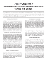
PLUG MODULE INTO COMM PORT
TELEMETRY COMMISSIONING AND OPERATION
The advanced integrated circuitry of the Service Pro WASP control center simplifies the Singulair installation, improves
system performance and allows for communication with the Service Pro website. The integrated circuitry continually monitors
both motor over current and under current conditions and minimizes nuisance alarm conditions through an automatic restart
feature. To reduce unnecessary service calls, the control center shuts down the Singulair aerator in the event of an over
current or an under current alarm condition, or the effluent pump in the event of an over current condition. The Service Pro
WASP control center illuminates the appropriate alarm light and begins an automatic two hour aerator or pump restart
attempt sequence before activating the audible alarm and telemetry system.
Service Pro WASP control centers are equipped with an automatic telemetry system designed to communicate through a toll
free telephone number, Internet connection or cellular connection. In the event of an alarm condition that cannot be corrected
by the control center’s self-diagnostic sequence, the telemetry system contacts the Service Pro remote monitoring center.
The monitoring center identifies the alarming control center and logs the time that the message was received and the specific
alarm condition reported. The monitoring center then automatically updates the website and notifies the responsible Norweco
distributor or service provider by email, fax or telephone. In addition to documenting alarm conditions, the website tracks the
date, time and duration of service visits, service contract renewals and maintains a complete database for every Singulair
system registered. Access to the information is password protected and available to licensed distributors, sponsored service
providers, health departments and system owners.
These instructions are not intended to be a complete electrical, telecommunication or network system installation reference.
Telecommunication and network system policies as well as electrical code requirements vary according to geographic area.
Consult your local policies and regulations prior to installing the Service Pro WASP control center. Refer to the Electrical
Wiring and Control Center Installation instructions for additional details.
INSTALLATION OF TELEMETRY MODULE
The Service Pro WASP control center is compatible with
phone, Internet and cellular communication modules. If a
telephone connection will be utilized, a telephone line must
be installed unspliced from the telephone box to the control
center. Before installing the telephone line, familiarize
yourself with the equipment and policies of the local telephone
service provider. The Service Pro WASP control center is
not compatible with digital telephone service. With DSL
Internet service, a DSL filter will need to be connected to the
telephone jack to insure proper operation. If a telephone
line is not available, one will need to be installed or an Internet
or cellular communication module should be utilized. If an
Internet connection will be utilized, a network cable must be
installed from the switch or router that distributes Internet
service in the home.
The following steps must be performed to complete the
installation of the telemetry module:
1. Attach the telemetry module to the right interior side of
the enclosure with the Velcro strips provided.
2. If a telephone module is being installed, connect the
ground wire from the module to the “INCOMING” power
terminal marked “G”.
3. Plug the black connector from the telemetry module
into the port marked “COMM” on the control center.
4. Plug the telephone or network line into the appropriate
jack on the telemetry module.
INSTALL TELEMETRY MODULE

©MMXVI NORWECO, INC. NORWALK, OHIO U.S.A.
MANUFACTURED BY
NORWECO, INC.
NORWALK, OHIO
U.S.A. 44857
www.norweco.com
SERVICE PRO
®
WASP CONTROL CENTER INSTRUCTIONS
5. Conduct the normal Singulair system service as outlined
in the “Singulair System Service Manual” and any other
service that may be needed on auxiliary equipment.
To record the end of each service visit:
6. Press and hold in the “ALARM RESET” button for at
least 5 seconds.
7. After the alarm lights on the control center illuminate
and the alarm buzzer sounds, release the “ALARM
RESET” button. The display will read ‘ALARM TEST’.
Testing of the alarm lights and alarm buzzer is now
complete.
8. The panel now calls the remote monitoring center to
record the time the service visit ended.
9. The display will read ‘CALL SUCCESSFUL’ when the
call is complete.
Upon completion of service work, fill out the door hanger
service record and deliver it to the homeowner or hang the
service record form on the door.
SERVICE PRO WEBSITE & REGISTRATION
The telemetry system is engineered to interface with the
Service Pro monitoring center. The Service Pro monitoring
center allows online access to Singulair wastewater
treatment system records. Records generated by the
Service Pro control center (heartbeat record, alarm
conditions, service records) can be accessed at
www.servicepromcd.com. For access to the website,
contact your local distributor or Norweco, Inc.
Permanent record retention and remote monitoring of the
Singulair system will begin when the following steps have
been completed:
The “Add New Subscriber” section of the website has
been completed by the Singulair distributor or service
provider
The system is started up and the Service Pro control
center is commissioned
Three copies of the signed Service Pro Subscriber
Monitoring Agreement are received by Norweco
A control center can be commissioned either before or after
the new account has been registered with the Service Pro
monitoring center. However, if the commissioning step is
performed first, the registration of the new account must be
completed within 30 days of commissioning.
COMMISSIONING THE TELEMETRY SYSTEM
The commissioning process electronically registers the
Service Pro WASP control center with the web based remote
monitoring center at www.servicepromcd.com. Once
commissioned, the panel is capable of automatically placing
calls to the remote monitoring center. First, turn the breaker
in the household power panel to the on position and verify
that the control breaker in the Service Pro WASP control
center is in the off position. Next, press the “ALARM RESET”
button and keep it depressed while turning the control circuit
breaker in the Service Pro WASP panel to the “on” position.
Continue to hold in until the display reads ‘LET GO TO
COMMISSION’. Release the “ALARM RESET” button. The
display will read ‘CALLING…’ indicating the Service Pro
WASP control center is calling the remote monitoring center
to commission the panel. When the display reads ‘CALL
SUCCESSFUL’, the unit has been commissioned. If
commissioning is unsuccessful, the display will indicate why
the communications failed. Correct the problem and
recommission the panel.
Conduct an alarm test to verify the Service Pro WASP control
panel has been successfully commissioned. To conduct
an alarm test, press and hold in the “ALARM RESET” button
for at least 5 seconds. After the alarm lights on the control
center illuminate and the alarm buzzer sounds, release the
“ALARM RESET” button. The display will read ‘ALARM TEST’
and the panel will call the remote monitoring center to record
the manual alarm test. If the display reads ‘CALLING…’
during the alarm test, this confirms that the panel has been
successfully commissioned. Otherwise, it will be necessary
to recommission the panel.
RECORDING SERVICE VISITS AND TESTING ALARMS
Time spent on a service visit is important to all parties
involved. This includes, but is not limited to builders, licensed
distributors, installers, service providers, regulatory personnel
and homeowners. The control center will record the duration
of each service visit and provide a permanent record (on the
Service Pro website) of the time spent at each service visit.
To record the beginning of each service visit:
1. Press and hold in the “ALARM RESET” button for at
least 5 seconds.
2. After the alarm lights on the control center illuminate
and the alarm buzzer sounds, release the “ALARM
RESET” button. The display will read ‘ALARM TEST’.
Testing of the alarm lights and alarm buzzer is now
complete.
3. The panel now calls the remote monitoring center to
record the time the service visit started.
4. The display will read ‘CALL SUCCESSFUL’ when the
call is complete.
/