Page is loading ...

Installation of the aerator and Bio-Kinetic system should take place when the Singulair Green system is ready for
start-up. Refer to the Bio-Kinetic System Installation instructions for additional details regarding the installation of the
Bio-Kinetic system. Your delivery truck driver should have instructed the contractor or owner to contact your oce and
make arrangements for equipment installation to occur after the home is occupied and the sanitary sewer is in use.
The Bio-Kinetic system is installed in the nal clarication chamber of the Singulair Green tank. This unique device
accomplishes tertiary treatment, ow equalization and, if required by local regulations, euent disinfection and dechlorination
in one compact assembly. The Bio-Kinetic system is recommended for use in direct o-lot discharge applications and any
other application where extremely high quality euent is desirable. Installation of the Bio-Kinetic system can take place
as soon as the tank is ready for storage or immediately after the tank is installed in a prepared excavation.
Drain and ll valves built into the Bio-Kinetic system allow it to be installed within the Singulair Green tank any time before
or after the tank has been set. This allows faster Singulair Green system installation and less time at the installation site.
When installing the Bio-Kinetic system before tank delivery, make sure the tank is stored in a level position to avoid stress
on the receiving ange, the Bio-Kinetic discharge ange or to prevent damage to the outer chamber lter media.
BIO-KINETIC
®
SYSTEM PRE-INSTALLATION CHECKLIST
All chambers of the Singulair Green tank should be full to the ow line with clean hold down water as soon as the tank is
placed in the excavation and backlling is complete. When the owner calls for start-up, ask him to check the liquid level in
the Singulair Green system. If the liquid level has not reached the outlet invert, have the owner add clean water until full.
The service vehicle should be fully stocked, including the Singulair Tool Kaddy, Bio-Kinetic lubricant,
Blue Crystal disinfecting tablets and Bio-Neutralizer dechlorination tablets.
Make sure the proper model of Bio-Kinetic system for the installation is in the service vehicle. The
Bio-Kinetic system may be supplied with or without Blue Crystal and Bio-Neutralizer chemical feed systems.
Therefore, check your order and Distributor Service and Warranty Record Card carefully to be sure you have selected
the proper Bio-Kinetic system with the correct service cover, ow distribution deck and feed tube(s) and that it is properly
labeled for the correct model Singulair Green system.
PREPARING THE SINGULAIR GREEN TANK
1. The Bio-Kinetic system mounting riser should be used
for access to the clarication chamber. Additional
extension risers may be added as necessary to reach
nished grade.
2. The Bio-Kinetic system should only be installed in a
mounting riser with a sealed access cover above it.
All mounting risers and covers must be in place before
backlling the tank to prevent ll material from entering
the Singulair Green tank. The top of each access cover
must be located 3" to 6" above nished grade. Check
to be sure that a pretreatment tee is installed in the
opening in the pretreatment/aeration chamber wall.
3. Check to be sure that a Bio-Static sludge return
is properly installed in the opening in the aeration/
clarication chamber wall.
4. The Singulair Green tank should be lled with clean
water. The water should be free of dirt, mud, leaves, grit,
oils or other materials that might possibly interfere with
operation of the system. The tank should be lled with
BIO-KINETIC SYSTEM
AUTOMATIC DRAIN AND FILL VALVES
SINGULAIR GREEN
®
BIO-KINETIC
®
WASTEWATER TREATMENT SYSTEM
INSTALLATION OF THE BIO-KINETIC
®
SYSTEM

MANUFACTURED BY
NORWECO, INC.
NORWALK, OHIO
U.S.A. 44857
www.norweco.com
©MMXVIII NORWECO, INC. NORWALK, OHIO U.S.A.
INSTALLATION THE OF BIO-KINETIC
®
SYSTEM (Cont.)
MOLDED LOCKING SLOTS
water immediately after backlling has been completed
to prevent damage to the Singulair Green tank. The
aeration and clarication chambers will both be lled
if the hose is installed in the aeration chamber access
opening. The pretreatment chamber should be lled
separately through its access opening.
5. Inuent and euent sewer lines must be installed
and connected to the system as soon as it is set and
before backlling to prevent entry of mud or debris.
Follow the procedures outlined in the Singulair Green
Tank Delivery and Setting instructions when backlling
the installation. Failure to follow proper backlling
procedure may result in damage to the tank and will
void the Singulair Green warranty.
6. When a Singular Green system is being installed to
replace a failed onsite wastewater treatment system,
the old septic tank need not be abandoned. However,
be sure the Singulair Green system is installed
downstream of the old septic tank and that the entire
obsolete system is completely pumped and cleaned
before the Singulair Green tank is installed. If the
owner prefers, the obsolete system may be totally
removed or lled in and abandoned in the ground.
7. Check to see that roong down spouts, footer drains,
sump pump piping or garage and basement oor drains
are not connected to the sanitary sewer. The Singulair
Green system may not operate properly if hydraulic
ows greatly exceed the rated treatment capacity. If the
facility is equipped with a water softener, locate the
backwash discharge line. The backwash line must not
be connected to the Singulair Green system.
BIO-KINETIC SYSTEM INSTALLATION PROCEDURE
Remove the Bio-Kinetic system from the shipping carton.
Lift o the Bio-Kinetic system service cover and set it
aside. Rotate the round, black locking lugs inward to allow
installation.
The Bio-Kinetic system discharge ange must engage
the plastic receiving ange that has been installed in the
outlet of the Singulair Green tank. Carefully examine the
condition of the outlet coupling and receiving ange. Any
residue or debris that has accumulated in the grooves of
the receiving ange must be removed and the grooves
and face of the receiving ange should be wiped clean.
Use the swab tool to apply a liberal amount of Bio-Kinetic
lubricant to the entire face of the receiving ange and the
inside of the grooves. Apply the lubricant evenly until all
interior surfaces of the receiving ange and the grooves are
thoroughly coated. Locate the gasketed discharge ange
assembly installed in the outlet of the Bio-Kinetic system.
Check to make sure that the assembly is tight and fully
engages the discharge opening of the Bio-Kinetic system.
Using the swab tool, apply a liberal amount of lubricant to
the exterior surfaces of the gasketed discharge ange.
Apply the lubricant evenly over the entire face of both sides
and along the edges of the discharge ange.
CAUTION: Bio-Kinetic lubricant has been specially
formulated. Use of other lubricants, especially
petroleum based lubricants, can cause degradation
of the rubber components and will void the warranty.
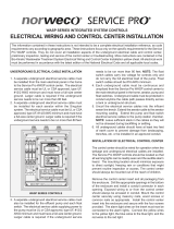
SELF FILL VALVE
Use the lifting tool to lower the Bio-Kinetic system into
the mounting riser. Be careful to align the discharge ange
with the receiving ange installed in the outlet of the tank.
The Bio-Kinetic system is equipped with a pressure sensitive
valve to aid in the lling process for new systems that are not
yet lled and the draining process during service or removal.
The ll valve is engineered to open when the pressure
outside the Bio-Kinetic system reaches 16" of head. When
the tank water level reaches 16" on the outer chamber of an
empty Bio-Kinetic system, the ll valve will open. The valve
will remain open until the water level inside the lter reaches
4" below the water level outside the lter. At this point, the
valve will close. For instructions on the drain valve system,
refer to “Clarication Chamber and Bio-Kinetic Service.”
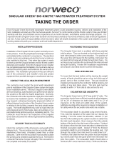
Carefully guide the system through the center of the opening
using the lifting tool. Be sure to maintain the Bio-Kinetic
system in a vertical position. If tilted, the system could rub
the edge of the opening and be damaged. NOTE: Use the
viewing port to be sure proper alignment and engagement
of the outlet connection takes place. The discharge ange

BUBBLE MUST REST BETWEEN THE TWO LINES
LOCKING DOWN THE BIO-KINETIC SYSTEM
CHECK FOR PROPER ALIGNMENT
SINGULAIR GREEN
®
BIO-KINETIC
®
INSTALLATION OF THE BIO-KINETIC
®
SYSTEM (Cont.)
must engage the top of the receiving ange.
Continue to lower the system until the discharge ange
fully engages the receiving ange and the top collar of the
Bio-Kinetic system rests on the ledge of the clarication
chamber access opening. To conrm that the discharge
ange and receiving ange are fully engaged, look through
the viewing port in the top collar. Use the locking lug tool
to twist each of the round, black locking lugs clockwise, so
that each locking lug is positioned directly into the molded
locking slots of the mounting riser.
PLACING THE BIO-KINETIC SYSTEM ON LINE
Locate the level indicator mounted above the outlet of
the Bio-Kinetic system ow distribution deck. The bubble
should be resting squarely between the two lines in the
clear plastic case. If the location of the bubble indicates
the system is not installed in a level position, the ow
distribution deck should be leveled using the four
adjustment lugs provided for this purpose. With the ratchet
drive, extension and
7
/
16
" socket from the Tool Kaddy,
turn each of the adjustment lugs the minimum amount
necessary for the bubble to rest squarely between the
two lines in the clear plastic case. Leveling of the ow
distribution deck is essential for proper operation of the
ow equalization ports, chemical feed tubes and euent
weir within the Bio-Kinetic system.
The system service cover can now be placed into position.
Install the cover, handle side up, aligning the four holes
in the cover with the four locking lug bolts. Be sure the
optional chlorination and dechlorination feed tube access
openings are in the proper position. The cover will come
to rest on the collar of the Bio-Kinetic system. There is no
need to add fasteners to the locking lug bolts.
If the installation requires a Blue Crystal disinfection
system, the chlorine feed tube opening in the service
cover must be positioned on the inlet side of the system
nearest the aerator mounting riser. Before handling
Blue Crystal disinfecting tablets, carefully read the container
label and the “Warning” section of these instructions. To
ll the chlorine feed tube, remove the cap, hold the tube
(open end down) with one hand and insert Blue Crystal
WASTEWATER TREATMENT SYSTEM

MANUFACTURED BY
NORWECO, INC.
NORWALK, OHIO
U.S.A. 44857
www.norweco.com
©MMXVIII NORWECO, INC. NORWALK, OHIO U.S.A.
disinfecting tablets, one tablet at time, until the tube is lled.
Each tablet must lie at in the stack. When the feed tube
has been completely lled, replace the cap. Twist the cap
clockwise until it locks securely into position on the chlorine
feed tube. Install the feed tube, slotted end down, through
the plastic collar molded into the top of the Bio-Kinetic
system service cover. The feed tube will begin to engage
the round recess in the ow distribution deck. Rotate the
chlorine feed tube clockwise until it locks into position.
NOTE: The chlorine feed tube must always be installed
through the mounting collar nearest the aerator mounting
riser. If the installation requires disinfection and
dechlorination, there will be two openings in the protective
cover. The dechlorination feed tube must be installed
nearest the system outlet.
WARNING
Blue Crystal disinfecting tablets are a strong oxidizing agent
and highly corrosive. Tablets should be stored in a cool, dry,
well-ventilated area away from combustible materials such
as paper, petroleum products, chemicals, rags or cardboard.
Contact with other liquids or chemicals may cause re.
Improper use of this product may cause personal injury or
property damage. Always wear rubber gloves and either
safety goggles or a face shield when handling Blue Crystal
disinfecting tablets or working with the chlorine feed tube.
Keep tablets out of the reach of children, as they can cause
skin and eye damage, irritate the nose and throat, and may
be fatal if swallowed. If on skin, wash with plenty of soap and
water for fteen minutes, call a doctor if irritation persists. If
swallowed, immediately drink large quantities of water, do
not induce vomiting, avoid alcohol and get medical attention
immediately. If inhaled, immediately remove victim to fresh
air. In the case of re, apply liberal quantities of water. It
INSTALLATION OF THE BIO-KINETIC
®
SYSTEM (Cont.)
BLUE CRYSTAL AND BIO-NEUTRALIZER
FEED TUBE INSTALLATION
is a violation of Federal law to use Blue Crystal tablets in
a manner inconsistent with the instructions printed on the
storage container label.
If the installation requires a Bio-Neutralizer dechlorination
system, the Bio-Kinetic system will be supplied with a
dechlorination feed tube. Before handling Bio-Neutralizer
dechlorination tablets, carefully read the container label
and the “Warning” section of these instructions. To ll
the dechlorination feed tube, remove the cap, hold the
tube (open end down) with one hand and insert the
Bio-Neutralizer dechlorination tablets, one tablet at a time,
until the tube is lled. Each tablet must lie at in the stack.
When the tube has been completely lled, replace the cap.
Twist the cap clockwise until it locks securely into position
on the dechlorination feed tube. Insert the dechlorination
feed tube, slotted end down, into the mounting collar closest
to the system outlet. The bottom of the tube must come to
rest evenly on the oor of the ow deck.
WARNING
Bio-Neutralizer dechlorination tablets must be stored in
a cool, dry place away from acids and oxidizers. Do not
allow Bio-Neutralizer tablets to come into contact with
chlorine tablets. Although not rated a hazardous material
by the USEPA, exercise caution when handling and wash
skin thoroughly with soap and water if contact occurs.
Inspect the Bio-Kinetic system to verify that all four locking
lugs are fully engaged into the molded locking slots in the
riser, the moisture vapor shield is properly installed over
the four locking lug bolts and the feed tubes are properly
installed. Reinstall the Bio-Kinetic system access cover
on the clarier riser. Secure the access cover to the riser
using the fasteners provided. Now proceed with the steps
outlined in the Singulair Green System Final Check and
System Start-Up instructions. DANGER: Make sure the
system access cover is in good condition and securely
installed on the mounting riser. Never allow access
risers to be left uncovered or partially covered. Failure
to secure access covers and safety nets could result
in bodily injury, illness or death. Riser safety nets are
available from Norweco for concrete or plastic risers.
SERVICING THE BIO-KINETIC SYSTEM
Each installation equipped with the Bio-Kinetic system
should be inspected and serviced during each six-month
service inspection. Refer to the Bio-Kinetic System Service
instructions for service and recordkeeping procedures.
/