Page is loading ...

CONTROL CENTER WITH MCD TECHNOLOGY
QUICK START GUIDE
PRE-START UP AND INSTALLATION CHECKLIST
A. Turn off breaker at household power panel.
B. Turn off the recessed power switch on lower right of
Service Pro control center.
C. Gently remove Service Pro panel insert
from the enclosure. CAUTION: Do not
pull out too far - it may loosen the wire
connections.
D. Be sure phone line or network cable is
plugged in.
E. Check four yellow wire nuts to ensure
tight connection.
F. Check auxiliary alarm wiring (if any) to
be sure the terminals are properly
crimped and plugged in at the correct
location(s).
G. Check conduit openings to be sure they
are duct sealed to prevent corrosive
vapors from entering the enclosure.
H. Check to ensure phone line or network
cable is properly installed. On outdoor
installations, phone line or network
cable must be outdoor rated and, for
NEMA 3R compliance,
1
/
8
" knockout
hole in bottom of control enclosure
must be opened to vent moisture from
the enclosure.
I. Gently reinstall insert into control
enclosure. Be sure insert is fully seated.
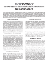
PANEL COMPONENT IDENTIFICATION AND FUNCTION
There are a total of ten separate components visible on the
control panel. See sketch above.
Top left on panel - Green power light
Should always be lit when breaker in household
panel is turned on and Service Pro recessed power
switch is turned on.
Middle left on panel - Yellow communication light
Lit only when panel is communicating.
Bottom left on panel - Red aerator light
Lit only when aerator has malfunctioned.
Top right on panel - Red auxiliary input light (AUX 1)
Lit only when optional treatment device number
one needs service.
Middle right on panel - Red auxiliary input light (AUX 2)
Lit only when optional treatment device number
two needs service.
Bottom right on panel - Red auxiliary input light (AUX 3)
Lit only when optional treatment device number
three needs service.
SERVICE PR
®
TNT
NETWORK
Flash 10 short
Top center on panel - Time clock. Not adjustable.
Factory preset. System cycles automatically one
hour on and one hour off.
Middle center on panel - Red alarm light
Not lit during normal operation. This light is used
to monitor system functions as follows:
Condition Light Flash Pattern
Successful
commissioning
Alarm test
Service visit start
Service visit end
Phone/network Flash 1 short, 1 long
cable not secure pause 3 sec. & repeat
Phone line in use Flash 2 short, 1 long
in home pause 3 sec. & repeat
Number called Flash 3 short, 1 long
is busy pause 3 sec. & repeat
Remote monitoring
error Flash 4 short, 1 long
Phone service pause 3 sec. & repeat
termination
Pane
l c
ommunication Flash 5 short, 1 long
error pause 3 sec. & repeat
Control failure Illuminate continuous
Aerator under Flash 2 short
current pause 3 sec. & repeat
Aerator open Flash 2 short
motor pause 3 sec. & repeat
Aerator over current Flash evenly until
Auxiliary input serviced
Bottom center on panel - Reset button
The reset button is used to perform a variety of
functions as follows:
Condition Function
Reset aerator Turns off alarm
and restart timed light and buzzer and
run cycle restarts aerator
Alarm test Actuates alarm light
and buzzer
Service visit begins Records start of
service call
Service visit ends Records end of
service call
Commission call Triggers call for
commissioning
Decommissioning Shuts off remote
monitoring feature
Silence alarms Shuts off alarm
buzzer and light
Lower right on panel - Recessed power switch
On/off selector switch for power to panel.
Flash 5 short

NORWECO, INC.
NORWALK, OHIO
U.S.A. 44857
www.norweco.com
QUICK START GUIDE (Cont.)
COMMISSIONING THE PANEL’S TELEMETRY SYSTEM
The commissioning process electronically registers the
Service Pro panel with the web based remote monitoring
center at www.servicepromcd.com. Once commissioned,
the panel is capable of automatically placing calls to the
remote monitoring center. First, turn the breaker in the
household power panel to the on position and verify that the
recessed power switch on the lower right of the Service Pro
control center is in the off position. Next, press the reset
button and keep it depressed while turning the recessed
power switch in the Service Pro panel to the on position.
Continue to hold in until the red light illuminates. Release
the reset button. The yellow light will come on indicating
the Service Pro control center is calling the remote monitoring
center to commission the panel. When the yellow light
goes out, the unit has been commissioned. If commissioning
is successful, the red alarm light (middle center) will flash 5
short flashes and stop. If commissioning is unsuccessful,
the alarm light will flash a pattern of short and long flashes
followed by a long pause and repeat of the pattern. Refer to
the table in item 8 on the previous page for troubleshooting
information. Conduct an alarm test to verify commissioning
was successful. If the yellow light does not illuminate during
the alarm test, recommission the panel. If a phone line will
be used for remote monitoring and the homeowner uses
DSL for Internet service, a communication error can occur
during commissioning. This can be resolved by installing a
DSL filter on the phone line going into the Service Pro panel.
If digital telephone service (VOIP) is used, an Internet
communications module should be used. Some VOIP
systems are not compatible with Service Pro panels equipped
with a telephone communications module.
RECORDING SERVICE VISITS AND TESTING ALARMS
Time spent on a service visit is important to all parties
involved. This includes, but is not limited to, builders,
licensed distributors, installers, sponsored service providers,
regulatory personnel and homeowners. The Service Pro
control center will record the duration of each service visit
and provide a permanent record (on the Service Pro website)
of the time spent at each service visit.
To record the beginning of each service visit:
1. Press and hold in the reset button for at least 5 seconds.
2. After the alarm light in the center of the panel flashes
and the alarm buzzer sounds, release the reset button.
The yellow light will turn on. Testing of the alarm light
and alarm buzzer is now complete.
3. The panel now calls the remote monitoring center to
record the time the service visit started.
4. The yellow light will turn off when the call is complete.
5. Conduct the normal Singulair system service as outlined
in the “Singulair System Product Manual” and any other
service that may be needed on auxiliary equipment.
To record the end of each service visit:
6. Press and hold in the reset button for at least 5 seconds.
7. After the alarm light in the center of the panel flashes
and the alarm buzzer sounds, release the reset button.
The yellow light will turn on.
8. The panel will call the remote monitoring center to record
the time the service visit ended.
Fill out the door hanger service record and deliver it to the
homeowner or hang the service record form on the door.
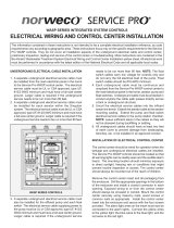
AUXILIARY EQUIPMENT IDENTIFICATION LABELS
Be sure to properly label all auxiliary equipment inputs. An
assortment of weather resistant, adhesive backed labels,
as shown here, has been preprinted and included with the
panel. Select the correct preprinted labels and install above
appropriate auxiliary lights on panel insert. Label unused
AUX inputs NOT IN USE. Extra labels may be used for
identification of individual components throughout the
wastewater facility. Use ball point pen only on blank labels
where needed. Do not discard extra labels while at jobsite.
WARNING: The Service Pro control center is designed to
monitor residential wastewater treatment equipment only.
Connection of household appliances or other unauthorized
equipment may damage equipment and void the warranty.
©MMXIII NORWECO, INC. NORWALK, OHIO U.S.A.
/