Audio Authority 1502 User manual

Category
Door intercom systems
Type
User manual
Series 1500
Intercom Systems
Patent D/528,534
Installer’s Reference Guide
2 Audio Authority
®
Series 1500 Installer’s Reference Guide
Audio Authority
®
Series 1500 Installer’s Reference Guide 3
Contents
Introduction 2
Component Overview 2
Cable Fabrication 2
Installation Overview
One-On-One System 3
Small Audio System 3
Audio/Video System 4
Installing Components
The Hub 5
The Counter Station 6
The Lane Station 7
Testing Your Installation 8
Troubleshooting Tips and
Common Issues 8
Hub Diagrams
Audio Hub (1509) 9
Audio/Video Hub (1510) 10
Expanding Capacity 11
Operator Instructions 12
1550 Field Setup Tool
System Calibration & Setup 13
Setup Menu Map 13
Example Conguration 15
The Memory Card
Memory Card Notes 16
Firmware Upgrade Procedure 16
Installing and Using the
Series 1500™ Intercom Systems
Series 1500
Intercoms enable clear two-way communications in
retail service businesses. Two-way video is integrated with high-
performance audio to provide a complete intercommunication solution
over a single Category 5e or 6 UTP cable. The versatile Model 1500
Counter Station, which can access up to 16 lanes, and the Model 1520
Lane Station can be connected directly to each other in a one-on-one
system, or multiples of each can be networked using a Model 1509
Hub for up to two-on-four audio performance or Series 1510 Hub for
multi-lane systems (See example diagrams on the following pages).
Series 1510 Hubs can support up to 8 Counter Stations on 16 lanes.
Counter Audio Station 1500
Counter Video Add-on 1502
2-on-4 Audio Hub 1509
4-on-4 Audio/Video Hub 1510
4-on-8 Audio/Video Hub 1511
8-on-12 Audio/Video Hub 1512
8-on-16 Audio/Video Hub 1513
(See page 11 for Hub configurations)
4-counter plug-in card 1515
4-lane plug-in card 1516
System plug-in card 1517
Lane Station 1520
Complete A/V Station 1522
Customer Video Add-On 1523
Surface-mount handset 1540
Flush-mount handset 1541
Wireless headset 1542
Wired headset 1543
Field Setup LCD 1550
Universal 1A Power Supply 571-013
Boom Microphone 631-026
External microphone kit 631-029
External 3”, 4 ohm speaker 631-030
3 Amp UL DC power supply 805-016
Tools and Supplies
Cat 5 network cable tester
RJ-45 plug crimping tool (Audio
Authority recommends EZ-RJpro
crimp tool)
Category 5e or 6 UTP cable and
RJ-45 terminations (Audio Authority
recommends EZ-RJ-45 connectors)
18mm open-end wrench
(for boom mic)
Model 1550 Field Setup LCD
Display Tool
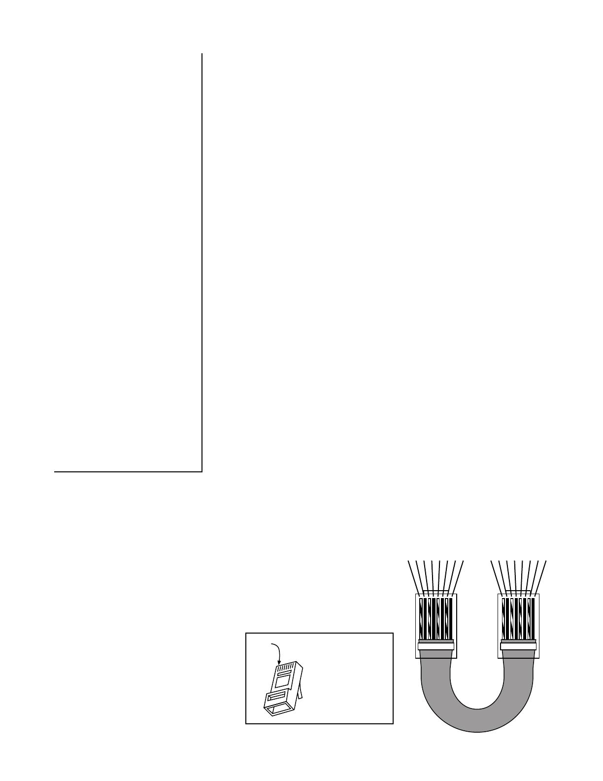
Terminate the ends of each cable
with RJ-45 modular plugs using
the EIA 568B pinout (paired 1-
2, 3-6, 4-5, and 7-8). Pre-made
network cables may also be used
for shorter runs. Test all cables
with a network cable tester.
Note: Cat 5e and Cat 6 are also
acceptable cable types.
Series 1500 System Components
5 WHITE / BLUE
7 WHITE / BROWN
6 GREEN
3 WHITE / GREEN
2 ORANGE
4 BLUE
8 BROWN
1 WHITE / ORANGE
5 WHITE / BLUE
7 WHITE / BROWN
6 GREEN
3 WHITE / GREEN
2 ORANGE
4 BLUE
8 BROWN
1 WHITE / ORANGE
RJ-45 Plug
Pin 1
Clip is pointed
away from you.
Cat 5
RJ-45 Plug
Pins facing up,
clip pointing away.
Cable Fabrication
2 Audio Authority
®
Series 1500 Installer’s Reference Guide
Audio Authority
®
Series 1500 Installer’s Reference Guide 3
2x4 Audio Installation
The Model 1509 Audio Hub allows one or two Model 1500 Audio Counter Stations to serve up to four 1520 Lane
Stations. 1509 Hub congurations must be audio-only. Run a length of Cat 5 cable from each Counter Station to
the Hub. Run a length of Cat 5 cable from the Hub to each Lane Station. The total cable length from Counter Station to
Lane Station can be up to 1,000 feet. See “Installing Components” for detailed instructions.
LANE STATION
LOCATED IN
DRIVE UP UNIT
AUDIO/VIDEO
COUNTER STATION
CUSTOMER
VIDEO ADD-ON
MODEL 1500
WITH 1502
MODEL
1520
MODEL 1523
HEADSET
MIC
SPEAKER
TRAFFIC SENSING
CALL BUTTON
REMOTE CONTROL RELAY
ARMORED HANDSET
POWER
POWER
1x1 Installation
The simplest system conguration involves only one counter station connected directly to one lane station (no hub).
This conguration can be audio-only or audio/video. Run a length of Cat 5 cable from the counter location to the lane
location; the cable can be up to 1,000 feet long. See “Installing Components” for detailed instructions.
AUDIO
COUNTER
STATION
MODEL 1500
HEADSET
HEADSET
MIC
SPEAKER
TRAFFIC SENSING
CALL BUTTON
REMOTE CONTROL RELAY
LANE STATION
LOCATED IN
DRIVE UP UNIT
MODEL
1520
ARMORED HANDSET
AUDIO HUB
MODEL 1509
POWER
POWER
POWER
4 Audio Authority
®
Series 1500 Installer’s Reference Guide
Audio Authority
®
Series 1500 Installer’s Reference Guide 5
2x4 Audio/Video Installation
The Audio/Video Hub congurations allow from one to as many as eight Counter Stations to serve up to 16 Lane
Stations. These congurations (1510, 1511, 1512 and 1513) may be audio-only or audio/video. Run a length of
Cat 5 cable from each Counter Station to the Hub. Run a length of Cat 5 cable from the Hub to each Lane Station. The
total cable length from Counter Station to Lane Station can be up to 1,000 feet. See “Installing Components” for detailed
instructions.
Illustration: Two Counter Stations serve Four Lane Stations. Counter Stations and Lane Stations may have video
capability, or be audio-only. One Lane Station is shown with a Model 1523 Video Add-On; alternatively, any 1520 may
be connected to existing camera and video display.
If desired, any 1520 could be replaced by a 1522 Customer Video Station, which has all the capability and connections
of a 1520 plus a camera, video display and call button mounted in one enclosure.
* PC video output signals may need to be modied for viewing on intercom video displays. Call Audio Authority for details.
LANE STATION
LOCATED IN
DRIVE UP UNIT
AUDIO/VIDEO
COUNTER
STATION
AUDIO
COUNTER
STATION
AUDIO/VIDEO HUB
TYPICALLY LOCATED IN
TELEPHONE CLOSET OR
UNDER A COUNTER
CUSTOMER
VIDEO ADD-ON
MODEL 1500
WITH 1502
MODEL
1520
MODEL 1523
HEADSET
SINGLE CAT 5 CABLE
COAX (RG59)
AUDIO OR OTHER WIRE
EXISTING
CAMERA
EXISTING
VIDEO
DISPLAY
HEADSET
MODEL 1510
ARMORED HANDSET
POWER
POWER
POWER
MIC
SPEAKER
CALL BUTTON
TRAFFIC SENSING
REMOTE CTRL RELAY
FROM HUB CAMERA OUTPUTS
TO SECURITY VIDEO RECORDER
FROM DVD or PC* AUDIO/VIDEO
TO HUB PROGRAM INPUTS
SURVEILLANCE CAMERA OUTPUT
TO HUB WIDEANGLE CAMERA INPUT
HEADSET
4 Audio Authority
®
Series 1500 Installer’s Reference Guide
Audio Authority
®
Series 1500 Installer’s Reference Guide 5
LEVEL
COUNTER
STATION 1
COUNTER
STATION 2
LANE
STATION 1
LANE
STATION 2
LANE
STATION 3
LANE
STATION 4
12 VOLT
DC POWER
MEMORY DIAGNOSTICS
PROGRAM AUDIO
Installing a 1509 Hub
1. Position and install the Hub under the
counter or in a secure indoor location such
as a telephone closet. Ground the hub to
a nearby electrical device cover using the
green grounding wire attached to the hub.
2. Run a length of Cat 5 cable from each
counter and lane station to the hub.
Observe the wiring guide on page 2,
and use a cable tester to verify the
terminations.
3. Connect audio source to Program Audio
jacks if desired, and adjust volume level
during system testing.
Illustration: Shown is Model 1509 Audio
Intercom Hub. Minimum connections for Audio/
Video Hubs are shown. For more information
on Memory and Diagnostics functionality, see
page 9.
GROUND WIRE
1 AMP POWER SUPPLY
(MODEL 571-013)
CAT 5 CABLE TO COUNTER STATION #1
CAT 5 CABLE TO LANE STATION #1
POWER CONNECTION
SYSTEM CARD (MODEL 1517)
SEE PAGE 10 FOR INSTRUCTIONS
FOUR-UNIT COUNTER STATION
CARD (MODEL 1515)
FOUR-UNIT LANE STATION
CARD (MODEL 1516)
CAT 5 CABLE TO
COUNTER STATION #1
CAT 5 CABLE TO
LANE STATION #1
1 AMP POWER SUPPLY
(MODEL 571-013)
Installing a 1510 Hub (1511, 1512, 1513 are similar)
1. Position and install the Hub under the counter or in a secure indoor location such as a telephone closet. Ground the
hub to a nearby electrical device cover using the green grounding wire attached to the hub.
2. If the installation requires additional capacity, install a Counter Card or Lane Card(s) as needed (see page 11).
3. Run a length of Cat 5 cable from each counter and lane station to the hub. Observe the wiring guide on page 2, and
use a cable tester to verify the terminations.
4. Connect other equipment as needed (see page 11).
GROUND WIRE TO ELECTRICAL
DEVICE COVER
Illustration: Model 1510, the minimum capacity AV Hub conguration. Minimum connections for Audio/Video Hubs are
shown. For more congurations, system card functions, and other connections, see page 11.
6 Audio Authority
®
Series 1500 Installer’s Reference Guide
Audio Authority
®
Series 1500 Installer’s Reference Guide 7
Installing Counter Stations
1. Unpack each Model 1500 Counter Station and, if applicable, slide a 1502 Video Display onto it (the rear panel must
rst be slid out and discarded). Plug the 1502 cable into the matching port on the 1500.
BOOT
NUT
MICROPHONE STALK
HEADSET
1502 VIDEO
DISPLAY
CONNECTION
CAT 5
CABLE
POWER
PACK
2. Attach the eld-replaceable microphone, tightening the nut securely with a 18mm open end wrench, and tuck its
rubber boot rmly into place.
3. Plug the Cat 5 cable from the hub into the Hub port of each 1500 and connect the power supply to the Power jack.
4. Install the desired keyboard inlays into the Model 1500. The hub conguration sets the default key layout
automatically (see examples below). You can choose to color-code by the carrier color or label the keys numerically.
For one-on-one systems, place a lane color chip in the position shown. Place blank, black chips in all the other
positions. For multi-lane systems, place the desired chips in the active lane positions as indicated and black chips
in the other positions. Save the unused key chips on the premises for future changes or expansion.
HUB
PORT
6 Audio Authority
®
Series 1500 Installer’s Reference Guide
Audio Authority
®
Series 1500 Installer’s Reference Guide 7
HANDSET
MICROPHONE
SPEAKER
CALL BUTTON
TRAFFIC SENSE
BLOWER
COMMON
POWER
+
+
1
2
3
4
5
6
7
8
9
10
N.O. CONTACTS
MICROPHONE
SPEAKER
CALL BUTTON
TRAFFIC SENSE
BLOWER
ANY DEVICE TO BE
CONTROLLED BY RELAY
+
4. At each lane where video is in use, connect a Model 1523 Video Add-on to the Video
port on the 1520 or connect standard 75-ohm NTSC cameras and monitors to the 1520
video jacks. Plug power supplies into the Power jacks.
5. Plug the lane power supplies into a source of 100-260 volts AC. An adapter cable is
provided with the 1520 to allow power to be drawn from a terminal block in a pneumatic
unit. If AC power is not available on the customer end, a power supply may be located
indoors and its output leads extended using a suitable gauge of wire as shown at right.
To power multiple lane units, it may be convenient to use an 805-016 three amp power
supply. Call Audio Authority for details.
Installing Model 1520 Lane Stations
Lane Stations may be placed at the customer end of a drive-up or walk-up intercom system. The Model 1520 is the
basic Lane Station unit for installations where the microphone, speaker (plus video screen and camera, if used) are
mounted separately. The Model 1522 is a Video Lane Station, including all of the features of the 1520 plus microphone,
speaker, camera and video screen mounted inside one enclosure. The Model 1523 Video Add-on must be used with a
1520, and contains only the camera and video screen.
1. Install the Model 1520 Lane Station in each deal drawer or pneumatic unit on the customer end, using the screws
provided. If AC power is not available at the customer end, see Step 5.
2. Install the lane microphones and speakers if they are not already installed. Mount the speakers in the grilles
provided in the drive-up units. Peel the backing from the microphone shrouds and adhere them directly centered
over a 1/8” hole drilled in the faces of the customer units. At each station, place the microphone and speaker as
far apart as practical, while centering the microphone to receive customer speech. Install Teller Call push-button
switches, if needed.
3. Connect the Microphones, Speakers and Teller Call switches to the 1520 terminal blocks. Strip all wires 1/4” long.
If pneumatic blower muting is desired, connect the DRY blower contacts to the corresponding points on the terminal
blocks, using small (about 22 AWG) wire. If trafc sensing devices or remote-controlled security doors are in use,
connect them as indicated.
Recommended AWG
Maximum
Distance Gauge
40 ft 18
60 ft 16
100 ft 14
8 Audio Authority
®
Series 1500 Installer’s Reference Guide
Audio Authority
®
Series 1500 Installer’s Reference Guide 9
Testing Your Installation
Check the following locations for successful power-up and connectivity, indicated as follows:
1500 Counter Station: All LEDs become dark until keys are pressed
1509 Audio Hub: ashing green Power LED, rapidly ashing counter station and lane station LEDs
1510 Hub system card: ashing green LED, rapidly ashing counter station and lane station LEDs
1520 Lane Station: rapidly ashing Power LED
Check system operation by selecting each lane and speaking with an assistant at the customer position. Adjust Lane
Microphone and Speaker gains using the Model 1550 Field Setup LCD.
Troubleshooting Tips
Always test your Cat 5 cables with a cable tester – even pre-made cables
Try connecting Counter Station directly to Lane Station to rule out faulty system components
In case of unexpected performance, restore system defaults to rule out incorrect system parameters
Acoustical Coupling
Increase separation of lane microphone and speaker
Isolate lane microphone and speaker with sound-
damping barrier (i.e. foam rubber)
Mount lane speaker and microphone on separate
surfaces or adjust their mounting angles
Adjust inbound, outbound or open loop gain levels
The Deal Drawer Doesn’t Sound Right
Fill hollow cavities in the deal drawer with foam
rubber sheets or blocks
Do not rest Counter Station directly on top surface of
deal drawer
Repeating Pops in Audio
Check Cat 5 cables - consistently use EIA 568A or
EIA 568B standard cable termination
No Inbound / Outbound Video or Poor Video
Quality
Check Cat 5 cables - consistently use EIA 568A or
EIA 568B standard cable termination
Eliminate long coaxial cable runs between cameras/
displays and Lane Station.
Lane Keys Don’t Respond
Keys not assigned to Counter Station – reassign keys
or restore factory defaults in conguration menu
Counter Station LEDs Remain in ‘Burn in’ Pattern
Check Cat 5 cable - consistently use EIA 568A or EIA
568B standard cable termination
Ensure Counter Station is connected to the correct
hub port
Lane Microphone Doesn’t Work
Ensure microphone is electret condenser type
Check microphone polarity
Wind Noise
Can often be eliminated by putting a small plug of
3M Scotchbrite™ in the microphone opening. The
Audio Authority lane microphone has a special foam
surround; for optimum results, use Audio Authority
microphones.
Common Issues
8 Audio Authority
®
Series 1500 Installer’s Reference Guide
Audio Authority
®
Series 1500 Installer’s Reference Guide 9
LEVEL
COUNTER
STATION 1
COUNTER
STATION 2
LANE
STATION 1
LANE
STATION 2
LANE
STATION 3
LANE
STATION 4
12 VOLT
DC POWER
MEMORY DIAGNOSTICS
PROGRAM AUDIO
CONNECT COUNTER
STATIONS HERE
CONNECT LANE
STATIONS HERE
CONNECT GROUND WIRE
TO BUILDING GROUND
MEMORY CARD FOR
STORING SYSTEM
SETTINGS AND FIELD
UPGRADES
DIAGNOSTICS
PORT NOT
CURRENTLY
USED
CONNECT 12V
POWER PACK HERE
PROGRAM AUDIO INPUTS
ALLOW CONTENT TO BE
HEARD AT ALL COUNTER AND
LANE STATIONS
PROGRAM AUDIO
VOLUME LEVEL
ADJUSTMENT
Audio Hub Model 1509
The Model 1509 is a compact audio Hub with a maximum capacity of two Counter Stations serving four Lane Stations.
CONNECT GROUND WIRE TO
ELECTRICAL DEVICE COVER SCREW
10 Audio Authority
®
Series 1500 Installer’s Reference Guide
Audio Authority
®
Series 1500 Installer’s Reference Guide 11
1515
COUNTER STATION
ACTIVE
31 2 321
CARD 1
COUNTER
4 4
1516
21 3 4 1 2 3 4
LANE STATION
1 2 3 4
SECURITY VIDEO OUTPUT
ACTIVE
CARD 1
LANE
1517
POWER DIAGNOSTICS
PROGRAM INPUT
VIDEO AUDIO
WIDEVIEW CAMERA
INPUT OUTPUT
MEMORY
LEVEL
CARD
SYSTEM
Audio or AV Hub Model 1510
The Model 1510 is an audio/video Hub with a capacity of up to four Counter Stations serving four Lane Stations. The
Hub’s capacity can be expanded in the eld by adding Counter and/or Lane cards (see page 11).
System settings can be stored on a removable, proprietary media card for security or replication purposes, and
rmware upgrades can be performed when necessary. These operations are performed via a Model 1550 Field Setup
Tool and a Counter Station.
Composite video and stereo analog audio inputs allow multimedia source devices to play advertising content on any
lane whenever it is idle.
Direct outputs from wide angle camera (dedicated security camera) and/or lane cameras for surveillance recording.
Video is output continuously from each camera connected.
CONNECT COUNTER
STATIONS HERE
CONNECT POWER
SUPPLY TOWARD
REAR UNDER THE
CABINET
MEDIA CARD
SLOT FOR BACKUP
AND UPGRADES
(PROPRIETARY
FORMAT)
NOT
CURRENTLY
USED
CONNECT
DEDICATED
SECURITY
CAMERA
LIGHTS INDICATE
CONNECTIVITY
AND VOICE/VIDEO
COMMUNICATION
CONNECT
TO VIDEO
RECORDER OR
MONITOR
CONNECT
AUDIO OR AV
SOURCE
ADJUST
PROGRAM
AUDIO
VOLUME
CONNECT LANE
STATIONS HERE
CONNECT TO
VIDEO RECORDER
OR MONITOR
FLASHING LIGHT
INDICATES NORMAL
HUB OPERATION
CONNECT TO
SECURITY VIDEO
RECORDER OR
MONITOR
CONNECT GROUND
WIRE TO ELECTRICAL
DEVICE COVER SCREW
10 Audio Authority
®
Series 1500 Installer’s Reference Guide
Audio Authority
®
Series 1500 Installer’s Reference Guide 11
1515
COUNTER STATION
ACTIVE
31 2 321
CARD 1
COUNTER
4 4
5 6
1515
COUNTER STATION
ACTIVE
CARD 2
COUNTER
7 8 5 6 7 8
1516
21 3 4 1 2 3 4
LANE STATION
1 2 3 4
SECURITY VIDEO OUTPUT
ACTIVE
CARD 1
LANE
1516
SECURITY VIDEO OUTPUT
LANE STATION
5 6 7 8
5 6 7 8
8765
ACTIVE
CARD 2
LANE
1516
SECURITY VIDEO OUTPUT
LANE STATION
9 10 11 12
9 10 11 12 9 10 11 12
ACTIVE
CARD 3
LANE
1516
SECURITY VIDEO OUTPUT
LANE STATION
13 14 15 16
ACTIVE
CARD 4
LANE
13 14 15 16
13 14 15 16
1517
POWER DIAGNOSTICS
PROGRAM INPUT
VIDEO AUDIO
WIDEVIEW CAMERA
INPUT OUTPUT
MEMORY
LEVEL
CARD
SYSTEM
Hub Congurations and Capacity
Shown below is the Model 1513 Hub, a maximum capacity conguration; all Counter and Lane Card slots are lled.
Several other congurations are available; contact Audio Authority
®
for details, or visit www.audioauthority.com.
To increase Counter or Lane Station capacity, remove power from the Hub. Remove the blank faceplate from the
appropriate card slot(s) and insert the new cards carefully, making sure the connections are rmly seated. Insert the
two screws to secure the card, and connect new Lane Stations and/or Counter Stations. Connect power and test the
system.
One other maximum conguration is possible, in which four Counter Stations serve 20 Lane Stations. If a 4x20
conguration is desired, contact Audio Authority for special instructions.
FIRST 1516
REQUIRED FOR ALL
CONFIGURATIONS
SECOND 1516
FOR 8 LANE
CONFIGURATIONS
FOURTH 1516
FOR 16 LANE
CONFIGURATIONS
1517
(REQUIRED FOR ALL
CONFIGURATIONS)
THIRD 1516
FOR 12 LANE
CONFIGURATIONS
FIRST 1515
REQUIRED FOR ALL
CONFIGURATIONS
SECOND 1515 FOR 8
COUNTER STATIONS
– OR –
FIFTH 1516 IN 4X20
CONFIGURATIONS
CARD SLOT
OPTIONS
12 Audio Authority
®
Series 1500 Installer’s Reference Guide
Audio Authority
®
Series 1500 Installer’s Reference Guide 13
OPERATOR CARD
Audio Authority Audio/Video Counter Station
Lane Key indicators are interpreted as follows:
RED (flashing rapidly)
= Customer CALLING for service
GREEN
= Customer in 2-WAY contact with your counter station
RED
= Customer in 2-WAY contact with another counter station
GREEN (blinking slowly)
= Customer placed on HOLD from your counter station
RED (blinking slowly)
= Customer placed on HOLD from another counter station
GREEN (flashing rapidly)
= Monitoring transaction on another counter station*
Operate Counter Station as follows:
To CONTACT a customer calling..................Press the LANE key
To place a customer on HOLD.......................Press the HOLD key (indicator blinks)
To CONTACT a customer on hold.................Press the LANE key
To END contact with customer ......................Press the active LANE key
To CANCEL hold and END contact ..............Press the LANE key twice
To TALK OVER a customer ..........................Press and hold the active LANE key
To adjust incoming volume ............................Press VOLUME UP or VOLUME DOWN key
To enter/exit PRIVACY (headset) mode ........Press the PRIVACY key
To activate remote relay .................................Press and hold HOLD key** (30 seconds max)
752-487
11/05
If unit is equipped with video:
To adjust outside camera ................................Press CAMERA UP or CAMERA DOWN key
To view yourself.............................................Press MIRROR key (30 second time-out)
To view outgoing video program ...................Hold MIRROR key 3 seconds (no lane selected)
To pause lane camera scrolling ......................Press HOLD key (no lane selected)
To view next lane camera...............................Press CAMERA UP key (no lane selected)
To view previous lane camera........................Press CAMERA DOWN key (no lane selected)
Notes: 1) Speak naturally into the microphone at a distance of about two inches. 2) To operate keys,
simply touch with the pad of your finger. 3) Press and hold the SETUP key for one second to
adjust ringtone type and volume; then press PRIVACY to adjust headset microphone level.
* If your counter station is configured as the Supervisor, you may monitor a transaction by selecting
an active (RED) Lane key.
**Remote relay operation must be configured from the system Setup menu.
2048 Mercer Road, Lexington, Kentucky 40511-1071
Phone: 859-233-4599 • Fax: 859-233-4510
Customer Toll-Free USA & Canada: 800-322-8346
Website: http://www.audioauthority.com
12 Audio Authority
®
Series 1500 Installer’s Reference Guide
Audio Authority
®
Series 1500 Installer’s Reference Guide 13
Using the 1550 Field Setup Tool
System Calibration and Setup
The Model 1550 is a liquid crystal display that shows the setup menus and settings for Series 1500 Intercom Systems.
The entire system can be calibrated from one Counter Station. Connect the 1550 Field Setup Display to the RJ45 jack
on the underside of any live Counter Station. (The jack is at an angle.) Upon connection, the 1550 will display “SERIES
1500 EQUIPMENT CALIBRATION PLATFORM”.
Hold the SETUP key on the Counter Station for one second to enter Setup Mode. The 1550 displays the top level of
the menu shown on page 4.
To navigate the menus, use the
VOLUME UP and VOLUME DOWN
keys to move the cursor.
Use SETUP to enter a submenu or
conrm a selection, and PRIVACY
to go back.
Any changes you make are
recorded as you exit each menu.
When you exit Setup Mode, you
must choose to either save all
changes and exit or exit without
saving.
If you need to re-enter Setup Mode,
simply press SETUP for 1 second.
Power User Tips
For faster menu navigation,
submenus may be selected by
touching the key that is lit RED
corresponding to the menu item
(see the numbered keys above).
For instance, to enter BLOWER
MOTOR DELAY, press 1 and then
1.
To Exit Setup Mode from any menu,
hold SETUP for one second and
follow the prompts on the 1550.
After adjusting a Lane Station or
Counter Station, use the CAMERA
UP or CAMERA DOWN keys to
select other stations for adjustment
without leaving the submenu.
VOLUME = Move menu
cursor up and down
1 2 3 4
5 6 7 8
9 10 11 12
13 14 15 16
SETUP = Enter
or Confirm
PRIVACY = Go Back to
previous menu
CAMERA = Select next
or previous Station
(after selecting a single
Lane or Counter Station)
*Not available for 1 on 1
configurations
** Not available for 1509
Audio Hub
1:THIS TELLER
2:SINGLE TELLER
3:GROUP OF TELLERS
4:ALL TELLERS
5:CANCEL
1:BLOWER MOTOR DELAY
2:POWER SAVE DELAY **
3:SUPERVISOR TELLER
*
4:LN MIRROR DISABLE **
5:TRAFFIC SENSOR TONE
6:BACKGRND THRESHOLD
1:SINGLE LANE
2:AUTO-SELECT 1 LANE
3:GROUP OF LANES
4:ALL LANES
5:CANCEL
1:INBOUND VOLUME LVL
2:OUTBOUND VOLUME LVL
3:OPEN LOOP GAIN
4:HANDSET MIC LVL
5:HANDSET SPKR LVL
6:RINGTONE OVERRIDE
*
7:HALF DUPLEX ONLY
8:PROGRAM AUDIO ABATE
*
9:RELAY OPERATION
1:KEY ASSIGNMENT **
1:CANCEL
2:FACTORY DEFAULTS
1:CANCEL
2:WRITE TO MEM. CARD
3:READ FROM MEM. CARD
4:FIRMWARE UPGRADE
1:CANCEL
2:EXIT AND SAVE
3:EXIT WITHOUT SAVING
1:SYSTEM PARAMETERS
5:MEMORY CARD
*
2:LANE PARAMETERS
3:TELLER PARAMETERS *
4:SET DEFAULTS
6:EXIT
Setup Menu Map
Using the Keypad for Navigation
14 Audio Authority
®
Series 1500 Installer’s Reference Guide
Audio Authority
®
Series 1500 Installer’s Reference Guide 15
Denitions
BLOWER MOTOR DELAY If enabled, the period between disengagement of blower and microphone audio un-
mute.
POWER SAVE DELAY If enabled, the length of time the system must be idle before entering Power Save
(LCD sleep).
SUPERVISOR TELLER If enabled, allows one Counter Station to monitor others.
LANE MIRROR DISABLE OFF=idle Lane Stations display their own camera output. ON=idle Lane Stations DO
NOT display their own camera output.
TRAFFIC SENSOR TONE Press a key to select a unique ringtone for all trafc sensor events. 0=no ringtone,
1=use Lane Station Ringtone Override setting.
BACKGRND THRESHOLD Adjustment for level of background audio rejected by Counter Station microphone.
0=no rejection.
SINGLE LANE Congure lane without live audio. Useful when lanes are in use or audio is not
required for adjustments.
AUTO-SELECT 1 LANE Congure lane with live audio. Useful for adjusting inbound and outbound audio
levels.
INBOUND VOLUME LVL Inbound volume level adjustment.
OUTBOUND VOLUME LVL Outbound volume level adjustment.
OPEN LOOP GAIN Adjustment for adapting to different acoustic environments. Lower this setting for
Lane Station acoustical environments with too much microphone and speaker
coupling. Increase this setting to hear more of the customer while operator is talking.
HANDSET MIC LVL Inbound handset volume level adjustment.
HANDSET SPKR LVL Outbound handset volume level adjustment.
RINGTONE OVERRIDE Press a key to select a unique ringtone for the selected Lane Station(s). 1=no
override (plays the ringtone set by each Counter Station). All other keys represent
unique ring tones which override any Counter Station settings.
HALF DUPLEX ONLY Enables ‘push-to-talk’ operation.
PGM AUDIO ABATE ON=Program Audio heard when lane is idle or on hold; OFF=Program Audio heard
only when lane is on hold.
RELAY OPERATION Allows conguration of Lane Station relay contacts (Model 1520 terminal block pos.
9 & 10). The contacts can be set to close using the HOLD key, or while the lane is
selected. (See Operator Card l for HOLD key operation details.)
KEY ASSIGNMENT This menu enables lane selection keys to be redened in any conguration desired.
First select the lane number to be assigned using the VOLUME keys. Then touch the
key to be assigned to that lane. If the desired key is already assigned, touch it twice.
For 20 lane systems use “Page Mode”. Page Mode allows the user to ip between
two “pages” of keys. The rst page contains lane 1-10, the second 11-20. To enter or
exit Page Mode, touch the HOLD key while in KEY ASSIGNMENT.
WRITE TO MEM. CARD System settings are saved to hub memory card.
READ FROM MEM. CARD System settings are restored from hub memory card.
FIRMWARE UPGRADE This menu allows the rmware of system components to be upgraded.
14 Audio Authority
®
Series 1500 Installer’s Reference Guide
Audio Authority
®
Series 1500 Installer’s Reference Guide 15
1550 Conguration Example
To enter the conguration menu, connect a 1550 Field Setup LCD Display to the underside of any 1500 Counter Station,
then press and hold the SETUP key for one second.
1. Adjust Audio Levels
Select 2: LANE PARAMETERS – Select 2: AUTO-SELECT 1 LANE – Touch SETUP
a. Inbound audio level
i. Select 1: INBOUND VOLUME LVL
ii. Select exact value (1 – 16) or use VOLUME keys to raise or lower inbound volume
iii. Touch PRIVACY key to return
b. Outbound audio level
i. Select 2: OUTBOUND VOLUME LVL
ii. Select exact value (1 – 16) or use VOLUME keys to raise or lower outbound volume
iii. Touch PRIVACY key to return
c. Adjust open loop gain
i. Select 3: OPEN LOOP GAIN
ii. Select exact value (1 – 16) or use VOLUME keys to raise or lower open loop gain
iii. Touch PRIVACY key to return
d. Touch CAMERA UP/DOWN keys at any time to adjust next/previous lane station
2. Congure Key Assignment
Select 3: TELLER PARAMETERS - Select 2: SINGLE TELLER – Touch SETUP – Select 1: KEY
ASSIGNMENT
a. Use VOLUME keys to select lane to be assigned
b. Touch any lane key to assign selected lane to that key
c. If the desired key is already assigned, touch it twice
d. Touch CAMERA UP to congure next teller station
3. Exit Setup
a. Hold SETUP for one second to jump to EXIT menu at any time
b. Select 2: EXIT AND SAVE
c. Touch SETUP to exit
2048 Mercer Rd., Lexington, KY 40511-1071 USA
Phone: 859-233-4599 • 800-322-8346
Web: www.audioauthority.com
752-570
4/08
Notes for Series 1500 Intercom Installers Regarding the Memory Card
Series 1500 memory cards have two uses: Storing intercom conguration data and upgrading the intercom system
rmware.
Storing the conguration of the intercom system for later retrieval is the primary use for the memory card. This can
save time from one installation to the next if the installations are similar. The system settings can also be retrieved
from the memory card in case of a system upgrade or replacement.
To store conguration data on the memory card, insert the card into the hub and perform a WRITE TO MEM.CARD
operation in the SETUP menu (See Model 1550 manual). Then remove the card and store it onsite in a safe,
designated location. In the same manner, write the conguration data to an additional card if copying the settings to
another system is desired.
To retrieve conguration data from the memory card, insert the card into the hub and perform a READ FROM
MEM.CARD operation in the SETUP menu (See Model 1550 manual, or page 13 of this guide).
NOTE: It is NOT necessary that the memory card remain in the slot in the hub during normal operation.
Intercom system rmware may be upgraded if necessary with a memory card containing rmware les.
Firmware Upgrade Instructions
The Series 1500 Intercom was designed to be rmware upgraded in the eld if necessary. In order to perform a
rmware upgrade, a memory card with the desired rmware level is required, and the resident rmware on the system
must be at version 1.2 or higher.
1. Insert memory card into slot in Audio or Audio/Video Hub.*
2. Attach 1550 Field Setup Display to Counter Station.
3. Press and hold SETUP key on Counter Station for one second.
4. Select Menu Option 5. MEMORY CARD.
5. Select Menu Option 4. FIRMWARE UPGRADE.
6. Use the VOLUME keys to scroll through system components; the current rmware level for each system component
is displayed as well as the rmware level resident on the memory card.
7. Touch the HOLD key to select/deselect the listed component for upgrading. Touch the MIRROR key to select/deselect
all components.
8. To begin the upgrade, touch the SETUP key twice.
The rmware upgrade may take several minutes to complete. If power is disconnected from the hub during the
rmware upgrade, the procedure must be repeated. Once the upgrade is complete, all indicators on the hub will return
to normal operation.
* 1 on 1 Systems may be upgraded by temporarily inserting a hub into the system.
  • Page 1 1
  • Page 2 2
  • Page 3 3
  • Page 4 4
  • Page 5 5
  • Page 6 6
  • Page 7 7
  • Page 8 8
  • Page 9 9
  • Page 10 10
  • Page 11 11
  • Page 12 12
  • Page 13 13
  • Page 14 14
  • Page 15 15
  • Page 16 16

Audio Authority 1502 User manual

Category
Door intercom systems
Type
User manual

Ask a question and I''ll find the answer in the document

Finding information in a document is now easier with AI