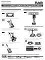
RAB WFRLA4R89FA120WS is a Gimbal Wafer FA that provides up to 25°vertical tilt and 355°horizontal rotation capability, making it suitable for various lighting applications. It features an aimable gimbal design and allows for color temperature adjustment, enhancing its versatility. The device comes with a driver box, template, and optional accessories, offering flexible installation options. Whether you're looking to illuminate a specific area or create ambient lighting, the RAB WFRLA4R89FA120WS can meet your lighting needs.
RAB WFRLA4R89FA120WS is a Gimbal Wafer FA that provides up to 25°vertical tilt and 355°horizontal rotation capability, making it suitable for various lighting applications. It features an aimable gimbal design and allows for color temperature adjustment, enhancing its versatility. The device comes with a driver box, template, and optional accessories, offering flexible installation options. Whether you're looking to illuminate a specific area or create ambient lighting, the RAB WFRLA4R89FA120WS can meet your lighting needs.


-
 1
1
-
 2
2


RAB WFRLA4R89FA120WS is a Gimbal Wafer FA that provides up to 25°vertical tilt and 355°horizontal rotation capability, making it suitable for various lighting applications. It features an aimable gimbal design and allows for color temperature adjustment, enhancing its versatility. The device comes with a driver box, template, and optional accessories, offering flexible installation options. Whether you're looking to illuminate a specific area or create ambient lighting, the RAB WFRLA4R89FA120WS can meet your lighting needs.
Ask a question and I''ll find the answer in the document
Finding information in a document is now easier with AI
Related papers
Other documents
-
RAB Lighting WFRL6R139FA120WS Operating instructions
-
-
-
-
-
-
-
-
-