Page is loading ...

Installation for
Model G56
Flow Reversal Valve
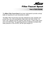
ASSEMBLY DIAGRAM
MOUNTING
• Pump must be located within 10 ft. (1.83 m) above or below
the keg or cask.
• Pump ports must be facing down to maximize pump
performance.
•Mounting grommets are part of pump assembly and add
stability.
• Fasten pump securely to wall or rack.
• If using a FOB device, mount it slightly above and directly
after the discharge of the pump. Caution: If a FOB is not
used, the pump will continue to cycle after the keg has run dry.
APPLICATION INFORMATION
Flojet’s G56 Flow Reversal Valve (FRV) is designed as an add-on
accessory for the G56 Beer Pump to allow beer line cleaners
to run cleaning solution through a Flojet G56 pump driven beer
system in both directions. Running cleaning solution through
draught beer systems in alternating directions from the faucet
to the tapping device (and vice versa) has been found
to enhance cleaning efficiency. Further, a multiple beer faucet
system utilizing G56 beer pumps with Flow Reversal Valves
allows for multiple lines to be cleaned at one time. This can
be done by connecting keg taps with double flushers
and connecting faucets with cleaning jumpers (see Line
Cleaning Diagram).
TYPICAL INSTALLATION
ASSEMBLY TO G56 PUMP
1. Slide port clips back against base of pump.
2. Insure that both O-rings of the FRV are adequately
lubricated.
3. Slide FRV ports into pump and secure with clips (see
Assembly Drawing).
4. Attach inlet tubing from keg to the left side port fitting and
secure with Oetiker Clamp (clamps not provided).
5. Attach discharge tubing to the right side port fitting and
secure with Oetiker Clamp.
6. Install air inlet and exhaust ports to pump.
TRIANGLES
MUST
LINE UP
4.84
(123)
4.92
(125)
1.59
(40)
2.96
(75)
1.11
(28)
9.13
(232)
2.20
(56)
8.63
(219)
4.52
(115)
DIMENSIONAL DRAWING
Inches (Millimeters) Consult factory if precise
Dimensional tolerances details are required.
± 0.06 inches
Model G56 Flow Reversal Valve
®
CO
2
Supply
Flow Reversal
Valve
Beer
Keg
Flojet G56
Beer Pump
FOB
Detector
Beer
Faucet
TECHNICAL SPECIFICATIONS
Materials of Construction (wetted parts): Polypropylene, EPDM
Temperature Limits:................................30°–120°F (-1.1°– 49°C)
Weight:..................................................................................3.3 oz.
Dimensions: ..............................5 3/16” H x 4 13/16” W x 2 3/8 D
Approvals: ......................................................................NSF listed

Motor
Driven
Pump
Line
Cleaning
Solution
Double
Flusher
Double
Flusher
Recirculating
Line Back To
Cleaning
Solution
Cleaning
Jumper
PRODUCT WARRANTY
Flojet warrants this product to be free of defects in material and/or workmanship for
a period of one year after purchase by the customer from Flojet.During this one year
warranty period, Flojet will at its option, at no charge to the customer, repair or
replace this product,if found defective, with a new or reconditioned product,but not
to include costs of removal or installation. No product will be accepted for return
without a return material authorization number. All return goods must be shipped
with transportation charges prepaid. This is only a summary of our Limited
Warranty. For a copy of our complete warranty, please request Form No.100-101.
RETURN PROCEDURE
Prior to returning any product to Flojet, call customer service for an authorization
number.This number must be written on the outside of the shipping package. Place
a note inside the package with an explanation for return as well as the authorization
number. Include your name,address and phone number.
PUMP/LINE CLEANING OPERATION
For operation of the pump, please see G56 Beer Pump
Installation Instructions (form #81000-303). For normal
dispensing, if a Flow Reversal Valve is added to the pump, the
set-up would be as shown in the Typical Installation Drawing.
Note that the valve is in the “Dispense Position” (see Valve
Positions Drawing).
For cleaning one line from the faucet to the keg tap:
1. Turn the valve to the “Reverse Flow” position.
2. Attach a cleaning jumper to the faucet.
3. Set FOB to bypass mode.
4. Pump the cleaning solution from the faucet to the keg tap.
5. Be sure to rinse system with cold, clean rinse water.
6. After cleaning and rinsing system, return all valves to
normal operating (Dispense) positions.
For cleaning multiple lines:
1. Attach a cleaning jumper to the first faucet.
2. Turn the valve to the “Reverse Flow” position.
3. Connect the keg tap from the first line to the keg tap of
the second line with a double flusher.
4. Leave the valve on the second pump in the "Dispense
Position.”
5. Connect the second faucet to the third faucet with a
cleaning jumper.
6. Repeat steps 2 through 5.
7. Set all FOBs to bypass mode.
8. Circulate cleaning solution through system.
9. Be sure to rinse system with cold, clean rinse water.
10.After cleaning and rinsing system, return all valves to
normal operating (Dispense) positions.
CAUTION: Do not close the system while running the
cleaning pumps. Excessive pressure build-up could
damage pumps.
LINE CLEANING DIAGRAM
© Copyright 2004, ITT Industries Printed in U.S.A. All Rights Reserved P/N 81000-382 02/04
UNITED KINGDOM
Flojet, Unit 1, Avant Business Centre
Denbigh West Industrial Estate
Milton Keynes, Bucks, England MK1 1DL
Tel: 44 1908 370088
Fax: 44 1908 373731
U.S.A.
Flojet
20 Icon
Foothill Ranch, CA 92610-3000
Tel: (949) 859-4945
Fax: (949) 859-1153
VALVE POSITIONS
TRIANGLES
MUST
LINE UP
Inlet From
Keg Tap
Outlet
To Keg Tap
Outlet To
FOB/Faucet
Inlet From
FOB/Faucet
TRIANGLES
MUST
LINE UP
Dispense
Position
Reverse Flow
Position
0
1.0
(3.8)
2.0
(7.6)
Flow Rate in GPM (l/min)
Pressure in PSI (Bar)
0.5
(1.9)
1.5
(5.7)
10
(0.7)
20
(1.4)
30
(2.1)
Air Inlet
Pressure
30 PSI Air Inlet
20 PSI Air Inlet
10 PSI Air Inlet
FLOW CURVE
HOSE CONNECTIONS
• All fittings are quick change.
• Secure with appropriate Oetiker Clamp for specified tubing
size or worm gear clamp 360 degree uniform clamping band.
•
It is advisable to secure all hoses to prevent excessive movement.
AVAILABLE PORT FITTINGS
•Standard Fitting:
3/8”–1/2” (10mm–13mm) Barb, plastic, elbow
•Optional Fittings:
• 1/4” (6.35 mm) Barb, stainless steel, straight
• 3/8” (9.52 mm) Barb, stainless steel, straight
•3/8” – 1/2” (10 mm – 13 mm) Barb, plastic, straight
•1/2” (13 mm) Barb, plastic, straight
•1/2” (13 mm) Barb, plastic, elbow
/