Page is loading ...

1
1383572-W2-A
These instructions must be left with the user
Mira Elite SE
9.8kW and 10.8kW Pumped Electric Shower
Installation and User Guide
For SPARES, ADVICE
or REPAIRS Please
call us on 01 531 9337
for (Eire only) or
0800 001 4040
(UK only)

21383572-W2-A
WARNING - This shower can deliver scalding temperatures, cause
re, electric shock or other personal injury if not operated, or
maintained in accordance with the instructions, warnings and
cautions contained in this guide and on the appliance.
Please read the important safety information and the operation section
of this guide before using the shower. Failure to follow the instructions
provided with this shower will invalidate the guarantee.
TO REDUCE THE RISK OF FIRE, ELECTRIC SHOCK OR INJURY:
1. This appliance can be used by all children and persons with reduced
physical, sensory or mental capabilities or lack of experience and
knowledge if they have been given supervision or instruction
concerning use of the appliance in a safe way and understand the
hazards involved.
2. Children shall not be allowed to play with the shower.
3. Cleaning and user maintenance shall not be made by children
without supervision.
4. Theoutletmustnotbeconnectedtoanytaporttingotherthan
thosespecied.
5. The showerhead must be descaled regularly. Any blockage of the
showerhead or hose can cause damage to the shower.
6. Warning! Do not switch on if there is a possibility that the water
in the heater is frozen.
7. The shower must be provided with means for local disconnection
from the supply mains having a contact separation in all poles
that provide full disconnection under overvoltage category III,
the instructions state that means for disconnection must be
incorporatedinthexedwiringinaccordancewiththewiringrules.
8. Installation of the shower must be carried out in accordance with
these instructions by qualied, competent personnel. Read all
instructions before installing the shower.
9. DO NOT switch the shower on if water starts leaking from the shower
case. Isolate the electrical supply to the shower immediately.
Important Safety Information

3
1383572-W2-A
10. DO NOT switch the shower on if the case appears to be damaged
or incorrectly tted. Isolate the electrical supply to the shower
immediately.
11. DO NOT increase the power setting or adjust the temperature
control rapidly while using the shower.
12. DO NOTswitchtheshoweroandbackonwhilestandinginthe
waterow.
13. Warning! DO NOT change the handset model. Fit only shower
headsrecommendedbyMiraanddonotanyadditionaldevice
torestrictthewateroutletow.
14. When adjusting the handset mode, point handset away from body
and make sure that the water temperature has stabilised before
continuing to shower.
15. Use caution when altering the water temperature, always check
the temperature before continuing to shower.
16.Switchtheshoweroattheelectricalisolatingswitchwhennotin
use. This is recommended with all electrical appliances.
17. Installation of the shower must be carried out in accordance with
these instructions by qualied, competent personnel. Read all
instructions before installing the shower.
18. Isolate the electrical and water supplies before commencing
installation. The electricity must be isolated at the consumer unit
and the appropriate circuit fuse removed, if applicable. Mains
connections are exposed when the cover is removed.
19. DO NOT install the shower in areas with high humidity and
temperature (i.e. Steam rooms and saunas).
20. DO NOT install the shower where it may be exposed to freezing
conditions. Ensure that any pipework that could become frozen is
properly insulated.
21. Warning! DO NOT connect the outlet of the shower to any tap,
control valve, trigger operated handset or showerhead other than
thosespeciedforusewiththisshowerastheoutletactsasavent
for the tank body. Only Kohler Mira recommended accessories
should be used.

41383572-W2-A
22. DO NOTperformanyunspeciedmodications,ordrillorcutholes
in the product other than instructed by this guide. When servicing
only use genuine Kohler Mira replacement parts.
23. Always check the water temperature is safe before entering the
shower.
24. The water supplies to this product must be isolated if the product is
not to be used for a long period of time. If the product or pipework
is at risk of freezing during this period they should also be drained
of water.
25. If the shower is dismantled during installation or servicing then,
upon completion, an inspection must be made to ensure all
electrical connections are tight and that there are no leaks.
26. DO NOT t the shower to a mains water supply or where the
maximumspeciedpressuremayexceed.
27. Maximum Static Pressure is 100 kPa (1 bar).
Decommissioning and Recycling
When this appliance has reached the end of its serviceable life, it
should be disposed of in a safe manner, in accordance with current
local authority recycling, or waste disposal policy. For more information
aboutrecycling,pleasecontactyourlocalcounciloce.

5
1383572-W2-A
Pack Contents
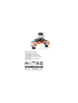
1 x Pumped Electric Shower
Pumped Electric Shower
3 x Screws
1 x Compression Nut
1 x Olive
3 x Wall Plugs

61383572-W2-A
Shower Fitting
2 x Slide Bar Support
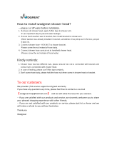
1 x Showerhead
Multimode
1 x Shower Hose
2 x Hose Seal
2 x Mounting Pack
1 x Clamp Bracket
1xRetainingRing
1 x Slide Bar
2 x Cap

7
1383572-W2-A
DesignRegistration: 003617653-0006
Patents: GB 2 289 323, 2 341 667, 2 359 339, 2 427 460, 2 432 201
Ireland:80655,82835,83692
Thank you for choosing a Mira shower. To enjoy the full potential of your new shower,
please take time to read this guide thoroughly, and keep it handy for future reference.
Products manufactured by Kohler Mira Ltd are designed to be safe, provided that
they are installed, used and maintained in good working order, in accordance with
our instructions and recommendations.
Follow all warnings, cautions and instructions contained in this guide, and on, or
inside the shower. This guide is also available in digital format from our website or
by contacting customer services.
Domestic
Light Commercial
Heavy Commercial
Healthcare
Product Variant Model No. Colour
Mira Elite SE 9.8 kW J11A
White
Chrome
Mira Elite SE Dual 9.8 kW J11Ad
White
Chrome
Mira Elite SE 10.8 kW J11B
White
Chrome
Introduction
Products Covered
Recommended Usage
Patents and Design Registration

81383572-W2-A
Specications
Dimensions
Height 363 mm
Width 270 mm
Depth 82 mm (110 mm including Dials)
Plumbing
Variant
9.8 kW and 10.8 kW
Maximum Static Pressure 100 kPa (1.0 bar)
Minimum Static Pressure 0.8 kPa (0.008 bar)
Maximum Inlet Temperature 30°C
Minimum Inlet Temperature 2°C
Inlet Connection 15 mm Compression
Maximum Water Hardness 200ppmCaCOɜ*
Outlet Connection 1/2”BSPMaletoexiblehose
Electrical
Variant
9.8 kW 10.8 kW
Nominal Power at 240 V ac 9.8 kW 10.8 kW
Nominal Power at 230 V ac 9 kW 9.9 kW
RecommendedMCBRating 40 A 45 A
Maximum Supply Cable Size 16 mm²
RecommendedRCDRating 30 mA tripping current
RecommendedIsolatorSwitch 45 A double-pole with 3 mm contact
separation
ApplianceSealingRating IP X4 - suitable for installation in Zone 1
Maximum Ambient Temperature 30°C
Minimum Ambient Temperature 2°C
*Watersupplieswithawaterhardnessabove200ppmCaCO3shouldbettedwith
a water softener or other scale reducing device.

9
1383572-W2-A
Indicative annual electricity consumption (kWh), based upon 2100 Wh daily water
energy demand. Actual electricity consumption will depend on kW rating and the
duration and frequency of use.
Product Information
ThisrangeofelectricshowerscomplieswiththefollowingEuropeandirectives:
2014/35/EU Low Voltage Directive, 2014/30/EU EMC Directive,2011/65/EURoHS
Directive
This range of electric showers are high power appliances and are subject to
conditional connection. If the main electrical supply fuse is rated less than 80 Amps,
thelocalelectricitysupplycompanymustbecontactedtoconrmiftheelectrical
supply is adequate.
This range of showers complies with the requirements of the UK’s water regulations.
European Conformity Information
Eco-Design/Energy Labelling
Mira Elite SE
9.8 kW 10.8 kW
LoadProle XS XS
EciencyClass A A
Eciency(%) 39.0 38.9
Daily Electricity Consumption (kWh) 2.172 2.177
Annual Electricity Consumption (kWh) 473 474
For domestic installations, Mira Showers guarantee the Mira product
against any defect in materials or workmanship for a period of two
yearsfromthedateofpurchase(showerttingsforoneyear).
For non-domestic installations, Mira Showers guarantee the Mira
product against any defect in materials or workmanship for a period of
one year from the date of purchase. For Terms and Conditions refer
to the back cover of this guide.
Guarantee

101383572-W2-A
1. The plumbing installation must comply with all national or local water regulations
and all relevant building regulations, or any particular regulation or practice
speciedbythelocalwatersupplycompany.
2. The shower is designed to operate with a gravity fed water supply providing
apressurefrom0.8kPa*(0.008bar/80millimetreshead)to100kPa(1bar
/ 10 metres head, the vertical distance from the base of the cold water cistern
to the top of the shower unit). The shower must have its own separate supply
from the cistern.
DO NOT FIT THE SHOWER TO A MAINS WATER SUPPLY OR WHERE THE
MAXIMUM SPECIFIED PRESSURE MAY BE EXCEEDED!
Failure to comply with these restrictions may result in product damage not
covered by the guarantee.
*Note: In practice the minimum head required will increase with pipe length.
See “Pipework” for further guidance which includes a calculation table to make
sure that adequate head is available for any given installation.
Plumbing
Installation Requirements
Incorrect Cistern Take Off
Debris from the bottom of the
cistern and air generated when
thecisternrellswillenterthe
shower supply.
Correct Cistern Take Off
Positioned away from the ball
valve, with a 25 mm distance
from the base of the cistern.
This connection will prevent
air and debris entering the
shower supply.
To shower
unit only.
25 mm
25 Gallon/113 Ltr Cistern

11
1383572-W2-A
Hose retaining ring tted and shower ttings xed at a suitable height
preventing dirty water backow
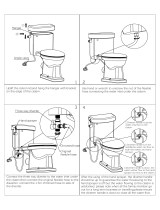
3. DO NOT install the product in a position or location
that will limit access for servicing.
4. A suitable position for the shower will have a minimum
clear distance of 200 mm above and below the
showerunittoallowforcoverremovalandretting.
5. Thepositionoftheshowerandshowerttingsmust
provide a minimum air gap of 25 mm between the
showerhead and the spill over level of any bath,
shower tray or basin. There must be a minimum
distance of 30 mm between the showerhead and the
spill over lever of any toilet, bidet or other appliance
withaFluidCategory5backowrisk.
Note: There will be occasions when the hose retaining ring will not provide
a suitable solution for Fluid Category 3 installations, in these instances
an outlet double check valve must be tted, this will increase the required
supply pressure typically by 10kPa (0.1 bar). Double check valves tted in
the inlet supply to the appliance cause a pressure build up, which aect
the maximum static inlet pressure for the appliance and must not be tted.
For Fluid category 5 double check valves are not suitable.
Zone of
BackflowRisk
30 mm
Minimum
Toilet or Bidet
FC5
Hand Basin
FC3
Bath or Shower
Tray FC3
Electric
Shower
25 mm
Minimum
25 mm Minimum
200 mm
200 mm

121383572-W2-A
6. The shower is suitable for installation within the shower area. The shower is
ttedwithaninternalpressurereliefvalveandmustbeinstalledoverawater
catchment area.
7. Position the shower where the controls are at a convenient height for the user.
Position the showerhead so that the water sprays in line with the bath or across
the opening of a shower cubicle. The showerhead must not spray directly onto
the shower unit during normal use. The installation must not cause the shower
hose to be kinked during normal use.
8 Theshowermust be tted to a waterproof, at and even wall surface. The
3 screws (No. 8 x 1¼”) and wall plugs supplied are suitable for most solid wall
installations.Alternativexingscrewsforpanelstructuresarenotsupplied.Useall
3xingpointstosecuretheshowerunit,besuretousexingsappropriatefor
the chosen wall structure and environment.
DO NOTttheshowertothewallandtileuptothecaseorsealthegapbetween
the shower and the wall surface with sealant.
9 The shower is intended to be permanently connected to a gravity fed water
supply using the inlet connection supplied as part of the shower unit.
DO NOTuseanyothertypeoftting.
10. Use a minimum of 15 mm diameter supply pipework. For long pipe runs, this
should be increased to 22 mm (see “Pipework” for guidance and calculation
table).Whenusingexibleplasticpipeitisessentialthatthepipeiskeptatto
minimise air build up in the system.
11. Afullbore/nonrestrictiveservicingvalvemustbettedinareadilyaccessible
position adjacent to the shower to facilitate maintenance of the shower.
DO NOT use a valve with a loose washer plate (jumper) as this can lead to a
build up of static pressure.
12. The shower is not designed to be plumbed directly from the rear. For rear-entry
supply, add an elbow to the supply pipe and connect as a rising or falling supply.
We recommend a falling supply to prevent air lock in the pipework.
13. If pipework and/or electrical cables enter the shower from the rear through a
hole in the wall, provision must be made to prevent water ingress back into the
wall structure.
14. DO NOT apply excessive force to plumbing connections; always provide
mechanical support when making plumbing connections. Any soldered joints
should be made before connecting the shower.
15. A water treatment device should be installed where the water hardness may
exceed 200 ppm. Malfunctions caused by excessive limescale formation are
not covered by the guarantee.
16. DO NOT perform the electrical installation until the plumbing has been completed
and checked for leaks.
17. The water supplies to this product should be isolated if the product is not to be
used for a long period of time. If the product or pipework is at risk of freezing
during this period they should also be drained of water.

13
1383572-W2-A
Size Quantity
Head Loss
(mm)
15 mm Pipe 270
22 mm Pipe
15 mm Elbow 55
22 mm Elbow
Minimum Eective Head 80
(X) mm 405
Longpiperunsandexcessiveuseof90°elbowttingswillsignicantlyreducethe
available head to supply the shower unit. The pipework table provided should be
used to ensure that an adequate pressure is available for any given application.
Pipework
Pipework Schematic Diagram
A
B
X
Usethefollowingtabletocalculatethedimension(x)togiveaminimumeectiveheadof
80 mm required to produce a satisfactory shower in all conditions.
The example below is based on the “Pipework Schematic Diagram” with 15 mm pipework,
A = 1.5 m, B = 0.75 m.
(A) 1.5 + (B) 0.75 = 2.25 x 120
(A) + (B) = x 20
Number of Elbows 1 x 55
Number of Elbows x 15

141383572-W2-A
Electrical
1. The electrical installation must comply with BS 7671 (commonly referred to as
theIEEWiringRegulations)andallrelevantbuildingregulations,oranyparticular
regulationorpracticespeciedbythelocalelectricitysupplycompany.
2. Ensure that all circuit protection devices, switches and cabling are adequate
for the rated current of the shower and that the rating of the electricity supply
company fuse and the consumer unit are adequate for the additional demand.
3. The shower must be earthed. Ensure that any supplementary bonding complies
with the relevant regulations.
4. Theshowerisintendedtobepermanentlyconnectedtothexedelectricalwiring
of the mains system. A separate supply must be provided from the consumer
unit to the shower.
5. The shower must be provided with means for local disconnection that is
incorporatedintothexedwiringinaccordancewiththerelevantlocalwiring
regulations. This must be a double pole switch, which has at least 3 mm contact
separation in each pole. The switch can be a pull-cord type mounted to the
ceiling within the shower room or a rocker type switch mounted to the wall in
the applicable zone area.
6. For new installations a 30 mA Residual Current Device (RCD) must be
incorporated into the electrical supply to the shower in accordance with the
current wiring regulations. When replacing an existing electric shower we
recommendthata30mARCDisincorporatedinaccordancewithcurrentwiring
regulations if not already provided.
7. Check all electrical connections are tight, to prevent overheating, before
switching on the electrical supply.
DO NOT apply excessive force to the terminal block.
8. DO NOT supply any other electrical equipment including extractor fans or pumps
via the shower unit.
9. DO NOT switch on the electrical supply until the plumbing has been completed
and checked for leaks.
Electrical Schematic Diagram
Consumer Unit
Double Pole
Isolating Switch
Shower
Unit

15
1383572-W2-A
Shower Unit Wiring Diagram
THERMALSWITCH
LATCHING
SWITCH
MOTOR
M
INLET
CONNECTOR
PUMPMOTOR
PUMPPOWERSUPPLY
RED
BLACK
GREENR
BLUE
BLUE S
BLUE S
BLUE K
BLUE Q
BROWNA
GREENB
BLUE C
BLUE C
TERMINALBLOCK
ASSEMBLY
HEATERTANK
ASSEMBLY
MICROSWITCHES
REDF
REDF
REDE
BROWNG
BROWNG
BROWNH
BROWNH
LED
BROWNP
BROWNP
BROWNA
BROWND
BROWND
BLUE Q
L E
N
INLETCONNECTOR
ASSEMBLY
SOLENOID
BLUE K
GREYJ
GREYT
GREYT
GREYT
LATCHING
SWITCH
BROWND
POWERLED
USERSELECTEDFLOW/
POWERSWITCH
TANK
P
HH
P
SOLENOID
VALVE
N
L
E

161383572-W2-A
Warning! Isolate the electrical and water supplies before installing the shower.
Decideonasuitablepositionfortheshowerunitandttings.
See “Installation - Plumbing”andseperatettingsguideifttingdualproduct.
Cover
Service
Tunnel
Outlet
Bung
Bung
Screws
Screws
Note: Ensure that there are sucient
lengths of supply pipe and electrical
cable to reach the connection points.
Caution! DO NOT drill into cables or
pipes in the wall.
Removethefourscrewsthatholdsthecover
on and remove the cover.
Removethebungs.
Use the installation template provided, level
and mark the positions of the three xing
holes.
Drillthreeholestosuitthexingscrewsand
wall plugs.
Install the Shower

17
1383572-W2-A
Note: DO NOT extend beyond thinned
section.
Note: Thoroughly ush the supply pipe
before connecting to the product.
Determine the direction and route of the
electric supply cable.
Determine the direction and route of the
incoming water supply: falling (entering the
shower from the top), or rising (entering the
shower from the bottom).
Note: Top entry water inlets are preferable
to reduce the risk of pipework airlocks.
The rear case has thinned sections that
can be removed to allow entry of the
supply pipe and electrical cables.
Removethetopthinnedsectionoftherear
case for a falling supply, or remove the
bottom thinned section at service tunnel
for a rising supply.
Thinned
Section
RearCase

181383572-W2-A
Rotate the inlet connector to suit the
direction of the incoming water supply.
Fix the shower unit to the wall, 3 x No. 8 x
1¼” screws and wall plugs are supplied.
See “Installation - Plumbing” for further
details.

19
1383572-W2-A
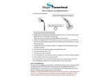
Check the inlet filter is in position before
connecting inlet supply.
Connect the inlet supply pipe to the inlet
connector using the compression nut and olive
(supplied). DO NOT use jointing pastes to make
water connection.
Support the inlet connector as shown when
tighteningcompressiontting.
Upon completion of the installation ensure
connections and back case are not under any
stress due to misaligned pipework or electrical
cables.
Note: DO NOT exert strain on the
terminal block. Make sure that the
electrical connections are tightly
screwed down.
Turn on the water supply and check for leaks.
Stripbacksucientoutercableinsulation
to enable routing to terminal block.
Fit an earth sleeve to the earth wire (not
supplied).
Loosen the screws in the terminal block
and insert the wires.
Tighten the screws in the terminal block,
ensure the wires are secure and tight.
N (Neutral) = Blue Wire
L (Live) = Brown Wire
(Protective Earth) =
Green Sleeved Wire

201383572-W2-A
Ensure the earth bonding complies with
relevant regulations.
Fit the service tunnel.
Ensure the control dials are aligned with
the spindles and replace the cover.
Tighten the four cover screws (DO NOT
use electric screwdrivers to tighten the
screws).
DO NOT use alternative screws to
secure the cover. This can cause
internal damage to the appliance.
DO NOT seal around any part of
appliance.
This completes the installation,
follow the guidelines in section
‘COMMISSIONING’ to prepare the
shower for use.
/