
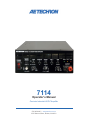
7114
Operator’s Manual
Precision Industrial AC/DC Amplier
574.295.9495 | www.aetechron.com
2507 Warren Street, Elkhart, IN 46516

Limited One-Year Warranty
we will give you an authorization to return the product
for service. All components must be shipped in a factory
pack or equivalent which, if needed, may be obtained
from us for a nominal charge. We will take corrective ac-
tions within a reasonable time of the date of receipt of
the defective product. If the repairs made by us are not
satisfactory, notify us immediately.
DISCLAIMER OF CONSEQUENTIAL AND
INCIDENTAL DAMAGES
You are not entitled to recover from us any consequen-
tial or incidental damages resulting from any defect in
our product. This includes any damage to another prod-
uct or products resulting from such a defect.
WARRANTY ALTERATIONS
No person has the authority to enlarge, amend, or
modify this warranty. The warranty is not extended by
the length of time for which you are deprived of the use
of this product. Repairs and replacement parts provided
under the terms of this warranty shall carry only the
unexpired portion of this warranty.
DESIGN CHANGES
We reserve the right to change the design of any
product from time to time without notice and with no
obligation to make corresponding changes in products
previously manufactured.
LEGAL REMEDIES OF PURCHASER
There is no warranty that extends beyond the terms
hereof. This written warranty is given in lieu of any oral
or implied warranties not contained herein. We disclaim
all implied warranties, including, without limitation, any
warranties of merchantability or tness for a particular
purpose. No action to enforce this Warranty shall be
commenced later than ninety (90) days after expiration
of the warranty period.
AE Techron, Inc.
Customer Service Department
2507 Warren Street
Elkhart, IN 46516
U.S.A.
574.295.9495
www.aetechron.com
SUMMARY OF WARRANTY
AE TECHRON INC. of Elkhart, Indiana (Warrantor) war-
rants to you, the ORIGINAL COMMERCIAL PURCHASER
ONLY of each NEW AE TECHRON INC. product, for a
period of one (1) year from the date of purchase, by the
original purchaser (warranty period) that the product
is free of defects in materials or workmanship and will
meet or exceed all advertised specications for such a
product. This warranty does not extend to any subse-
quent purchaser or user, and automatically terminates
upon your sale or other disposition of our product.
ITEMS EXCLUDED FROM WARRANTY
We are not responsible for product failure caused by
misuse, accident or neglect. This warranty does not
extend to any product on which the serial number has
been defaced, altered, or removed. It does not cover
damage to loads or any other products or accessories
resulting from AE TECHRON INC. product failure. It does
not cover defects or damage caused by the use of unau-
thorized modications, accessories, parts, or service.
WHAT WE WILL DO
We will remedy, at our sole discretion, any defect in
materials or workmanship by repair, replacement, or
refund. If a refund is elected, you must make the defec-
tive or malfunctioning component available to us free
and clear of all liens or other encumbrances. The refund
will be equal to the actual purchase price, not includ-
ing interest, insurance, closing costs, and other nance
charges less a reasonable depreciation on the product
from the date of original purchase. Warranty work can
only be performed at our authorized service centers or
at our factory. Expenses in remedying the defect will be
borne by AE TECHRON INC., including one-way surface
freight shipping costs within the United States. (Pur-
chaser must bear the expense of shipping the product
between any foreign country and the port of entry in the
United States and all taxes, duties, and other customs
fees for such foreign shipments.)
HOW TO OBTAIN WARRANTY SERVICE
When you notify us of your need for warranty service,

Contents
1 Introduction ....................................................................................................................................5
2 Amplier Unpacking and Installation ..............................................................................................6
2.1 Safety First ............................................................................................................................6
2.2 Unpacking .............................................................................................................................6
2.3 Installation .............................................................................................................................6
3 Connections and Startup ...............................................................................................................7
3.1 Controlled Current Operation ................................................................................................7
3.2 Connecting the Load .............................................................................................................7
3.3 Connecting the Input Signal ..................................................................................................7
3.4 Connecting the AC Supply ....................................................................................................8
3.5 Start-up Procedures ..............................................................................................................8
4 Operation .....................................................................................................................................9
4.1 Front-Panel Controls .............................................................................................................9
4.2 Front-Panel Indicators .........................................................................................................10
4.3 Connectors .......................................................................................................................... 11
5 Advanced Conguration ............................................................................................................... 13
5.1 Internal Jumpers and Settings.............................................................................................13
6 Applications ..................................................................................................................................16
6.1 RAIL V Settings for Increased Voltage or Current ............................................................... 16
6.2 Remote Status and Control using the DB-9 Connector.......................................................16
6.3 Controlled Current Operation ..............................................................................................18
6.4 Using the 7114 as a Battery Simulator/Four-Quadrant Supply ...........................................22
6.5 Using the 7114 for Overvoltage Testing ..............................................................................22
6.6 Using the 7114 for PSRR Measurements ...........................................................................23
6.7 Using the 7114 for Ampler CMRR Measurements .............................................................26
6.8 Using the 7114 to Create Complex Waveforms ..................................................................27
7 Maintenance ................................................................................................................................28
7.1 Clean Filter and Grills .......................................................................................................... 28
8 Troubleshooting ...........................................................................................................................29
8.1 Introduction & Precautions ..................................................................................................29
8.2 Visual Inspection .................................................................................................................29
8.3 No Signal .............................................................................................................................29
8.4 No Power/Power Switch Not Illuminated ............................................................................. 29
8.5 Fault LED is Illuminated ......................................................................................................30
8.6 Factory Service ...................................................................................................................31
9 Specications ...............................................................................................................................32


97-8004339_05-08-18
Information subject to change
5
7114 OPERATOR’S MANUAL – SECTION 1
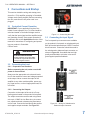
1 Introduction
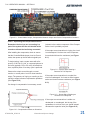
Congratulations on your purchase of a 7114
precision industrial AC/DC amplier. AE Techron’s
7114 amplier is a 400-VA, 4-quadrant, AC and
DC amplier that provides exceptional versatil-
ity and value. Compact size, user congurability,
DC-Max™ topology, and AE Techron toughness
makes the 7114 the ideal lab partner for automo-
tive conducted immunity testing, PSRR testing, or
any application where more voltage or current is
needed than is available from the signal source.
Compact Power
The 7114 weighs just 20 pounds and ts into one-
half of a 2U rack space, but still can output up to
400 watts RMS continuous. This makes the 7114 a
great choice when size or portability are important
selection criteria.
Versatile
Front panel user controls give the 7114 a wide
range of possible uses; gain, maximum current,
and DC oset can be xed or innetely varied. The
choice of AC or DC coupling makes it suitable both
for DC applications and for driving objects like cou-
pling transformers or piezo elements that shouldn’t
see DC. All controls can be turned o when only
a durable, high-current amplier or DC source
is needed. Or each function can be individually
enabled to provide the unique set of capabilities
needed at the moment.
The 7114 can supply a xed DC voltage indenite-
ly, making it essential for DC power tests lasting
minutes or hours.
It can also produce a DC output without an input
signal and independent of amplier gain. When an
inexpensive function generator is added, the 7114
becomes a versatile test solution providing DC
with both ripple and dropout.
DC-Max™
7114 is built with our new DC-Max topology. Ampli-
ers with DC-Max have long term DC power that
is more than 40% greater than traditional designs.
This increased DC performance better matches
the power requirements found in DC conducted
immunity and PSRR testing.
AE Techron Toughness
The 7114 is compact in size, but it is designed
using the same conservative design rules and
protection systems that have made AE Techron
ampliers the toughest audio bandwidth ampliers
available.
Figure 1.1 – 7114 Front and Back Panels
Features
• 15A DC and capable of reproducing
500 kHz ripple or < 4μs dropout/pulses.
• User-variable DC offset: ±20V or ±45V.
• User-adjustable current limit: 25A to 1A.
• Compact 1/2-rack width, 2U height;
weighs only 20 lbs.
• Four-quadrant operation.
• AC/DC coupled.
• AE Techron Tough: Protection from over-
temperature, over-current, over/under
supply voltages; will drive capacitive
and inductive loads.

Information subject to change
97-8004339_05-08-18
7114 OPERATOR’S MANUAL – SECTION 2
6
2 Amplier Unpacking and
Installation
The 7114 amplier is a precision instrument that
can be dangerous if not handled properly. Lethal
voltages are present in both the AC input supply
and the output of the amplier. For this reason,
safety should be your primary concern when you
setup and operate this product.
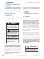
2.1 Safety First
Throughout this manual special emphasis is
placed on good safety practices. The following
graphics are used to highlight certain topics that
require extra precaution.
Along with any additional accessories purchased
by the customer, all 7114 models ship with the fol-
lowing:
• 7114 Amplifier
• Power Cord
• 7114 Operator’s Manual (on USB drive) and
7114 Quick Start sheet
2.3 Installation
The 7114 amplier is packaged in a rugged pow-
der-coated steel chassis. This chassis is 2U (rack
units) tall and has a width one-half of a standard
EIA (Electronic Industries Association) rack. It
can be rack mounted using a custom rack shelf/
adapter (not supplied). This adapter can be used
to mount one unit (with an adjacent opening for
storage) or two units side-by-side in a single 2U
height rack space. Use standard rack mounting
hardware to mount the unit. Use nylon washers if
you wish to protect the powder-coat nish on the
front of the product.
Optionally, the unit can be placed on a bench top;
please keep in mind that the protective powder-
coating can be scratched when other equipment is
placed on it, especially when there is dirt present.
Allow ample space on the sides and especially the
back of the amplier for heated air to escape. The
unit should be mounted in a rack that is adequately
ventilated and not sealed. Likewise, the front of
the unit should be unobstructed to allow cool air to
enter the amplier.
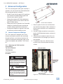
DANGER represents the most severe
hazard alert. Extreme bodily harm or
death will occur if these guidelines are
not followed. Note the explanation of the
hazard and instruction for avoiding it.
DANGER
WARNING alerts you to hazards that
could result in severe injury or death.
Note the explanation of the hazard and
the instructions for avoiding it.
WARNING
CAUTION indicates hazards that could
result in potential injury or equipment
or property damage. Once again, note
the explanation of the hazard and the
instructions for avoiding it.
CAUTION
Do not operate the amplier in a small
sealed chamber of any kind. Improper
operations and overheating will result.
CAUTION
2.2 Unpacking
All units are tested and inspected for damage
before leaving the factory. Carefully unpack and
inspect the amplier for damage. Please note
any damage for future reference and notify the
shipping company immediately if damage is
found. Also, please save the shipping carton and
materials as evidence of damage and/or for return-
ing the unit for repair.

97-8004339_05-08-18
Information subject to change
7
7114 OPERATOR’S MANUAL – SECTION 3
3 Connections and Startup
This section details the wiring and startup proce-
dures for a 7114 amplier operating in Controlled-
Voltage mode (factory default). Before connecting
the unit, make sure the AC power cord is un-
plugged.
3.1 Controlled Current Operation
IMPORTANT: If your application requires Con-
trolled Current operation, the 7114 rst should be
wired and tested in Controlled-Voltage mode to
verify that the input signal and the amplied output
are operating correctly. Once proper operation is
conrmed, refer to the Applications section of this
manual for instructions on conguring and operat-
ing your product in Controlled-
Current mode.
3.2 Connecting the Load
3.2.1 Preparation and Cautions
Before connecting the unit, make sure the AC
power is disconnected.
Always use the appropriate wire size and insula-
tion for the maximum current and voltage expected
at the output. Never connect the output of the
amplier to any other model amplier, power sup-
ply, signal source, or other inappropriate load; re
can result.
3.2.2 Connecting the Outputs
Connection to the output of the unit is to 5-way
binding posts located on the product’s front panel.
The output connection can be made using tinned
wire up to 12 AWG in size. Bare wire, pin connec-
tors, spade terminals or banana plug terminators
can be used. Connect the load across the positive
and negative output terminals. See Figure 3.1.
3.3 Connecting the Input Signal
Two front-panel input connectors are available
on the product’s front panel: an unbalanced Input
BNC jack and a balanced Input “WECO” terminal
block connector. Connection should be made to
the unbalanced or balanced input connector as
shown in Figure 3.2. Use cables that are high
quality and shielded to minimize noise and to
guard against possible feedback.
ELECTRIC SHOCK HAZARD.
Output potentials can be lethal. Make
connections only with AC Power OFF
and input signals removed.
WARNING
Figure 3.1 – Connecting the Load
Figure 3.2 – Wiring for Unbalanced or
Balanced Input Connector

Information subject to change
97-8004339_05-08-18
7114 OPERATOR’S MANUAL – SECTION 3
8
The product also can receive input signal through
the back-panel DB-9 connector. In addition to
signal input, this connector can be used for remote
control and monitoring applications. Please refer to
the Applications section of this manual for infor-
mation on using the DB-9 connector.
The 7114 can receive input signal simultaneously
from all three input connectors, allowing for the
creation of complex input waveforms from up to
three separate input devices. Please refer to the
Applications section of this manual for informa-
tion on complex waveform creation.
3.4 Connecting the AC Supply
The power cord connects to a standard 15A 3-pin
IEC-type male connector on the back panel (see
Figure 3.3). Make sure the power switch on the
front panel is switched to the OFF (O) position.
Make sure the power cord is inserted and seated
fully into the IEC connector by moving it slightly
back and forth and up and down while pushing
in. The power cord is relatively sti and should be
routed so that there is no excessive force pulling to
the sides or up or down that would stress the pins
or internal connections.
Figure 3.3 – Closeup of AC Mains Outlet
3.5 Start-up Procedures
1. If an input signal source is required, con-
nect the signal source and turn down the
input signal level.
2. If a DC supply is required, push the Oset
switch to enable the Variable oset, then
use the Oset variable control knob to
select the desired DC supply.
3. Depress the POWER switch to turn the
unit ON.
4. Turn up the level of your signal source until
the green SIGNAL LED is lit (>300 mV).
5. Turn up the variable Gain control on the
amplier (if enabled) until the desired volt-
age or power level is achieved.
6. Adjust the input signal level to achieve the
desired output level.

97-8004339_05-08-18
Information subject to change
9
7114 OPERATOR’S MANUAL – SECTION 4
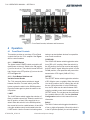
4 Operation
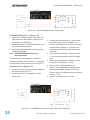
4.1 Front-Panel Controls
This section provides an overview of Front-Panel
controls found on the 7114 amplier. See Figure
4.1 for control locations.
4.1.1 POWER Switch
The lighted rocker POWER switch controls the AC
mains power to the unit. Switch to the ON position
(|) to turn the unit on. The switch’s internal LED will
light. Switch to the OFF position (O) to turn the unit
o. See Figure 4.1.
4.1.2 Push Button Switches and
Variable Control Knobs
The 7114 uses push button switches to toggle
between functions. For each switch, press the
button to place the switch in the DOWN position.
Press the button again to place the switch in the
UP position.
I LIMIT
The I LIMIT button-switch toggles the selection of
xed or variable current limit. When the switch is in
the UP position, a xed, 25A current limit is en-
abled. When the switch is in the DOWN position,
the current limit can be varied between 1A and 25A
using the variable control knob located below the
I LIMIT switch. Use the Current Limit setting when
testing to protect delicate devices from possible
over-current conditions.
COUPLING
The COUPLING button-switch toggles the selec-
tion of DC or AC coupling. When the switch is in
the UP position, the unit can receive and amplify
both DC and AC signal. When the switch is in the
DOWN position, a low-pass lter will prevent the
transmission of DC signal (-3dB at 5.5 Hz).
OFFSET
The OFFSET button-switch toggles the selection
of DC oset to none or variable. When the switch
is in the UP position, the DC oset of the unit will
be zero. When the switch is in the DOWN posi-
tion, the DC oset can be varied between ±20V
using the variable control knob located below the
OFFSET switch. The unit also can be congured
for a variable oset of ±45V. See the Advanced
Conguration section in this manual for more
information.
RAIL V
The RAIL V button-switch toggles the selection
of low- or high-rail operation. When this switch is
in the UP position (default), the unit will operate
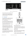
Figure 4.1 – Front Panel Controls, Indicators and Connectors

Information subject to change
97-8004339_05-08-18
7114 OPERATOR’S MANUAL – SECTION 4
10
with the power supply rails in a series congura-
tion for high-voltage output. When this switch is in
the DOWN position, the unit will operate with the
power supply rails in a parallel conguration for
high-current output. This will result in a maximum
voltage potential of 90V (high-rail) or 45V (low-
rail). For more information on how to set the RAIL
V switch for increased voltage or current, see the
Applications section.
NOTE: If the RAIL V switch setting is changed
from high to low rails while the unit is operating,
the output signal may clip.
GAIN
The GAIN button-switch toggles the selection of
xed or variable gain. When the switch is in the UP
position, a xed gain of 10X is enabled. When the
switch is in the DOWN position, the gain can be
varied between 0-10X using the variable control
knob located below the GAIN switch.
4.2 Front-Panel Indicators
Three status indicators are located on the front
panel. See Figure 4.1 for component locations.
4.2.1 SIGNAL Indicator
The SIGNAL LED indicates the unit is powered
and receiving an input signal above 300 mV.
4.2.2 OVLD Indicator
The OVLD LED indicates that the output of the unit
could not follow the input signal due to voltage or
current limits.
To correct the overload condition, turn down the
level of the input signal and/or the gain control on
the front panel until the OVLD LED turns o.
4.2.3 FAULT Indicator
The FAULT indicator will light when any one of four
conditions occurs:
Over-temperature Condition
The FAULT indicator may light when the unit’s
thermal switches and/or transformers have over-
heated.
When an over-temperature condition occurs, the
unit’s fans will continuously operate at high speed
until the over-temperature condition is resolved.
Turn down your input signal and allow the fans
to operate at high speed until they automatically
switch to low-speed operation, indicating the unit
has cooled enough to resume operation. Then
cycle the power switch to return the unit to normal
operation. If the unit does not return to normal
operation, it may require servicing. Please see the
Troubleshooting section for more information.
NOTE: If the unit’s transformers have overheated,
the fans will typically need to operate at high
speed for at least 10-15 minutes in order to resolve
the over-temperature condition.
Over-voltage Condition
The FAULT indicator may light when the AC mains
voltage is more than +10% of nominal.
To clear an over-voltage fault condition, the AC
mains must be brought down to the nominal value.
Once the over-voltage condition has been cleared,
cycle the power switch to return the unit to normal
operation. If it does not return to normal opera-
tion, the unit may require servicing. Please see the
Troubleshooting section for more information.
Overload Condition
If the unit’s internal Overload Latch jumper setting
has been changed from the factory default and
congured for unit shut down when an overload
condition occurs, the FAULT indicator will light
when an overload condition occurs.
To clear the fault-at-overload condition, turn down
your input signal, and then cycle the unit’s power
switch to return it to normal operation.
Please refer to the Advanced Conguration sec-
tion for more information on the Overload Latch
jumper and fault-at-overload setting.
Component Failure
The FAULT indicator may light when an output
transistor or other component has failed.

97-8004339_05-08-18
Information subject to change
11
7114 OPERATOR’S MANUAL – SECTION 4
If the unit does not return to normal operation after
correcting or ruling out over-temperature, over-
voltage and overload conditions, it may require
servicing. Please see the Troubleshooting sec-
tion for more information.
4.3 Connectors
This section provides an overview of the connec-
tors found on the 7114 amplier. Please refer to
Figures 4.1 and 4.2 for visual locations.
4.3.1 Input Connectors
The 7114 provides two front-panel and one back-
panel connector for signal input. The front-panel
BNC connector provides unbalanced input, while
the front-panel WECO and the back-panel DB-9
connectors provide balanced input.
Signal input can occur from one, two, or all three
connectors simultaneously. In addition, a DC
oset signal can be added, allowing for the con-
trol and amplication of a wide range of complex
waveforms. See the Applications section of this
manual for more information.
Unbalanced BNC Connector
The unbalanced BNC connector is located on the
unit’s front panel to the right of the Power switch.
It provides standard unbalanced signal input. See
Figure 4.3 for connector wiring.
Balanced WECO Connector
The balanced WECO connector is located on the
unit’s front panel to the right of the Power switch. It
provides balanced signal input. See Figure 4.4 for
connector wiring.
DB-9 Connector
The DB-9 connector is located on the unit’s back
panel. It provides balanced signal input. See Fig-
ure 4.5 for connector input wiring.
In addition to signal input, the DB-9 connector can
be used for remote monitoring and control func-
Figure 4.2 – Back Panel Connectors
Figure 4.3 – BNC Connector Wiring
Figure 4.4 – WECO Connector Wiring

Information subject to change
97-8004339_05-08-18
7114 OPERATOR’S MANUAL – SECTION 4
12
tions. See the Applications section of this manual
for more information.
4.3.2 Output Connectors
The 7114 provides a pair of 5-way binding post
connectors for signal output. Connection can be
made using banana plug connectors, pin connec-
tors, lug terminals, alligator clips, or bare wire. The
output connectors accept up to 12 AWG wire. See
Figure 4.6 for connector output wiring.
When building output wiring cables, keep these
tips in mind:
• For best performance, especially for high-
frequency applications, keep output wire cables
as short as possbile.
• To minimize inductance, twist the + and - wire
leads together.
• For high current applications, make sure to use
a heavy-gauge wire to avoid excessive voltage
drops.
Figure 4.5 – DB-9 Connector Wiring
Figure 4.6 – Output Connector Wiring

97-8004339_05-08-18
Information subject to change
13
7114 OPERATOR’S MANUAL – SECTION 5
5 Advanced Conguration
The 7114 was designed to oer great versatility in
operation. You can choose from several advanced
eld-congurable options, including:
• Set the Current Limit to apply to AC waveforms
only instead of the default which applies the
Current Limit to both AC and DC.
• Change the maximum DC Offset adjustment
from ±20V to ±45V for finer control of the vari-
able DC Offset setting.
• Change the mode of operation from Controlled-
Voltage to Controlled-Current to operate the
unit as a voltage-controlled current source.
• Configure the amplifier to signal a Fault condi-
tion when an overload condition occurs.
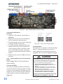
5.1 Internal Jumpers and Settings
The 7114 contains two “daughter card” circuit
boards; each board connects to the main board
through two 20-pin, non-locking connectors. All
advanced conguration settings are made on the
outer-most daughter card, labeled “7100 Control-
ler.”
5.1.1 Removing the 7100 Controller
Circuit Board
Top Cover Removal
Tool Required
#1 Phillips screwdriver
Procedure
Figure 5.1 – Cover Screw Locations
1. Remove power from the unit and disconnect
any load from the outputs. Wait a minimum of
three minutes to allow the unit’s capacitors to
discharge.
2. Use a #1 Phillips screwdriver to remove the
twelve (12) Phillips-head screws, as shown in
Figure 5.1.
3. Slide the cover towards the back of the unit,
and then lift the cover straight up to remove
and set aside.
4. To replace the top cover, slide the cover in
to place on the unit and replace the twelve
screws.
Figure 5.2 – 7114 Controller Board Location
Uninsulated terminals with AC mains po-
tential are exposed when the top cover
is removed. Do not proceed until the unit
has been turned o and the AC Mains
has been disconnected.
DANGER
After turning the unit o, let the unit
sit for 3-5 minutes before removing the
top cover. This will allow the electrical
charge in the power supply capacitors to
discharge.
CAUTION

Information subject to change
97-8004339_05-08-18
7114 OPERATOR’S MANUAL – SECTION 5
14
Controller Board Removal
Procedure
1. Locate the 7100 Controller card as shown in
Figure 5.2.
2. Remove the two jack nuts from the DB9 Con-
trol Port connector on the back panel.
3. Firmly pull straight up on the card to disconnect
it from the two 20-pin connectors.
4. To replace the board, position the 20-pin con-
nectors located on the 7100 Controller card
over the matching 20-pin connectors located
on the 7100-series main board. Push gently
but rmly to seat the card into place in the con-
nectors.
5. Replace the jack nuts on the DB9 Control Port
connector.
5.1.2 Jumper Settings on the 7100 Controller
Board
Refer to Figure 5.3 for 7100 Controller Board
jumper locations.
Current Limit Eect
The current limit setting (I LIMIT) will aect both
AC and DC waveforms (factory default). To cong-
ure the unit for a current limit that aects only AC
waveforms, move the shunts at jumper J12 to the
positions shown in the AC only setting shown in
Figure 5.4.
Controlled Mode
By default, the 7114 operates in Controlled-Voltage
mode. In Controlled-Voltage mode, the unit’s
output voltage will be controlled by its input volt-
age signal. The 7114 can be congured to operate
In Controlled-Current Mode, the load is part of the amplica-
tion circuit, and the relationship of the load to this circuit is
critical. For proper and safe operation in Controlled-Current
mode, you must observe the following guidelines:
1. Properly attach a load before operating the unit.
2. DO NOT use a blocking capacitor. The load must have a
DC path.
3. Never leave the load open. If you feel the load must be
fused, which could lead to a potential open circuit, please
contact AE Techron Technical Support.
4. Make sure the load has some inductive component.
5. Provide appropriate compensation for the load.
6. If oscillation occurs, turn o the unit immediately.
Failure to follow these guidelines may result
in damage to the amplier or the load.
CAUTION
Figure 5.3 – 7100 Controller Board Jumper Locations
Figure 5.4 – Current Limit Jumper Settings

97-8004339_05-08-18
Information subject to change
15
7114 OPERATOR’S MANUAL – SECTION 5
in Controlled-Current mode. In Controlled-Current
mode, the unit’s output current will be controlled by
its input voltage signal.
IMPORTANT: Controlled-Current operation re-
quires the use of a compensation network, and the
7114’s default compensation network may not be
suitable for your application. For more information
on Controlled-Current operation, including how to
determine and congure a custom compensation
network, see the Applications section.
To congure the amplier for Controlled-Current
operation, locate jumper J4 and remove the shunt
from pins 1 and 2 (factory default). Place the
shunt across pins 2 and 3 to place the product in
Controlled-Current mode.
Compensation Network
When the 7114 is used in Controlled-Current
mode, the current control loop is tuned with an
RC network. The factory default network (CC1)
provides 75k ohm resistance and 47 nF capaci-
tance. If this default network is not adequate for
your application and load, CC2 can be used to
install a custom RC network.
To change the compensation network, locate jump-
er J11. When pins 1 and 2 are shunted (factory
default), network CC1 is enabled (75k ohm and
47 nF). To select network CC2, place the shunt on
jumper J11 across pins 2 and 3.
Remove the shunt from jumper J3 to disable both
CC1 and CC2 networks. A small feedback capaci-
tor remains in the circuit to provide stability when
operating into an 8-ohm load. For more information
on Controlled-Current operation and installing a
custom RC network, see the “Applications” sec-
tion of this manual.
Maximum Oset
When variable DC oset is selected using the
OFFSET button, DC can be oset by ±20V (factory
default). To change the default setting to extend
the maximum variable DC oset to ±45V, remove
the shunt over pins 1 and 2 of jumper J9.
Overload Latch
When an overload condition occurs, the unit’s
OVLD LED will illuminate, but it will continue to
amplify the input signal. To congure the unit to en-
ter Fault mode when an overload condition occurs,
place the shunt over pins 1 and 2 of jumper J6.

Information subject to change
97-8004339_05-08-18
7114 OPERATOR’S MANUAL – SECTION 6
16
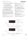
Figure 6.1 – RAIL V Switch Settings Comparison
Figure 6.2 – DB-9 Control Port Pinouts
6 Applications
6.1 RAIL V Settings for Increased
Voltage or Current
The 7114 features a bi-level power supply that
contains two secondary transformers. The second-
ary rails of each transformer can be placed in a
series or parallel conguration, as shown in Figure
6.1, providing the option for operating in High
Voltage mode (increased voltage) or High Current
mode (increased current).
As shipped from the factory, the 7114 is set to oper-
ate with the transformer rails congured in series,
providing a voltage potential of 90V. This congura-
tion works well for high-voltage applications.
For high-current applications requiring a lower
voltage potential, press the RAIL V switch to place
the transformer rails in parallel. This will result in a
maximum voltage potential of 45V.
Refer to the Specications section of this manual
for maximum voltage and current capabilities when
running in High Voltage or High Current modes.
6.2 Remote Status and Control using
the DB-9 Connector
The procedures outlined in this section assume
competence on the part of the reader in terms of
power supplies, amplier systems, electronic com-
ponents, and good electronic safety and working
practices.
AE Techron 7114 ampliers have a DB-9 connec-
tor on the back panel that can be used to provide
remote control and monitoring of the unit.
The information provided here will instruct you in
the wiring of several control and status applica-
tions including:
• Balanced Signal Input
• Remote Emergency Stop/Fast Mute/Blanking
• Fault status
• Current monitor
Figure
6
.2 maps the pins used for these applications.

97-8004339_05-08-18
Information subject to change
17
7114 OPERATOR’S MANUAL – SECTION 6
Figure 6.3 – Balanced Input Wiring
on DB-9 Control Port
Figure 6.4 – Emergency Stop/Fast Mute/Blanking
Application Wiring on DB-9 Control Port
6.2.1 Balanced Signal Input
You can use the DB-9 Control Port located on the
back panel of the unit as an additional balanced
signal input. This input can be used simultaneously
with the front panel unbalanced BNC and/or bal-
anced WECO inputs.
Signal Input
Purpose: Use the DB-9 Control Port as an alter-
nate or additional signal input.
Method: Connect to your signal input device using
Pin 1 (signal +), Pin 2 (signal –) and Pin 3 (ground)
to a DB-9 connector. See Figure 6.3.
Signal Type: AC
Level when Asserted: 10 V maximum
Level when Deasserted: 0 V
6.2.2 Emergency Stop/Fast Mute/Blanking
Purpose: Use switch or optocoupler to remotely
mute the unit.
Method: Assert 5-15VDC between Pin 5 (Blanking
Ground) and Pin 4 (Blanking Input) to activate the
blanking feature. See Figure 6.4.
Signal Type: DC
Level when Asserted: 5 - 15V
Level when Deasserted: 0V
Note: The unit’s output is muted when asserted.
Normal operation when deasserted.
Blanking input is opto-isolated and requires a
ground which Pin 5 (Blanking Ground) provides.
6.2.3 Remote Fault Status Monitor
Using the DB-9 Control Port located on the back
panel, you can remotely monitor the Fault status of
the unit.
Remote Fault Status
Purpose: Remote LED, when lit, signals a Fault
condition.
Method: Supply 5-15VDC to an LED between Pin
7 (Fault Ground) and Pin 6 (Fault). See Figure
6.5.
Signal Type: DC
Level when Asserted: Closed through 2 kΩ resis-
tor.
Level when Deasserted: Open
Note: Internal 2 kΩ resistor is in series with an
opto-isolated transistor that acts as a switch for
Fault status. The Fault input is opto-isolated and
requires a ground which Pin 7 (Fault Ground)
provides.
Figure 6.5 – Remote Fault Monitor
Application Wiring on DB-9 Control Port

Information subject to change
97-8004339_05-08-18
7114 OPERATOR’S MANUAL – SECTION 6
18
6.2.4 Remote Current Monitor
Using the DB-9 Control Port located on the back
panel, you can remotely monitor the current output
of the unit.
Remote Monitoring of Current Output
Purpose: Use a voltage meter to monitor output
current.
Method: Connect a voltage meter to monitor the
output current being produced by the unit. Con-
nect across PIN 8 (I MON+) and PIN 9 (Analog
Ground). See Figure 6.6.
Signal Type: AC & DC
Level: 5A/V
6.3 Controlled Current Operation
The procedures outlined in this section assume
competence on the part of the reader in terms of
power supplies, amplier systems, electronic com-
ponents, and good electronic safety and working
practices.
6.3.1 Controlled-Voltage vs. Controlled-
Current Modes of Operation
AE Techron 7114 amplier can be eld-congured
to operate as a Voltage Amplier (Voltage-Con-
trolled Voltage Source) or as a Transconductance
Amplier (Voltage-Controlled Current Source).
The mode selection is made via jumpers on the
unit’s controller daughter card. See the Advanced
Conguration section for more information.
When congured as a Controlled-Voltage source
(voltage amplier), the amplier will provide an
output voltage that is constant and proportional
to the control (input) voltage. If the load’s imped-
ance changes, the amplier will seek to maintain
this ratio of input to output voltage by increasing or
decreasing the current it produces, as long as it is
within the amplier’s ability to create the required
current. Use this mode if you want the output volt-
age waveform to be like the input waveform (see
Figure 6.7).
Conversely, when congured as a Controlled-
Current source (transconductance amplier), the
amplier will provide an output current that is con-
stant and proportional to the control (input) volt-
age. If the load’s impedance changes, the amplier
will seek to maintain this transconductance (ratio
of input voltage to output current) by increasing or
decreasing the voltage it produces, as long as it is
within the amplier’s ability to create the required
voltage. Use this mode if you want the output cur-
rent waveform to be like the input waveform (see
Figure 6.8).
Figure 6.6 – Remote Current Monitor
Application Wiring on DB-9 Control Port
Figure 6.7 – Input to Output Comparison,
Controlled-Voltage Operation
Figure 6.8 – Input to Output Comparison,
Controlled-Current Operation

97-8004339_05-08-18
Information subject to change
19
7114 OPERATOR’S MANUAL – SECTION 6
6.3.2 Safety and Operation Considerations for
Controlled Current Operation
When an AE Techron 7114 amplier is congured
as a Controlled-Current source, care needs to
be exercised in its operation. Any voltage con-
trolled current source should never be turned
on without a load, (with some impedance, real
or eective) connected to its output terminals.
When asked to operate in this way, any current
source (including an AE Techron amplier) will in-
crease its output voltage in an attempt to drive the
requested current into the load. In an open-circuit
condition, creating current ow will be impossible.
The current source will increase its output voltage
until it reaches its voltage limit. This is a potentially
dangerous condition for both the AE Techron am-
plier and for any user who might come in contact
with the amplier’s output terminals.
When operating in Controlled-Current (CC) mode,
a compensation circuit is required to ensure ac-
curate output current. Since the load is a critical
circuit component in CC mode, the inductive and
resistive values of the load will determine the
required compensation values. While the factory-
default compensation setting will be sucient
for some applications, the compensation setting
may also be adjusted in the eld. The following
section describes methods for determining and
setting proper compensation when operating in
Controlled-Current mode.
6.3.3 Controlling Compensation for CC
Operation
The AE Techron 7114 amplier can be congured
for either Controlled Voltage (CV) or Controlled
Current (CC) mode of operation. When operat-
ing the amplier in Controlled Voltage (CV) mode,
compensation is not required. However, when op-
erating in Controlled Current (CC) mode, the load
becomes an integral part of the system. In order
to ensure system stability and to control available
bandwidth, compensation via an RC network is
required for CC operation. The following steps will
allow you to compensate your unit for operation in
CC mode safely and eectively.
We recommend that you power-up and enable
the amplier in Controlled Voltage mode without
attaching a load before conguring for Controlled
Current operation. This will allow you to verify that
the input signal and the amplier are operating
correctly.
Once this initial check is completed, power down
the amplier, attach your load, and locate and put
the shunt on Jumper J4 on the Controller daughter
card across pins 2 and 3 to place the unit in CC
mode. (Refer to the Advanced Conguration
section for more information.)
When operating an amplier in Controlled-Current
mode, the load becomes an integral part of the
system. In order to determine the required com-
pensation for your load, begin by consulting the
following table to determine the approximate com-
pensation capacitance (C) required based on the
inductance of your load. Note that these calcula-
tions are based on empirical measurements and
are approximent.
STEP 1: Check Amplier Operation in CV mode.
STEP 2: Determine Required Compensation.
Load Inductance (L)
<200 µH >200 µH – <1 mH >1 mH
Compensation Capacitance (CC) 0.001 µF 0.01 µF 0.1 µF
NOTE: Load Resistance (R) is assumed to be <5 ohms.

Information subject to change
97-8004339_05-08-18
7114 OPERATOR’S MANUAL – SECTION 6
20
If your load inductance is between 200 microHen-
ries and 1 milliHenry, and your load resistance
is less than 5 ohms, then you can likely use the
default compensation provided by the amplier’s
factory-installed RC network. This compensation
network is enabled by default when the Current
setting is selected on the Controlled Mode jumper.
If your load inductance falls outside of the mid-
range, or if your load resistance is greater than
5 ohms, then you must calculate your required
compensation. If, after calculating your required
compensation, you determine that the default com-
pensation will be insucient for your load, then you
will need to calculate and then enable and install a
custom RC network. See STEP 5 below.
STEP 3: Determine if Default or Custom Compensation is Required.
STEP 4: (Optional) Verify Suitability of Default Compensation (CC1)
If desired, the following values of the components
contained in the default RC network can be used
with the formulas provided in STEP 5 below to
verify the suitability of the default compensation for
your uses.
Compensation Resistor: 75k ohms
Compensation Capacitor: 47 nF
Parallel Capacitor: 100 pF
STEP 5: Calculating Values for an RC Network for Custom Compensation
If the default RC network does not provide suitable
compensation for your intended load, you will need
to install a custom RC network that is matched
to your load. This network will require two com-
ponents (a resistor (R) and a capacitor (C)) to be
installed on the unit’s Controller daughter card. To
calculate the approximate values required for each
component, use the following fomulas.
COMPENSATION FORMULAS:
To nd the value for the resistor (Rc) in the RC
network: Rc = 20,000 x 3.14 x L x BW
where:
Rc is compensation resistance in ohms.
L is load inductance in henries.
BW is bandwidth in hertz.
To nd the value for the capacitor (Cc) in the
RC network: Cc = L/ (R x Rc)
where:
Cc is compensation capacitance in farads.
L is load inductance in henries.
R is resistance of load in ohms.
Rc is compensation resistance in ohms.
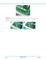
STEP 6: Installing and Enabling the Custom RC Network
Once an approximate Rc and Cc have been com-
puted, these values will need to be evaluated. To
do this, you will need to install the custom compo-
nents in the unit and enable the alternate compe-
nation network (CC2).
Refer to the topic “Internal Jumpers and Set-
tings” in the Advanced Conguration section
of this manual for instructions on accessing the
Controller daughter board in the amplier. Then
locate jumper J11, and remove the shunt from
pins 1 and 2. Replace the shunt on pins 2 and
3 of jumper J3 to enable the custom RC network
pathway (CC2).
Next, install components with the required values
in the Controller daughter board at locations R5
and C2 as shown in Figure 6.9.
Page is loading ...
Page is loading ...
Page is loading ...
Page is loading ...
Page is loading ...
Page is loading ...
Page is loading ...
Page is loading ...
Page is loading ...
Page is loading ...
Page is loading ...
Page is loading ...
Page is loading ...
-
 1
1
-
 2
2
-
 3
3
-
 4
4
-
 5
5
-
 6
6
-
 7
7
-
 8
8
-
 9
9
-
 10
10
-
 11
11
-
 12
12
-
 13
13
-
 14
14
-
 15
15
-
 16
16
-
 17
17
-
 18
18
-
 19
19
-
 20
20
-
 21
21
-
 22
22
-
 23
23
-
 24
24
-
 25
25
-
 26
26
-
 27
27
-
 28
28
-
 29
29
-
 30
30
-
 31
31
-
 32
32
-
 33
33


Ask a question and I''ll find the answer in the document
Finding information in a document is now easier with AI
Related papers
Other documents
-
 Victron Filax 2 Ultra Fast AC Transfer Switch Installation guide
-
 ALEKTO 6801 User manual
-
Aplex AEx-915AP User manual
-
Aplex ViTAM-919AR User manual
-
-
Aplex FABS-921AP User manual
-
Aplex ARCHMI-916AGH User manual
-
-
-
 DeLuxe Stitcher M7-AST-19x21-1/2 Operation and Maintenance Manual


