Danfoss ECL Comfort 310, A361 Operating instructions
- Type
- Operating instructions

OperatingGuide
ECLComfort310,applicationA361
1.0TableofContents
1.0TableofContents...............................................1
1.1Importantsafetyandproductinformation.....................2
2.0Installation........................................................5
2.1Beforeyoustart.....................................................5
2.2Identifyingthesystemtype.......................................9
2.3Mounting...........................................................10
2.4Placingthetemperaturesensors................................14
2.5Electricalconnections.............................................16
2.6InsertingtheECLApplicationKey..............................24
2.7Checklist............................................................30
2.8Navigation,ECLApplicationKeyA361.........................31
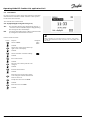
3.0Dailyuse.........................................................34
3.1Howtonavigate...................................................34
3.2Understandingthecontrollerdisplay..........................35
3.3Ageneraloverview:Whatdothesymbolsmean?...........37
3.4Monitoringtemperaturesandsystem
components........................................................38
3.5Influenceoverview................................................39
3.6Manualcontrol.....................................................40
3.7Schedule............................................................41
4.0Settingsoverview............................................42
5.0Settings...........................................................44
5.1IntroductiontoSettings..........................................44
5.2Flowtemperature..................................................45
5.3Returnlimit.........................................................50
5.4Flow/powerlimit.................................................54
5.5Optimization........................................................58
5.6Controlparameters................................................64
5.7Pumpcontrol.......................................................68
5.8Refillwater..........................................................71
5.9Application.........................................................76
5.10Alarm................................................................81
5.11Alarmoverview....................................................84
6.0Commoncontrollersettings..............................85
6.1Introductionto‘Commoncontrollersettings’................85
6.2Time&Date.........................................................86
6.3Holiday..............................................................87
6.4Inputoverview.....................................................89
6.5Log...................................................................90
6.6Outputoverride....................................................91
6.7Keyfunctions.......................................................92
6.8System...............................................................94
7.0Miscellaneous................................................101
7.1ECA30/31setupprocedures.................................101
7.2Overridefunction................................................109
7.3Severalcontrollersinthesamesystem......................112
7.4Frequentlyaskedquestions....................................115
7.5Definitions........................................................118
7.6Type(ID6001),overview.......................................121
7.7ParameterIDoverview..........................................122
©Danfoss|2017.10VI.LG.M2.02|1

1.1Importantsafetyandproductinformation
1.1.1Importantsafetyandproductinformation
ThisInstallationGuideisassociatedwithECLApplicationKeyA361
(ordercodeno.087H3804).
ThefunctionscanberealizedwithECLComfort310.
TheapplicationA361complieswithECLComfortcontroller310as
ofsoftwareversion1.10(visibleatstart-upofthecontrollerandin
‘Commoncontrollersettings’in‘System’).
AdditionaldocumentationforECLComfort210and310,modules
andaccessoriesisavailableonhttp://heating.danfoss.com/.
Applicationkeysmightbereleasedbeforealldisplaytextsare
translated.InthiscasethetextisinEnglish.
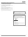
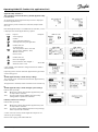
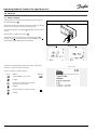
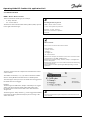
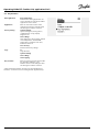
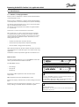
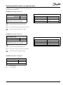
Automaticupdateofcontrollersoftware(firmware):
Thesoftwareofthecontrollerisupdatedautomaticallywhenthekey
isinserted(asofcontrollerversion1.11(ECL210/310)andversion
1.58(ECL296)).Thefollowinganimationwillbeshownwhenthe
softwareisbeingupdated:
Progressbar
Duringupdate:
•DonotremovetheKEY
Ifthekeyisremovedbeforethehour-glassisshown,youhave
tostartafresh.
•Donotdisconnectthepower
Ifthepowerisinterruptedwhenthehour-glassisshown,the
controllerwillnotwork.
2|©Danfoss|2017.10
VI.LG.M2.02
OperatingGuideECLComfort310,applicationA361

SafetyNote
Toavoidinjuryofpersonsanddamagestothedevice,itisabsolutely
necessarytoreadandobservetheseinstructionscarefully.
Necessaryassembly,start-up,andmaintenanceworkmustbe
performedbyqualifiedandauthorizedpersonnelonly.
Locallegislationsmustberespected.Thiscomprisesalsocable
dimensionsandtypeofisolation(doubleisolatedat230V).
AfusefortheECLComfortinstallationismax.10Atypically.
TheambienttemperaturerangesforECLComfortinoperationare:
ECLComfort210/310:0-55°C
ECLComfort296:0-45°C.
Exceedingthetemperaturerangecanresultinmalfunctions.
Installationmustbeavoidedifthereisariskforcondensation(dew).
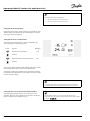
Thewarningsignisusedtoemphasizespecialconditionsthatshould
betakenintoconsideration.
Thissymbolindicatesthatthisparticularpieceofinformationshould
bereadwithspecialattention.
AsthisOperatingGuidecoversseveralsystemtypes,specialsystem
settingswillbemarkedwithasystemtype.Allsystemtypesareshown
inthechapter:'Identifyingyoursystemtype'.
°C(degreesCelsius)isameasuredtemperaturevaluewhereasK
(Kelvin)oftenisusedfortemperaturedifferences.
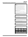
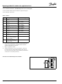
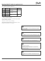
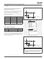
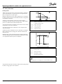
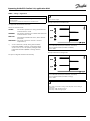
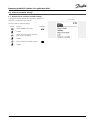
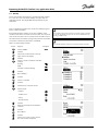
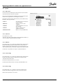
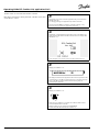
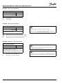
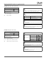
TheIDno.isuniquefortheselectedparameter.
ExampleFirstdigitSeconddigitLastthreedigits
1117411174
-
Circuit1
Parameterno.
12174
1
2
174
-
Circuit2
Parameterno.
IfanIDdescriptionismentionedmorethanonce,itmeansthatthere
arespecialsettingsforoneormoresystemtypes.Itwillbemarked
withthesystemtypeinquestion(e.g.12174-A266.9).
VI.LG.M2.02
©Danfoss|2017.10|3
OperatingGuideECLComfort310,applicationA361

ParametersindicatedwithanIDno.like"1x607"meanauniversal
parameter.
xstandsforcircuit/parametergroup.
DisposalNote
Thisproductshouldbedismantledanditscomponents
sorted,ifpossible,invariousgroupsbeforerecycling
ordisposal.
Alwaysfollowthelocaldisposalregulations.
4|©Danfoss|2017.10
VI.LG.M2.02
OperatingGuideECLComfort310,applicationA361

2.0Installation
2.1Beforeyoustart
TheapplicationA361.1isveryflexible.Thesearethebasic
principles:
Heating(circuit1and2):
Typically,theflowtemperatureisadjustedaccordingtoyour
requirements.TheflowtemperaturesensorS3(circuit1)and
S4(circuit2)arethemostimportantsensors.Thedesiredflow
temperaturesatS3andS4arecalculatedintheECLcontroller,
basedontheoutdoortemperature(S1).Thelowertheoutdoor
temperature,thehigherthedesiredflowtemperature.
Bymeansofaweekschedule,theheatingcircuitcanbein
‘Comfort’or‘Saving’mode(twodifferenttemperaturevaluesfor
desiredroomtemperature).
ThemotorizedcontrolvalvesM1(circuit1)andM2(circuit2)are
openedgraduallywhentheflowtemperatureislowerthanthe
desiredflowtemperatureandviceversa.
ThereturntemperaturesS5(circuit1)andS6(circuit2)tothe
districtheatingsupplyshouldnotbetoohigh.Ifso,thedesired
flowtemperaturecanbeadjusted(typicallytoalowervalue),thus
resultinginagradualclosingofthemotorizedcontrolvalves.
Inboiler-basedheatingsupplythereturntemperatureshouldnot
betoolow(sameadjustmentprocedureasabove).
Furthermore,thereturntemperaturelimitationcanbedependent
oftheoutdoortemperature.Typically,thelowertheoutdoor
temperature,thehighertheacceptedreturntemperature.
ThecirculationpumpinquestionisONatheatdemandoratfrost
protection.
TheheatingcanbeswitchedOFFwhentheoutdoortemperatureis
higherthanaselectablevalue.
Thestaticpressureonthesecondaryside(consumerside)can1)
bemeasuredasa0-10Vsignal(fromapressuretransmitter)or
2)beaswitchsignalfromapressureswitch.Incaseofatoolow
pressure,therefillwaterfunctionwillsupplementwithwaterfrom
thesupplyside.
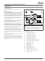
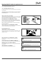
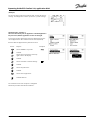
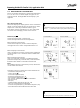
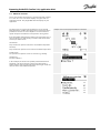
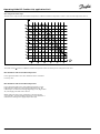
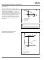
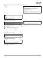
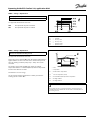
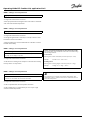
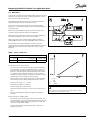
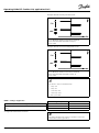
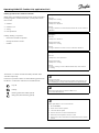
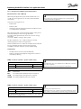
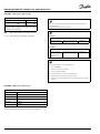
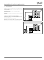
TypicalA361.1application:
Theshowndiagramisafundamentalandsimplifiedexampleanddoes
notcontainallcomponentsthatarenecessaryinasystem.
AllnamedcomponentsareconnectedtotheECLComfortcontroller.
Listofcomponents:
S1
Outdoortemperaturesensor
S3
Flowtemperaturesensor,circuit1
S4
Flowtemperaturesensor,circuit2
S5
Returntemperaturesensor,circuit1
S6
Returntemperaturesensor,circuit2
S7
Differentialpressureswitch,circuit1
S8
Differentialpressureswitch,circuit2
S9
Pressuretransmitterorpressureswitch,circuit2
S10
Pressuretransmitterorpressureswitch,circuit1
P1
Circulationpump,circuit1
P2
Circulationpump,circuit1
P3
Circulationpump,circuit2
P4
Refillwaterpump
P5
Circulationpump,circuit2
M1
Motorizedcontrolvalve,circuit1
M2
Motorizedcontrolvalve,circuit2
V1
Solenoidvalve,circuit1,refillwatervalve
V2
Solenoidvalve,circuit2,refillwatervalve
R6
Relayoutput,alarm
VI.LG.M2.02
©Danfoss|2017.10|5
OperatingGuideECLComfort310,applicationA361

ApplicationA361.1ingeneral:
ThecirculationpumpsP1andP2(circuit1)/P3andP5(circuit2)
workinshiftaccordingtoaschedule.Onepumpisusedasspare
pumpandtheotherpumpisworking.Incaseofmalfunction
(missingdifferentialpressure)ofonepump,theotherpumpwill
takeover.Analarmwillbegeneratedandthedefectivepumpcan
beinspected/repaired.
Alarm(relay6)canbeactivatedif:
•Theactualflowtemperaturediffersfromthedesiredflow
temperature.
•Theactivatedcirculationpumpdoesnotgenerateapressure
difference.
•Therefillwaterfunctiondoesnotgenerateapressurewithin
apresettime.
ModbuscommunicationtoaSCADAsystemcanbeestablished.
M-buscommunicationenablesconnectiontofloworenergymeter.
Thecontrollercanlimitthefloworenergytoasetmaximumbut
alsoinrelationtotheoutdoortemperature.
Furthermore,theM-busdatacanbetransferredtotheModbus
communication.
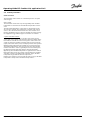
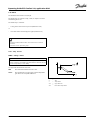
TypicalA361.1application:
6|©Danfoss|2017.10
VI.LG.M2.02
OperatingGuideECLComfort310,applicationA361

TheapplicationA361.2isveryflexible.Thesearethebasic
principles:
Heating(circuit1and2):
Typically,theflowtemperatureisadjustedaccordingtoyour
requirements.TheflowtemperaturesensorS3(circuit1)and
S4(circuit2)arethemostimportantsensors.Thedesiredflow
temperaturesatS3andS4arecalculatedintheECLcontroller,
basedontheoutdoortemperature(S1).Thelowertheoutdoor
temperature,thehigherthedesiredflowtemperature.
Thesupplytemperature(S2)isusedto1)controltheS3andS4
temperaturesinrelationtotheS2temperatureor2)maximizethe
limitofthedesiredflowtemperature.
Thefactorysetting,wherethesupplytemperature(S2)determines
thedesiredflowtemperature,doesnotchangethedesiredflow
temperatureaccordingto‘Comfort’or‘Saving’mode.
However,ifthesupplytemperature(S2)determinesamax.
limitationofthedesiredflowtemperature,the‘Comfort’and
‘Saving’modewillhavetwodifferenttemperaturevaluesfor
desiredroomtemperature.
ThemotorizedcontrolvalvesM1(circuit1)andM2(circuit2)are
openedgraduallywhentheflowtemperatureislowerthanthe
desiredflowtemperatureandviceversa.
ThereturntemperaturesS5(circuit1)andS6(circuit2)tothe
districtheatingsupplyshouldnotbetoohigh.Ifso,thedesired
flowtemperaturecanbeadjusted(typicallytoalowervalue),thus
resultinginagradualclosingofthemotorizedcontrolvalves.
Inboiler-basedheatingsupplythereturntemperatureshouldnot
betoolow(sameadjustmentprocedureasabove).
Furthermore,thereturntemperaturelimitationcanbedependent
oftheoutdoortemperature.Typically,thelowertheoutdoor
temperature,thehighertheacceptedreturntemperature.
ThecirculationpumpinquestionisONatheatdemandoratfrost
protection.
TheheatingcanbeswitchedOFFwhentheoutdoortemperatureis
higherthanaselectablevalue.
Thestaticpressureonthesecondaryside(consumerside)can1)
bemeasuredasa0-10Vsignal(fromapressuretransmitter)or
2)beaswitchsignalfromapressureswitch.Incaseofatoolow
pressure,therefillwaterfunctionwillsupplementwithwaterfrom
thesupplyside.
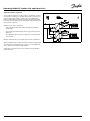
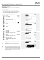
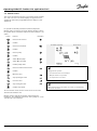
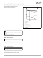
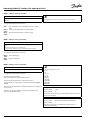
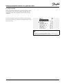
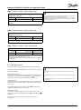
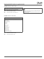
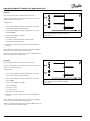
TypicalA361.2application:
Theshowndiagramisafundamentalandsimplifiedexampleanddoes
notcontainallcomponentsthatarenecessaryinasystem.
AllnamedcomponentsareconnectedtotheECLComfortcontroller.
Listofcomponents:
S1
Outdoortemperaturesensor
S2
Supplyflowtemperaturesensor
S3
Flowtemperaturesensor,circuit1
S4
Flowtemperaturesensor,circuit2
S5
Returntemperaturesensor,circuit1
S6
Returntemperaturesensor,circuit2
S7
Differentialpressureswitch,circuit1
S8
Differentialpressureswitch,circuit2
S9
Pressuretransmitterorpressureswitch,circuit2
S10
Pressuretransmitterorpressureswitch,circuit1
P1
Circulationpump,circuit1
P2
Circulationpump,circuit1
P3
Circulationpump,circuit2
P4
Refillwaterpump
P5
Circulationpump,circuit2
M1
Motorizedcontrolvalve,circuit1
M2
Motorizedcontrolvalve,circuit2
V1
Solenoidvalve,circuit1,refillwatervalve
V2
Solenoidvalve,circuit2,refillwatervalve
R6
Relayoutput,alarm
VI.LG.M2.02
©Danfoss|2017.10|7
OperatingGuideECLComfort310,applicationA361

ApplicationA361.2ingeneral:
ThecirculationpumpsP1andP2(circuit1)/P3andP5(circuit2)
workinshiftaccordingtoaschedule.Onepumpisusedasspare
pumpandtheotherpumpisworking.Incaseofmalfunction
(missingdifferentialpressure)ofonepump,theotherpumpwill
takeover.Analarmwillbegeneratedandthedefectivepumpcan
beinspected/repaired.
Alarm(relay6)canbeactivatedif:
•Theactualflowtemperaturediffersfromthedesiredflow
temperature.
•Theactivatedcirculationpumpdoesnotgenerateapressure
difference.
•Therefillwaterfunctiondoesnotgenerateapressurewithin
apresettime.
ModbuscommunicationtoaSCADAsystemcanbeestablished.
M-buscommunicationenablesconnectiontofloworenergymeter.
Thecontrollercanlimitthefloworenergytoasetmaximumbut
alsoinrelationtotheoutdoortemperature.
Furthermore,theM-busdatacanbetransferredtotheModbus
communication.
TypicalA361.2application:
Thecontrollerispre-programmedwithfactorysettingsthatareshown
inthe‘ParameterIDoverview’appendix.
8|©Danfoss|2017.10
VI.LG.M2.02
OperatingGuideECLComfort310,applicationA361

2.2Identifyingthesystemtype
Sketchyourapplication
TheECLComfortcontrollerseriesisdesignedforawiderange
ofheating,domestichot-water(DHW)andcoolingsystemswith
differentconfigurationsandcapacities.Ifyoursystemdiffers
fromthediagramsshownhere,youmaywanttomakeasketch
ofthesystemabouttobeinstalled.Thismakesiteasiertouse
theOperatingGuide,whichwillguideyoustep-by-stepfrom
installationtofinaladjustmentsbeforetheend-usertakesover.
TheECLComfortcontrollerisauniversalcontrollerthatcanbe
usedforvarioussystems.Basedontheshownstandardsystems,
itispossibletoconfigureadditionalsystems.Inthischapteryou
findthemostfrequentlyusedsystems.Ifyoursystemisnotquite
asshownbelow,findthediagramwhichhasthebestresemblance
withyoursystemandmakeyourowncombinations.
SeetheInstallationGuide(deliveredwiththeapplicationkey)for
applicationtypes/sub-types.
Thecirculationpump(s)inheatingcircuit(s)canbeplacedintheflow
aswellasthereturn.Placethepumpaccordingtothemanufacturer’s
specification.
VI.LG.M2.02
©Danfoss|2017.10|9
OperatingGuideECLComfort310,applicationA361

2.3Mounting
2.3.1MountingtheECLComfortcontroller
SeetheInstallationGuidewhichisdeliveredtogetherwiththe
ECLComfortcontroller.
Foreasyaccess,youshouldmounttheECLComfortcontrollernear
thesystem.
ECLComfort210/296/310canbemounted
•onawall
•onaDINrail(35mm)
ECLComfort296canbemounted
•inapanelcut-out
ECLComfort210canbemountedinanECLComfort310basepart
(forfutureupgrade).
Screws,PGcableglandsandrawlplugsarenotsupplied.
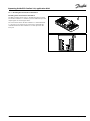
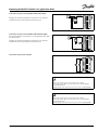
LockingtheECLComfort210/310controller
InordertofastentheECLComfortcontrollertoitsbasepart,secure
thecontrollerwiththelockingpin.
Topreventinjuriestopersonsorthecontroller,thecontrollerhasto
besecurelylockedintothebase.Forthispurpose,pressthelocking
pinintothebaseuntilaclickisheardandthecontrollernolonger
canberemovedfromthebase.
Ifthecontrollerisnotsecurelylockedintothebasepart,thereisarisk
thatthecontrollerduringoperationcanunlockfromthebaseandthe
basewithterminals(andalsothe230Va.c.connections)areexposed.
Topreventinjuriestopersons,alwaysmakesurethatthecontroller
issecurelylockedintoitsbase.Ifthisisnotthecase,thecontroller
shouldnotbeoperated!
10|©Danfoss|2017.10
VI.LG.M2.02
OperatingGuideECLComfort310,applicationA361

Theeasywaytolockthecontrollertoitsbaseorunlockitistousea
screwdriveraslever.
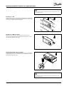
Mountingonawall
Mountthebasepartonawallwithasmoothsurface.Establishthe
electricalconnectionsandpositionthecontrollerinthebasepart.
Securethecontrollerwiththelockingpin.
MountingonaDINrail(35mm)
MountthebasepartonaDINrail.Establishtheelectrical
connectionsandpositionthecontrollerinthebasepart.Secure
thecontrollerwiththelockingpin.
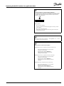
DismountingtheECLComfortcontroller
Inordertoremovethecontrollerfromthebasepart,pulloutthe
lockingpinbymeansofascrewdriver.Thecontrollercannowbe
removedfromthebasepart.
Theeasywaytolockthecontrollertoitsbaseorunlockitistousea
screwdriveraslever.
VI.LG.M2.02
©Danfoss|2017.10|11
OperatingGuideECLComfort310,applicationA361

BeforeremovingtheECLComfortcontrollerfromthebasepart,ensure
thatthesupplyvoltageisdisconnected.
2.3.2MountingtheRemoteControlUnitsECA30/31
Selectoneofthefollowingmethods:
•Mountingonawall,ECA30/31
•Mountinginapanel,ECA30
Screwsandrawlplugsarenotsupplied.
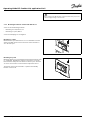
Mountingonawall
MountthebasepartoftheECA30/31onawallwithasmooth
surface.Establishtheelectricalconnections.PlacetheECA30/
31inthebasepart.
Mountinginapanel
MounttheECA30inapanelusingtheECA30framekit(ordercode
no.087H3236).Establishtheelectricalconnections.Securethe
framewiththeclamp.PlacetheECA30inthebasepart.TheECA
30canbeconnectedtoanexternalroomtemperaturesensor.
TheECA31mustnotbemountedinapanelifthehumidity
functionistobeused.
12|©Danfoss|2017.10
VI.LG.M2.02
OperatingGuideECLComfort310,applicationA361

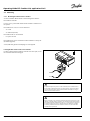
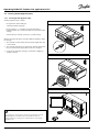
2.3.3MountingtheinternalI/OmoduleECA32
MountingoftheinternalI/OmoduleECA32
TheECA32module(ordercodeno.087H3202)mustbeinserted
intotheECLComfort310/310Bbasepartforadditionalinputand
outputsignalsinrelevantapplications.
TheconnectionbetweentheECLComfort310/310BandECA32
isa10-pole(2x5)connector.Theconnectionisautomatically
establishedwhentheECLComfort310/310Bisplacedonthe
basepart.
VI.LG.M2.02
©Danfoss|2017.10|13
OperatingGuideECLComfort310,applicationA361

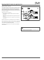
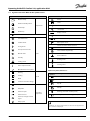
2.4Placingthetemperaturesensors
2.4.1Placingthetemperaturesensors
Itisimportantthatthesensorsaremountedinthecorrectposition
inyoursystem.
Thetemperaturesensormentionedbelowaresensorsusedforthe
ECLComfort210/296/310serieswhichnotallwillbeneeded
foryourapplication!
Outdoortemperaturesensor(ESMT)
Theoutdoorsensorshouldbemountedonthatsideofthebuilding
whereitislesslikelytobeexposedtodirectsunshine.Itshouldnot
beplacedclosetodoors,windowsorairoutlets.
Flowtemperaturesensor(ESMU,ESM-11orESMC)
Placethesensormax.15cmfromthemixingpoint.Insystems
withheatexchanger,DanfossrecommendsthattheESMU-typeto
beinsertedintotheexchangerflowoutlet.
Makesurethatthesurfaceofthepipeiscleanandevenwhere
thesensorismounted.
Returntemperaturesensor(ESMU,ESM-11orESMC)
Thereturntemperaturesensorshouldalwaysbeplacedsothatit
measuresarepresentativereturntemperature.
Roomtemperaturesensor
(ESM-10,ECA30/31RemoteControlUnit)
Placetheroomsensorintheroomwherethetemperatureistobe
controlled.Donotplaceitonoutsidewallsorclosetoradiators,
windowsordoors.
Boilertemperaturesensor(ESMU,ESM-11orESMC)
Placethesensoraccordingtotheboilermanufacturer’s
specification.
Airducttemperaturesensor(ESMB-12orESMUtypes)
Placethesensorsothatitmeasuresarepresentativetemperature.
DHWtemperaturesensor(ESMUorESMB-12)
PlacetheDHWtemperaturesensoraccordingtothemanufacturer’s
specification.
Slabtemperaturesensor(ESMB-12)
Placethesensorinaprotectiontubeintheslab.
ESM-11:Donotmovethesensorafterithasbeenfastenedinorderto
avoiddamagetothesensorelement.
ESM-11,ESMCandESMB-12:Useheatconductingpasteforquick
measurementofthetemperature.
ESMUandESMB-12:Usingasensorpockettoprotectthesensorwill,
however,resultinaslowertemperaturemeasurement.
14|©Danfoss|2017.10
VI.LG.M2.02
OperatingGuideECLComfort310,applicationA361

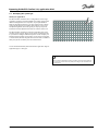
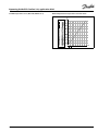
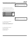
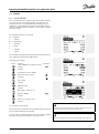
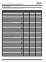
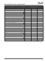
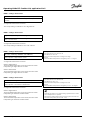
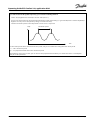
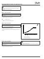
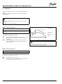
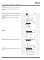
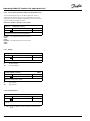
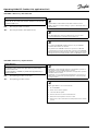
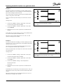
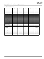
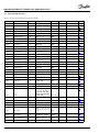
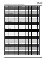
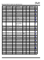
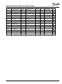
Pt1000temperaturesensor(IEC751B,1000Ω/0°C)
Relationshipbetweentemperatureandohmicvalue:
VI.LG.M2.02
©Danfoss|2017.10|15
OperatingGuideECLComfort310,applicationA361

2.5Electricalconnections
2.5.1Electricalconnections230Va.c.
SafetyNote
Necessaryassembly,start-up,andmaintenanceworkmustbe
performedbyqualifiedandauthorizedpersonnelonly.
Locallegislationsmustberespected.Thiscomprisesalsocablesize
andisolation(reinforcedtype).
AfusefortheECLComfortinstallationismax.10Atypically.
TheambienttemperaturerangefortheECLComfortinoperationis
0-55°C.Exceedingthistemperaturerangecanresultinmalfunctions.
Installationmustbeavoidedifthereisariskforcondensation(dew).
Thecommongroundterminalisusedforconnectionofrelevant
components(pumps,motorizedcontrolvalves).
ECL210/310
ECL296
SeealsotheInstallationGuide(deliveredwiththeapplicationkey)
forapplicationspecificconnections.
16|©Danfoss|2017.10
VI.LG.M2.02
OperatingGuideECLComfort310,applicationA361

Wirecrosssection:0.5-1.5mm²
Incorrectconnectioncandamagetheelectronicoutputs.
Max.2x1.5mm²wirescanbeinsertedintoeachscrewterminal.
Maximumloadratings:
Relayterminals
4(2)A/230Va.c.
(4Aforohmicload,2Afor
inductiveload)
Triac(=electronic
relay)terminals
0,2A/230Va.c.
VI.LG.M2.02
©Danfoss|2017.10|17
OperatingGuideECLComfort310,applicationA361

2.5.2Electricalconnections24Va.c.
SeealsotheInstallationGuide(deliveredwiththeapplicationkey)
forapplicationspecificconnections.
Maximumloadratings:
Relayterminals
4(2)A/24Va.c.
(4Aforohmicload,2Afor
inductiveload)
Triac(=electronic
relay)terminals
1A/24Va.c.
Donotconnect230Va.c.poweredcomponentstoa24Va.c.power
suppliedcontrollerdirectly.Useauxilliaryrelays(K)toseparate230
Va.c.from24Va.c.
18|©Danfoss|2017.10
VI.LG.M2.02
OperatingGuideECLComfort310,applicationA361

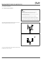
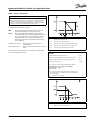
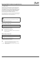
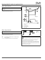
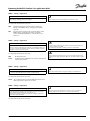
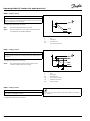
2.5.3Electricalconnections,safetythermostats,ingeneral
SeealsotheInstallationGuide(deliveredwiththeapplicationkey)
forapplicationspecificconnections.
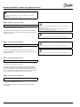
WhenSTisactivatedbyahightemperature,thesafetycircuitinthe
motorizedcontrolvalveclosesthevalveimmediately.
WhenST1isactivatedbyahightemperature(theTRtemperature),the
motorizedcontrolvalveisclosedgradually.Atahighertemperature
(theSTtemperature),thesafetycircuitinthemotorizedcontrolvalve
closesthevalveimmediately.
VI.LG.M2.02
©Danfoss|2017.10|19
OperatingGuideECLComfort310,applicationA361

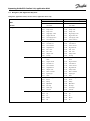
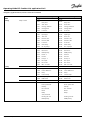
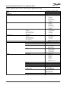
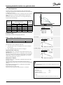
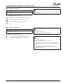
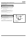
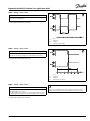
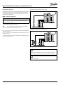
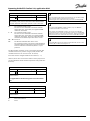
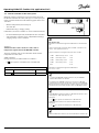
2.5.4Electricalconnections,Pt1000temperaturesensorsandsignals
SeetheInstallationGuide(deliveredwiththeapplicationkey)for
sensorandinputconnections.
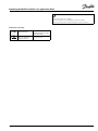
A361.1/A361.2:
Sensor
Description
Recommendedtype
S1
Outdoortemperature
sensor*
ESMT
S2
Supplyflowtemperature
sensor**
ESM-11/ESMB/
ESMC/ESMU
S3
Flowtemperaturesensor***,
circuit1
ESM-11/ESMB/
ESMC/ESMU
S4
Flowtemperaturesensor***,
circuit2
ESM-11/ESMB/
ESMC/ESMU
S5
Returntemperaturesensor,
circuit1
ESM-11/ESMB/
ESMC/ESMU
S6
Returntemperaturesensor,
circuit2
ESM-11/ESMB/
ESMC/ESMU
S7
Differentialpressureswitch,
circuit1
S8
Differentialpressureswitch,
circuit2
S9Pressuretransmitter(0–10
Vor4–20mA)orpressure
switch,circuit2
S10Pressuretransmitter(0–10
Vor4–20mA)orpressure
switch,circuit1
*
Iftheoutdoortemperaturesensorisnotconnectedorthe
cableisshort-circuited,thecontrollerassumesthatthe
outdoortemperatureis0(zero)°C.
**
OnlyforapplicationA361.2.
***
Theflowtemperaturesensormustalwaysbeconnected
inordertohavethedesiredfunctionality.Ifthesensoris
notconnectedorthecableisshort-circuited,themotorized
controlvalvecloses(safetyfunction).
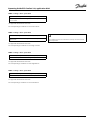
Connectionof2differentialpressureswitches
20|©Danfoss|2017.10
VI.LG.M2.02
OperatingGuideECLComfort310,applicationA361
Page is loading ...
Page is loading ...
Page is loading ...
Page is loading ...
Page is loading ...
Page is loading ...
Page is loading ...
Page is loading ...
Page is loading ...
Page is loading ...
Page is loading ...
Page is loading ...
Page is loading ...
Page is loading ...
Page is loading ...
Page is loading ...
Page is loading ...
Page is loading ...
Page is loading ...
Page is loading ...
Page is loading ...
Page is loading ...
Page is loading ...
Page is loading ...
Page is loading ...
Page is loading ...
Page is loading ...
Page is loading ...
Page is loading ...
Page is loading ...
Page is loading ...
Page is loading ...
Page is loading ...
Page is loading ...
Page is loading ...
Page is loading ...
Page is loading ...
Page is loading ...
Page is loading ...
Page is loading ...
Page is loading ...
Page is loading ...
Page is loading ...
Page is loading ...
Page is loading ...
Page is loading ...
Page is loading ...
Page is loading ...
Page is loading ...
Page is loading ...
Page is loading ...
Page is loading ...
Page is loading ...
Page is loading ...
Page is loading ...
Page is loading ...
Page is loading ...
Page is loading ...
Page is loading ...
Page is loading ...
Page is loading ...
Page is loading ...
Page is loading ...
Page is loading ...
Page is loading ...
Page is loading ...
Page is loading ...
Page is loading ...
Page is loading ...
Page is loading ...
Page is loading ...
Page is loading ...
Page is loading ...
Page is loading ...
Page is loading ...
Page is loading ...
Page is loading ...
Page is loading ...
Page is loading ...
Page is loading ...
Page is loading ...
Page is loading ...
Page is loading ...
Page is loading ...
Page is loading ...
Page is loading ...
Page is loading ...
Page is loading ...
Page is loading ...
Page is loading ...
Page is loading ...
Page is loading ...
Page is loading ...
Page is loading ...
Page is loading ...
Page is loading ...
Page is loading ...
Page is loading ...
Page is loading ...
Page is loading ...
Page is loading ...
Page is loading ...
Page is loading ...
Page is loading ...
Page is loading ...
Page is loading ...
Page is loading ...
-
 1
1
-
 2
2
-
 3
3
-
 4
4
-
 5
5
-
 6
6
-
 7
7
-
 8
8
-
 9
9
-
 10
10
-
 11
11
-
 12
12
-
 13
13
-
 14
14
-
 15
15
-
 16
16
-
 17
17
-
 18
18
-
 19
19
-
 20
20
-
 21
21
-
 22
22
-
 23
23
-
 24
24
-
 25
25
-
 26
26
-
 27
27
-
 28
28
-
 29
29
-
 30
30
-
 31
31
-
 32
32
-
 33
33
-
 34
34
-
 35
35
-
 36
36
-
 37
37
-
 38
38
-
 39
39
-
 40
40
-
 41
41
-
 42
42
-
 43
43
-
 44
44
-
 45
45
-
 46
46
-
 47
47
-
 48
48
-
 49
49
-
 50
50
-
 51
51
-
 52
52
-
 53
53
-
 54
54
-
 55
55
-
 56
56
-
 57
57
-
 58
58
-
 59
59
-
 60
60
-
 61
61
-
 62
62
-
 63
63
-
 64
64
-
 65
65
-
 66
66
-
 67
67
-
 68
68
-
 69
69
-
 70
70
-
 71
71
-
 72
72
-
 73
73
-
 74
74
-
 75
75
-
 76
76
-
 77
77
-
 78
78
-
 79
79
-
 80
80
-
 81
81
-
 82
82
-
 83
83
-
 84
84
-
 85
85
-
 86
86
-
 87
87
-
 88
88
-
 89
89
-
 90
90
-
 91
91
-
 92
92
-
 93
93
-
 94
94
-
 95
95
-
 96
96
-
 97
97
-
 98
98
-
 99
99
-
 100
100
-
 101
101
-
 102
102
-
 103
103
-
 104
104
-
 105
105
-
 106
106
-
 107
107
-
 108
108
-
 109
109
-
 110
110
-
 111
111
-
 112
112
-
 113
113
-
 114
114
-
 115
115
-
 116
116
-
 117
117
-
 118
118
-
 119
119
-
 120
120
-
 121
121
-
 122
122
-
 123
123
-
 124
124
-
 125
125
-
 126
126
-
 127
127


Danfoss ECL Comfort 310, A361 Operating instructions
- Type
- Operating instructions
Ask a question and I''ll find the answer in the document
Finding information in a document is now easier with AI
Related papers
-
Danfoss ECA 30 Installation guide
-
Danfoss ECL 9304 Operating instructions
-
-
-
-
-
-
-
-
Danfoss 080Z4009 User guide
Other documents
-
Raypak PS270VSP User guide
-
OUMAN S203 User manual
-
OUMAN H23 User manual
-
-
-
-
 Simplex RTL-TH DIGITAL Installation And Operating Instructions Manual
-
Shure SW6000-ECA User guide
-
UNI-T A12T User manual
-
Gossen MetraWatt U1600 Operating instructions
