Page is loading ...

Page 1
PARTS LIST
Item # Qty Part # Description
1 1 200813 Sled - Black
2 1 201135 Tent - XT X-Over Cabin
3 1 201232 Frame Bracket “A”
4 1 201233 Frame Bracket “B”
5 1 201207 Back Adjustable Pole
6 1 200491 Top Back Support Pole
7 1 201405 Top Front Support Pole - Adjustable
8 1 200362 Front Adjustable Support Pole
9 2 201208 Left Side Back and Center Elbow and Extension
10 2 201209 Right Side Back and Center Elbow and Extension
11 1 201210 Left Side Front Elbow and Extension
12 1 201211 Right Side Front Elbow and Extension
13 1 201403 Left Side Bottom Elbow and Extension
14 1 201404 Right Side Bottom Elbow and Extension
15 3 201214 Middle Main Frame
15a 1 201378 Middle Main Frame with Pivot
16 6 200195 Black End Cap
17 4 200615 5/16” Washer
18 10 400648 1/4 Nylon Hex Lock Nut
19 30 200942 3/8” Self Tapping Screw
20 1 200980 Plastic Trim Lock Kit
21 1 201369 Quick Switch Braket Kit
Otter XT X-Over Cabin
Installation and Set-Up Instructions
Otter XT X-Over Cabin
Fits Medium Otter XT Sled Only
Parts Identifi cation and Check List
MODEL NUMBERS:
Complete Pkg Otter XT X-Over Cabin 201176 2
1
5
6
7
8
34
16 17 18 2019
13
14
15
9
10 11
12
15a
21

Page 2
Tools Required:
7/16” Box End Wrench 7/16” Drill Bit
7/16” Socket and Ratchet 5/16” Drill Bit
Drill/Driver
Phillips Bit
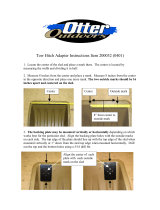
1. Position sled (Item 1) as shown in
Diagram 1, with curved front to
your left.
2. Tip sled on its side and drill the
12 premarked holes using a
5/16” drill bit.
3. Using the premarked hole, drill
the 7/16 in. hole in center of lip
approximately 16 inches from
bend in sled. The back wind
support bar (Item 5 not shown) is
to be propped here.
4. Bolt frame brackets (Item 3 and Item 4) to sled using holes predrilled in Step 2.
Use appropriate fasteners shown in Diagram 2.
Drill 4 premarked
holes with 5/16”
drill bit Drill 4 premarked
bench bracket holes
with 5/16” drill bit
7/16 in.
Hole
Drill 4 premarked
bench bracket holes
with 5/6” drill bit
Diagram 1
Diagram 2
Item 17 - 5/16” Washer
Item 18 - 1/4” Nylon Hex Lock Nut
Note: Install bench seat before the fi sh house framework.
17
1
16 in.
18
4
3

Page 3
5. Position middle main frame (Item 15), left side back and center elbow and extension (Item 9), and right side back
and center elbow and extension (Item 10) as shown. Align locking mechanism in item 15 with square cutout in
items 9 and 10 and slide together until they lock. Repeat this procedure to create another main frame bar.
9
Note: Use a light oil such as WD-
40 to lubricate the bars to help
them slide together easier. Wipe
off any excess. Silicone may be
substituted but is not as eff ective.
10
15
(preassembled)
(preassembled)
Square cutout
Locking mechanism
6. Position middle main frame with pivot (Item 15a), left side front elbow and extension (Item 11), and right side
front elbow and extension (Item 12) as shown. Align locking mechanism in item 15a with square cutout in items
11 and 12 and slide together until they lock. Lubricate frame bars for best operation as shown in step 5.
11
12
15a
(preassembled)
(preassembled)
Square cutout
Locking mechanism
Note: Use a light oil such as WD-40
to lubricate the bars to help them slide
together easier. Wipe off any excess. A dry
lubricant with tefl on works very well.
Note: This assembly is for the Front Main Frame Bar.
Note: These two assemblies are for the Back and Center Main Frame Bars.
Small
lubrication
hole

Page 4
7. Slide one tube inside the other as shown for the left side bottom elbow and extension (Item 13) and the right side
bottom elbow and extension (Item 14)
9. Slide middle main frame (Item 15) onto items 13 and 14 assembled in step 7 and lock together. Lubricate frame
bars for best operation as shown in step 5.
8. Attach quick switch brackets (Item 21) onto items 13 and 14.
13
14
15
Bottom elbows and
extensions come
wrapped together
Note: This assembly is for the Bottom Main Frame Bar.
13
14
Small
lubrication
hole
13
21
14
21
Note: Off set goes to the inside of the shelter.
4-5”
4-5”

Page 5
11. Insert a black end cap (Item 16) onto each end of the center main frame bar and attach the center main frame bar
to the frame brackets (Items 3 and 4) in location shown and secure with 1/4” nylon hex lock nuts (Item 18)
Center Main Frame Bar
16
18
3
Center Main Frame Bar
10. Insert a black end cap (Item 16) onto each end of the back main frame bar and attach the back main frame bar to
the frame brackets (Item 3 and 4) in location shown and secure with 1/4” nylon hex lock nuts (Item 18)
Back Main Frame Bar
16
18
3
Back Main Frame Bar
4
4
Seat Rail Not Shown

Page 6
13. Insert a black end cap (Item 16) onto each end of the bottom main frame bar and attach the bottom main frame bar
to the frame brackets (Items 3 and 4) in location shown and secure with 1/4” nylon hex lock nuts (Item 18)
Bottom Main Frame Bar
16
18
3
Bottom Main Frame Bar
12. Attach the front main frame bar to the frame brackets (Items 3 and 4) in location shown by pushing the white
conversion clips onto the aluminum bushings on the brackets.
Front Main Frame Bar
3
Front Main Frame Bar
4
4
White
conversion
clip
Aluminum
bushing

Page 7
15. Install back adjustable pole (Item 5) as shown fi rst. Install top back support pole (Item 6) as shown next. Install
top front support pole (Item 7) as shown next. Install front adjustable support pole (Item 8).
Bottom Main Frame Bar
Front Main Frame Bar
Center Main Frame Bar
Back Main Frame Bar
5
67
8
14. Set up main frame bars by grasping with both hands and pushing upward until button clicks into place. Start
with bottom main frame bar and continue to the back main frame bar pushing lengthened bars into appropriate
position.
Bottom Main
Frame Bar
Front Main
Frame Bar
Center Main
Frame Bar
Back Main
Frame Bar
Button Location
Both Sides
Note: Seat assembly
not shown for clarity
Note: There are two
holes that the buttons can
click into to optimize the
fi t of the canvas.

Page 8
Normal Position
Front main frame
bar shown in normal
position.
Front main frame
bar shown in side
door position.
Side Door Position
Converting front main frame bar from normal position to side door position.
A. All support poles should be installed.
B. Unclip the front main frame bar from the frame
brackets (Items 3 and 4), move it forward and clip
it onto the side door brackets.
C. Adjust support poles and frame bars as necesssary
to achieve the best fi t.
Side door bracket
3
4
Support poles
Frame bars

Page 9
20
45° angle
2”
26”
32”
17”
26”
4”
26”
22”
16. Slide the tent over the main frame bar
assembly, then fasten the velcro straps
on the inside of the tent to each main
frame bar.
Tent
Main Frame
Assembly
Note: Collapsing
the center and front
main frame poles
part way down
will make installa-
tion easier.
45° angle
17. Once the canvas is on the frame and the Velcro attached, extend all of the frame bars upward and make sure all of
the support poles are installed. Extend the front adjustable support pole so that the fabric in front is snug and not
sagging. It will be necessary to loosen the back adjustable pole to achieve this. Once the front is set and the top
support poles are in place, the back adjustable pole can be extended until it is snug. Install the plastic trim lock in
the positions shown below.
Install the back center trim lock fi rst and work your way around the sled, pulling the fabric snug as you go. The
canvas will be trapped between the sled lip and the trim lock, and will also wrap underneath the sled lip providing
a very good seal. Check the fi t of the canvas and adjust as necessary before installing the screws (Item 19) to hold
the trim lock (Item 20) in place. Use three screws on the long pieces and two screws on the shorter pieces.
Attach the eight plastic trim locks (Item 20) to the sled in the locations shown with the 45° angled edge to the
inside of the sled.

Page 10
18. On the front of the fi shhouse, start in the corners and work inward, snap the plastic trim seal on the canvas tent
(Item 2) to the lip edge of the sled (Item 1). The tent (Item 2) will meet in the middle and should be free to open
and close so it can be removed.
Start here and
work inward
Back
Left Side
Front
Right Side
General Note: Be careful with tent windows in cold weather, as creasing or crushing them will cause breakage.
Caution: Use adequate ventilation. Portable heaters use up oxygen and emit carbon
monoxide. Use refl ectors and identifying lights after dark or during limited visibility.
Start here and
work inward
2
1
To Collapse Tent and Transport:
1. Remove support poles and store inside the sled.
2. Retract main frame bars by pressing in button while
sliding the bar farther into the tube.
3. Fold the tent in towards the sled so all the bars are
laying on top of the sled.
4. Tuck in excess tent material.
5. Ready for transport.
6. Reverse to set up the fi shhouse again.
Velcro attaches
at this point
Fold tent inward
towards sled.
Trim seal
Self-tapping screw
Detail A
19
Left Side
Back
1
Line up seam
on the corner
NOTE: Check for proper fi t of canvas
before installing screws in trim lock.
Trim seal
attaches here

Page 11
Otter Outdoors Inc.
411 W Congress St. • Maple Lake, MN 55358
Phone 320-963-6480 • www.otteroutdoors.com
Otter XT X-Over Cabin
August, 2019
/