Page is loading ...

PAGE 1 • 35700-INS-RB • 877.287.8634 • NEED ASSISTANCE? • ARIESAUTOMOTIVE.COM
Product Image
Brackets and Hardware
Notes and Maintenance
Before you begin installation, read all instructions thoroughly.
Proper tools will improve the quality of installation and reduce the time required.
To protect the product, wax after installing. Regular waxing is recommended to
add a protective layer over the finish. Do not use any type of polish or wax that may
contain abrasives that could damage the finish.
For gloss black finishes, mild soap may be used to clean the product.
Level of Difficulty
Easy
Scan
for helpful
install tips
Front
DS
Front
PS
Front
DS
Rear
PS
Rear
DS
Middle
PS
Middle
Nut plate
Rear
INSTALLATION MANUAL 35700
Parts List
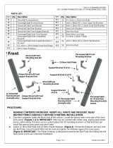
1 Driver / left side bar
1 Passenger / right side bar
1 Driver / left
mounting bracket, front
1 Passenger / right
mounting bracket, front
1 Driver / left
mounting bracket, middle
1 Passenger / right
mounting bracket, middle
1 Driver / left
mounting bracket, rear
1 Passenger / right
mounting bracket, rear
12 Button head cap bolt,
6mm x 25mm
24 Flat washer, 6mm x 22mm
12 Nylock nut, 6mm
2 Hex bolt, 8mm x 35mm
2 Flat washer, 8mm x 25mm
2 Lock washer, 8mm
6 Nut plate, 10mm
6 Hex bolt, 10mm x 35mm
12 Hex bolt, 10mm x 25mm
6 Flat washer, 10mm x 30mm
12 Flat washer, 10mm x 25mm
18 Lock washer, 10mm
Tools Required
Torque wrench Allen wrench
Socket, 10mm Wrench, 10mm
Socket, 13mm Level
Socket, 16mm

ARIESAUTOMOTIVE.COM • NEED ASSISTANCE? • 877.287.8634 • 35700-INS-RB • PAGE 2
1. Start installation on the front passenger-side of the
vehicle. Determine if the vehicle has an open-floor panel
or a threaded hole in the floor panel for the top tab on
the bracket, see figures 1 and 2. Remove any insulation
that may be covering the mounting locations.
2. Locate the front passenger-side bracket.
Note: The mounting brackets are specific to
each mounting location. Ensure you have the
correct bracket identified before proceeding.
Vehicles with open mounting location: Insert one
10mm nut plate into the large square opening in the floor
panel. Line up the threaded nut with the small hole in line
with the tab on the bracket, see figure 1. Bolt the bracket
to the nut plate with one 10mm x 35mm hex bolt, one
10mm lock washer and one 10mm flat washer, see figure
3A. Snug the hardware, but do not fully tighten.
Vehicles with factory threaded hole in floor panel:
Bolt the tab on the bracket to the threaded hole in the
floor panel with one 8mm x 35mm hex bolt, one 8mm
lock washer and one 8mm x 24mm OD flat washer,
see figures 2 and 3A. Snug the hardware, but do not
fully tighten.
3. Line up the mounting plate on the bracket with the two
factory holes in the pinch weld. Bolt the mounting bracket
to the back of the pinch weld using two 6mm x 25mm
button head cap bolts, four 6mm x 22mm flat washers,
(two against pinch weld and two inside against the
bracket) and two 6mm nylock nuts, see figure 3A.
Snug the hardware, but do not fully tighten.
Procedure
Figure 3B - Passenger-side
front mounting bracket
Figure 3C - Passenger-side
middle mounting bracket
Figure 3D - Passenger-side
rear mounting bracket
9 3/8" 10 1/8" 8 3/4"
4. Repeat steps 2 through 4 to install the passenger-side
middle and rear mounting brackets.
5. Place the passenger-side side bar onto the mounting
brackets and secure it using six 10mm x 35mm hex bolts,
six 10mm lock washers and six 10mm flat washers,
see figure 5. Note: Mounting cradles on the brackets
should be inline and pointing toward the rear of the
vehicle for proper installation. Snug the hardware,
but do not fully tighten.
6. Adjust side bar so that it is level and centered,
and tighten all bolts to complete the passenger-side
installation.
7. Repeat this process for the driver-side of vehicle.
8. Congratulations on the installation of your new
ARIES 3" round side bars. With the side bars installed,
periodic inspections should be performed to ensure all
mounting hardware remains tight.
To protect your investment, see the 'Notes and Maintenance'
section on the first page of this instruction manual.

PAGE 3 • 35700-INS-RB • 877.287.8634 • NEED ASSISTANCE? • ARIESAUTOMOTIVE.COM
(2) 6mm Flat Washers (inside)
(2) 6mm Flat Washers (outside)
(Fig 1) Opening in floor frame channel
(passenger side-front pictured)
(2) 6mm x 25mm Button Head Bolts
(2) 6mm Nylon Lock Nuts
Insert 10mm Nut Plate into opening and
line up nut with mounting hole on Bracket
Front
(Fig 2) 8mm threaded hole in floor frame channel
(passenger side-front pictured for example)
10mm Nut Plate
10mm x 35mm Hex Bolt
10mm Lock Washer
10mm Flat Washer
OR
8mm x 35mm Hex Bolt
8mm Lock Washer
8mm x 25mm OD x 3mm
Flat Washer
(Fig 3A) Passenger side Front Mounting Bracket
installation pictured ("mid length" bracket)
(Fig 4) Passenger side Rear Mounting
Bracket installation pictured (short bracket)
10mm Nut Plate
10mm x 35mm Hex Bolt
10mm Lock Washer
10mm Flat Washer
OR
8mm x 35mm Hex Bolt
8mm Lock Washer
8mm x 25mm OD x 3mm
Flat Washer
Rear
(2) 6mm x 25mm Button Head Bolts
(4) 6mm Flat Washers
(2) 6mm Nylon Lock Nuts
(2) 10mm x 25mm Hex Bolts
(2) 10mm Lock Washers
(2) 10mm x 25mm Flat Washers
Fig 5
Front
/
