Page is loading ...

IB(6”,5”,4”)RUNNING BOARD
2014-18 RAM PROMASTER VAN 118” WHEELBASE (FULL SIZE)
Page 1 of 7 3/19/12 Rev1(DP)
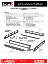
PARTS LIST:
PROCEDURE:
REMOVE CONTENTS FROM BOX. VERIFY ALL PARTS ARE PRESENT. READ
INSTRUCTIONS CAREFULLY BEFORE STARTING INSTALLATION.
1. Start the installation under the driver side of the vehicle. Locate the factory hole in the side of the inner
body panel, (Figures 1 & 3). IMPORTANT: Hole may be covered with rubber plug, sealing tape and/or
heavy undercoating. Remove excess undercoating from all mounting locations so that Brackets will
install flat against body panel and pinch weld.
2. Select (1) 8mm Bolt Plate and (1) 8mm Plastic Retainer, (Figure 2). Thread the Retainer part way onto
the Bolt Plate. Insert the Bolt Plate into the hole and tighten the Retainer against the body panel,
(Figure 3). IMPORTANT: The Plastic Retainer is designed to prevent the Bolt Plate from falling into the
body panel and to aid in Bracket installation.
Item
Qty
Description
Item
Qty
Description
#1
1
Driver/left Running Board
#11
10
8-1.25mm x 25mm Hex Bolts
#2
1
Passenger/right Running Board
#12
5
8mm x 28mm OD x 3mm Large Flat Washers
#3
1
Driver/Left Side Front Bracket
#13
20
8mm x 16mm OD x 1.6mm Small Flat Washers
#4
1
Driver/Left Side Rear Bracket
#14
5
8mm Lock Washers
#5
1
Driver/Left Side Front Support Bracket
#15
5
8mm Hex Nuts
#6
1
Passenger/Right Side Front Bracket
#16
10
8mm Nylon Lock Nuts
#7
2
Passenger/Right Side Center/Rear
Brackets
#17
10
6-1.0mm x 20mm T-Bolts
#8
4
Passenger/Right Side Support Brackets (1-
drv rear)
#18
10
6mm x 18mm OD x 1.6mm Flat Washers
#9
5
8-1.25mm x 35mm Button Head Bolt Plates
#19
10
6mm Hex Nuts
#10
5
8mm Plastic Retainers
Driver/left rear
Mounting Bracket
Front
Passenger/right
#2, #3 and Rear
Mounting Brackets
(same)
Support Bracket
(4 of 4)
Support Bracket (3 of 4)
Passenger/right Front
Mounting Bracket
Support Bracket (2 of 4)
Unique Driver/Left Front
Support Bracket Only
Driver/Left Front
Mounting Bracket
(5) 8mm Bolt Plates
Unique Driver/Left Front
Support Bracket Only
(1) Driver/left
Running Board
(example only)
(1) Passenger/right
Running Board
(example only)

IB(6”,5”,4”)RUNNING BOARD
2014-18 RAM PROMASTER VAN 118” WHEELBASE (FULL SIZE)
Page 2 of 7 3/19/12 Rev1(DP)
3. Select the driver/left front Mounting Bracket. Attach the Bracket to the Bolt Plate with (1) 8mm x 28mm
Large Flat Washer, (1) 8mm Lock Washer and (1) 8mm Hex Nut, (Figure 4). Leave hardware loose at
this time
4. Select the unique driver/left front Support Bracket, (Figure 5). Attach the Support Bracket to the front of
the Mounting Bracket with (1) 8mm x 25mm Hex Bolt, (2) 8mm x 16mm Small Flat Washers and (1)
8mm Nylon Lock Nut, (Figure 6). Line up the top of the Support Bracket with the outside of the pinch
weld. Leave hardware loose at this time.
5. Move to the driver side rear mounting location. Locate the factory hole in the bottom of the floor panel,
(Figure 7). Repeat Steps 1—3 to attach the driver/left rear Bracket to the 8mm Bolt Plate, (Figure 8).
6. Select (1) of the (4) identical Support Brackets, (Figure 9). Attach the Support Bracket to the back of
the rear Mounting Bracket with (1) 8mm x 25mm Hex Bolt, (2) 8mm x 16mm Small Flat Washers and
(1) 8mm Nylon Lock Nut, (Figure 10). Line up the top of the Support Bracket with the outside of the
pinch weld. Leave hardware loose at this time.
7. Place the short driver side Running Board on top of the (2) Brackets. Slip(4)6mm T-bolts into each
bottom channel(Figure 21). Carefully position the Running Board onto the (2) Mounting Brackets.
IMPORTANT: Do not slide, (front to back), the Running Board on the Brackets or damage to the finish
may result. Attach the Running Board to the Mounting Brackets with(2) 6mm T-bolts,(2)6mm flat
washers and (2)6mm lock nuts (Figures 22). Do not tighten at this time。Level and adjust the Running
Board properly and tighten all hardware.
8. Level and adjust the Running Board and tighten the Bracket to Bolt Plate hardware only. Remove the
Running Board. Adjust the Support Brackets as necessary to move the top of the Brackets up to touch
the bend in the pinch weld. Mark the location of the (2) slots in the Support Brackets onto the outside of
the pinch weld, (Figure 11).
9. Use a 5/16” drill bit to drill (2) holes through the pinch weld for the front and rear Support Brackets.
NOTE: Drill the holes as far away from the bottom edge of the pinch weld as possible. IMPORTANT:
Do not drill through the welds in the pinch weld if possible.
10. Attach the top of the Support Brackets to the outside of the pinch weld with (2) 8mm x 25mm Hex Bolts,
(4) 8mm x 16mm Small Flat Washers and (2) 8mm Nylon Lock Nuts, (Figure 12). Reinstall the Running
Board. Level, adjust and tighten all hardware.
11. Move to the passenger side of the vehicle, (Figure 13). Repeat Steps 1—3 to attach the passenger
side front Bracket, (Figures 14 & 15). Repeat Step 6 to attach (1) of the (4) identical Support Brackets.
12. Continue to the center mounting location, (Figure 16). Repeat Steps 5 & 6 to attach the center
Mounting Bracket, (Figure 17).
13. Move along the side of the body to the rear mounting location, (Figure 18). Repeat Steps 5 & 6 to
attach the passenger side rear Mounting Bracket, (Figures 19).
14. Place the long Passenger side Running Board on top of the (3) Brackets. Slip (6)6mm T-bolts into
each bottom channel (Figure 21). Carefully position the Running Board onto the (3) Mounting Brackets.
IMPORTANT: Do not slide, (front to back), the Running Board on the Brackets or damage to the finish
may result. Attach the Running Board to the Mounting Brackets with (2) 6mm T-bolts,(2)6mm flat
washers and (2) 6mm lock nuts (Figures 22). Do not tighten at this time.
15. Level and adjust the Running Board and tighten the Bracket to Bolt Plate hardware only. Remove the
Running Board. Adjust the Support Brackets as necessary to move the top of the Brackets up to touch
the bend in the pinch weld. Mark the location of the slots in the (3) Support Brackets onto the outside of
the pinch weld, (Figure 20).
16. Repeat Steps 9 & 10 to drill and attach the (3) Support Brackets to the pinch weld.
17. Reinstall the Running Board. Level and adjust and tighten all hardware.
18. Do periodic inspections to the installation to make sure that all hardware is secure and tight.
To protect your investment, wax this product after installing. Regular waxing is recommended to add a
protective layer over the finish. Do not use any type of polish or wax that may contain abrasives that could
damage the finish.
IMPORTANT! Any cutting or drilling tool may break or shatter. Government regulations require
safety glasses & equipment at all times when cutting or drilling.

IB(6”,5”,4”)RUNNING BOARD
2014-18 RAM PROMASTER VAN 118” WHEELBASE (FULL SIZE)
Page 3 of 7 3/19/12 Rev1(DP)
For Polished Finishes: Aluminum polish may be used to polish small scratches and scuffs on the finish. Mild
soap may be used also to clean the Running Board.
For black finishes: Mild soap may be used to clean the Running Board.
Driver/left Side Installation Pictured
Front
(Fig 1) Driver side front and rear mounting locations
(Fig 3) Insert Bolt Plate into factory hole
(Fig 2) 8mm Bolt Plate
with Plastic Retainer
(Fig 4) Driver side front Bracket pictured
Front
Front
8mm Large Flat Washer
8mm Lock Washer
8mm Hex Nut
Front
(Fig 5) Unique driver side
front Support Bracket

IB(6”,5”,4”)RUNNING BOARD
2014-18 RAM PROMASTER VAN 118” WHEELBASE (FULL SIZE)
Page 4 of 7 3/19/12 Rev1(DP)
Driver/left Side Installation Pictured
(Fig 6) Driver side front Support Bracket
(Fig 7) Driver side rear mounting location
(Fig 10) Driver side rear Support Bracket
Front
Front
Front
Front
8mm x 25mm Hex Bolt
(2) 8mm Small Flat Washers
8mm Nylon Lock Nuts
8mm Flat Large Washer
8mm Lock Washer
8mm Hex Nut
(Fig 8) Driver side rear Bracket
(Fig 9) Driver side rear
Support Bracket (1 of 4)
8mm x 25mm Hex Bolt
(2) 8mm Small Flat Washers
8mm Nylon Lock Nuts

IB(6”,5”,4”)RUNNING BOARD
2014-18 RAM PROMASTER VAN 118” WHEELBASE (FULL SIZE)
Page 5 of 7 3/19/12 Rev1(DP)
Driver/left Side Installation Pictured
Passenger/right Side Installation Pictured
Fig 11
Front
Front
Level and adjust the Running Board.
Temporarily remove the running board.
Mark and drill 5/16” hole through pinch
weld for each Support Bracket
Fig 12
(Fig 14) Passenger front mounting location
(Fig 13) Passenger side mounting locations
Front
Front
(2) 8mm x 25mm Hex Bolts
(2) 8mm Lock Washers
(2) 8mm Flat Washers
8mm Bolt Plate
Plastic Retainer

IB(6”,5”,4”)RUNNING BOARD
2014-18 RAM PROMASTER VAN 118” WHEELBASE (FULL SIZE)
Page 6 of 7 3/19/12 Rev1(DP)
Passenger/right Side Installation Pictured
(Fig 16) Passenger side #2, #3
and rear mounting locations
(Fig 15) Passenger front Mounting
Bracket and Support Bracket installed
Front
Front
(Fig 17) Passenger side #2 Bracket installed
Front
(Fig 19) Passenger side front installed-
mark to drill through pinch weld
(Fig 18) Passenger side Bracket
layout w-Support Brackets
Front
Front
Front
Bracket
#2, #3 and rear
Brackets (same)

IB(6”,5”,4”)RUNNING BOARD
2014-18 RAM PROMASTER VAN 118” WHEELBASE (FULL SIZE)
Page 7 of 7 3/19/12 Rev1(DP)
Passenger/right Side Installation Pictured
(Fig 21) Slip 6mm T-bolts
into the bottom channel
(Fig 22) Bracket installation
(2)6mmT-bolts
(2)6mm Flat Washers
(2)6mm Hex Nuts
(Fig 20) Passenger side #2 and #3 Brackets
installed-mark to drill through pinch weld
Rear
/