Page is loading ...

Seats and Restraint System
............................. 1-1
Airbag System
........................................... 1-2
Features and Controls
..................................... 2-1
Keys
........................................................ 2-2
Starting and Operating Your Vehicle
............. 2-3
Instrument Panel
............................................. 3-1
Instrument Panel
........................................ 3-2
Warning Lights, Gages, and Indicators
.......... 3-2
Driver Information Center (DIC)
.................... 3-5
Driving Your Vehicle
....................................... 4-1
Your Driving, the Road, and Your Vehicle
..... 4-2
Towing
..................................................... 4-4
Service and Appearance Care
.......................... 5-1
Checking Things Under the Hood
................. 5-2
Tires
........................................................ 5-2
Capacities and Specifications
....................... 5-3
Special Equipment Options
............................ 14-2
SEOs Available with Police Package and
Special Service Package
........................ 14-2
SEOs Standard with Police Package and
Special Service Package
...................... 14-17
Index
................................................................ 1
2008 Chevrolet Tahoe Police and Special
Service Packages
M

GENERAL MOTORS, GM, the GM Emblem,
CHEVROLET, the CHEVROLET Emblem, and the
name TAHOE are registered trademarks of General
Motors Corporation.
The information in this manual supplements the owner
manual. This manual includes the latest information
at the time it was printed. We reserve the right to make
changes after that time without notice.
Keep this manual in the vehicle, so it will be there if it
is needed. If the vehicle is sold, leave this manual in
the vehicle.
The Tahoe Police Package (SEO PPV) has been
designed for police work up to and including high-speed
emergency vehicle operations.
The Tahoe Special Service Package (SEO 5W4) is not
designed nor intended for use in high-speed emergency
vehicle operations.
Canadian Owners
A French language copy of this manual can be obtained
from your dealer/retailer or from:
Helm, Incorporated
P.O. Box 07130
Detroit, MI 48207
1-800-551-4123
www.helminc.com
Propriétaires Canadiens
On peut obtenir un exemplaire de ce guide en français
auprès de concessionnaire ou à l’adresse suivante:
Helm Incorporated
P.O. Box 07130
Detroit, MI 48207
1-800-551-4123
www.helminc.com
Litho in U.S.A.
Part No. 25796689 A First Printing
©
2007 General Motors Corporation. All Rights Reserved.
ii

Airbag System .................................................1-2
Questions and Answers About Airbags and
Specialty Law Enforcement Vehicles ..............1-2
Notices for Customer-Installed Equipment ..........1-5
Airbag Deployment Diagrams ...........................1-6
Section 1 Seats and Restraint System
1-1

Airbag System
Questions and Answers About
Airbags and Specialty Law
Enforcement Vehicles
Q: Can equipment such as radar devices, video
cameras, and radio trees be mounted in a
specialty vehicle equipped with a right front
passenger’s frontal airbag?
A: Yes, but care must be taken to properly mount the
equipment outside of the airbag “deployment zone.”
Q: What is the airbag “deployment zone”?
A: The term “deployment zone” describes the space
an airbag takes up when fully inflated. Airbags
need room to work properly, and anything in the
“deployment zone” — such as improperly mounted
equipment — can greatly affect the performance
of the airbag.
{CAUTION:
Airbags inflate with great force, faster than the
blink of an eye. No objects, such as shotguns,
should be placed over or near the airbag
covers. Equipment mounted too close to an
inflating airbag could break and become a
dangerous projectile in a crash, causing injury
to the vehicle’s occupants. Also, an object too
close to an inflating airbag could prevent the
airbag from operating properly. If this ever
happens, the airbag would not be able to
protect occupants the way it was designed to.
To help prevent injury and to allow the airbag
to perform as it was designed, do not mount
equipment inside the airbag deployment zone.
1-2

Q: How can I identify the airbag “deployment zone”
in my vehicle?
A: See Airbag Deployment Diagrams on page 1-6
for more information. The diagrams provide the
approximate dimensions of the “deployment zones”
for your specialty vehicle. Before doing any
service work, including the installation of any
equipment, consult the appropriate service manual.
Q: Is it possible to shield equipment so it does not
interfere with airbag deployment?
A: While shielding may protect certain equipment from
being damaged or dislodged, it may also negatively
affect how an airbag inflates. Therefore, we cannot
recommend the placement of any equipment in
the deployment zone, even when shielding.
Q: Can the installation of push bumpers on the
front end of the vehicle affect the deployment
of the airbag?
A: Yes, particularly if the push bumper significantly
changes the front structure of the vehicle. However,
GM conducts analysis on various push bumper
configurations to verify effectiveness of the sensing
performance system with minor changes in the
front structure of the vehicle which may occur from
the addition of a push bumper.
1-3

Q: Is there anything I might add to the exterior of
the vehicle that could keep the airbags from
working properly?
A: Yes. If you add things that change your vehicle’s
frame, bumper system, height, front end or side
sheet metal, they may keep the airbag system from
working properly. Also, the airbag system may
not work properly if you relocate any of the airbag
sensors. If you have any questions about this,
you should contact Customer Assistance before
you modify your vehicle. The phone numbers
and addresses for Customer Assistance are in
Step Two of the Customer Satisfaction Procedures
in the owner’s manual. See “Customer Satisfaction
Procedure” in your owner’s manual index.
If your vehicle has rollover roof-rail airbags, see
“Different Size Tires and Wheels” in your owner’s
manual for additional important information.
The service manual has information about the location
of the airbag sensors, sensing and diagnostic module,
and airbag wiring. See “Service Publications Ordering
Information” in your owner’s manual.
1-4

Notices for Customer-Installed
Equipment
Read the following notices before installing equipment
on your specialty vehicle.
Notice: GM-approved service procedures must be
followed to remove and reinstall the instrument
panel to the pad in order to ensure proper airbag
deployment.
Notice: Do not mount equipment on the passenger
side of the instrument panel top pad deployment
zone. Equipment should not be mounted on or
around the passenger airbag opening because of a
deploying airbag. To allow the airbag to perform
as it was designed, do not mount equipment inside
the airbag deployment zone.
Notice: Your police vehicle may have optional
roof-rail airbags. Do not mount a security barrier
such that the ends of the barrier or brackets
are within the roof-rail deployment zones.
Notice: Your police vehicle may have roof-rail
airbags and a rollover sensor. The rollover sensor is
mounted on the centerline of the vehicle between
the driver and right front passenger positions.
If your vehicle has bucket seats, the rollover sensor
will be exposed. Do not mount equipment within
25 mm (1 in) of the rollover sensor. This may impact
the performance of the airbag system. To allow
the airbags to perform as they are designed, do not
mount equipment near this area.
Notice: Avoid installing wiring for roof-rail
emergency lighting or radio antennas that may
restrict the proper deployment of the roof-rail
airbags.
1-5

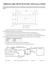
Airbag Deployment Diagrams
A. Passenger Side Instrument Panel Top
Surface Zone
B. Passenger Side Airbag Module Trim
Panel — Rear Edge
Top View of Instrument Panel and Approximate Deployment Area of the Airbag Zone
1-6

C. Passenger Side Door
D. Approximate Dimensions of Inflated Airbag
E. Passenger Side Airbag Deployment Zone
F. Passenger Centerline
G. Inside Rearview Mirror
H. Vehicle Centerline
I. Driver Centerline
J. Driver Side Airbag Deployment Zone
K. Front of Steering Wheel
L. Driver Side Door
M. Shift Selector Arc
See Notices for Customer-Installed Equipment on
page 1-5 for more information.
1-7

A. Top Edge of Windshield
B. Top of Instrument Panel
C. Inflated Airbag — Steering Wheel
D. Centerline of Steering Column at Mid-Tilt
E. Driver Airbag Deployment Zone
F. Front of Steering Wheel
See Notices for Customer-Installed Equipment on
page 1-5 for more information.
Side View of Driver Side Airbag Deployment Zone
1-8

A. Top Edge of Windshield
B. Inside Rearview Mirror
C. Instrument Panel Top Surface Zone
D. Passenger Side Airbag Module Trim
Panel — Rear Edge
E. Inflated Airbag — Horizontal Dimension
(Approximate 15.4 in (390 mm))
F. Inflated Airbag — Vertical Dimension
(Approximate 19.3 in (490 mm))
G. Inflated Airbag — Instrument Panel
H. Passenger Airbag Deployment Zone
See Notices for Customer-Installed Equipment on
page 1-5 for more information.
Side View of Passenger Side Airbag
Deployment Zone
1-9

A. Front of Deployment Zone at Front Upper Corner
of Front Door Pad
B. Windshield Pillar Trim with Grab Handle
C. Visor
D. Deployment Zone
E. Top of Deployment Zone — Along Roof-rail at Edge
of Headliner
Roof-rail Airbag Deployment Zone - Passenger Side shown, Driver Side similar
1-10

F. Back of Deployment Zone — At Rear Top Corner of
Rear Door Pad
G. Rear Quarter Window
H. Top Edge of Interior Quarter Trim
I. Bottom of Airbag Deployment Zone — Parallel to
Outside Bottom Edge of Rear Quarter Glass
J. Dimension at Mirror Patch from Top Edge of
Front Door Pad
K. Top Edge of Front Door Pad
L. Top Edge of Rear Door Pad
M. Bottom Outside Edge of Rear Quarter Window
See Notices for Customer-Installed Equipment on
page 1-5 for more information.
1-11

A. Roof-rail Airbag Deployment Zone
B. Underside of Headliner
C. Edge of Headliner
D. Inner Center Pillar Trim
E. Inner Door Pad
F. Seat Centerline
G. Bottom of Door Windows
H. Front Seat Headrests
See Notices for Customer-Installed Equipment on
page 1-5 for more information.
Roof-rail Airbag Driver and Passenger Deployment Zones - View from Rear Cargo Area
1-12

Keys ...............................................................2-2
Specific Cylinder Unit for Single Key - Random
Code System ..............................................2-2
Starting and Operating Your Vehicle .................2-3
Running the Engine While Parked .....................2-3
Section 2 Features and Controls
2-1

Keys
Specific Cylinder Unit for Single
Key - Random Code System
Tahoe Police Package and Special
Service Package
If your vehicles are equipped with one of these options,
the entire fleet of vehicle locks can be operated with
one key.
• SEO 6E2-Specific Fleet Key Code
• SEO 6E8-Specific Fleet Key Code
Your vehicle will be equipped with a standard production
random key code if one of the optional fleet codes
was not ordered.
For specific key code information, contact your dealer.
Your vehicles will be equipped with a key cylinder in
the ignition lock and the driver’s door only. Remote
keyless entry (RKE) is a standard feature and operates
all other doors and the rear liftgate. Six additional
RKE transmitters may have been ordered with your
vehicle. See your dealer for additional information
regarding availability of more RKE units for your vehicle.
The RKE transmitter for your police vehicle has the
vehicle locator/panic alarm button disabled. The horn
will not sound and the exterior lights will not flash when
the button is pressed.
Remote Keyless Entry Transmitter
Programming - SEO AMF (Tahoe Police
Package and Special Service Package)
Do not operate or program the transmitters in the
vicinity of other vehicles that are in the keyless entry
program mode. This prevents the programming of
the transmitters to the incorrect vehicle.
Up to eight transmitters may be programmed to the
RKE on Police and Special Service Package equipped
vehicles. The first four transmitters are given the
position of #1-#4 in the RKE. Any further transmitters
will also be assigned to position #4.
Verify that the proper transmitters are learned to the
vehicle. Do not learn a transmitter with a remote
start button to a vehicle that does not have remote start.
For the proper procedure to be used for learning
transmitters, see your owner’s manual.
2-2

Starting and Operating
Your Vehicle
Running the Engine While Parked
Tahoe Police Package and Special
Service Package
While parked with the engine idling for an extended
period, turn off the following factory equipment if
emergency lighting and communication equipment are
operating:
• Air Conditioner
• Fan
• Rear Window Defogger
• Factory Audio System
See “Running Your Engine While You’re Parked” in your
owner’s manual Index.
Engine Idle Speed - Alternator Output
(Tahoe Police Package and Special
Service Package)
Normal idle speed for the engine is set for 600 rpm.
To increase alternator output while the transmission
remains in PARK (P) or NEUTRAL (N), and the electrical
load on the alternator is large enough, the engine idle
speed can rise to as high as 800 to 1000 rpm.
2-3

✍ NOTES
2-4

Instrument Panel ..............................................3-2
Exterior Lamps ...............................................3-2
Warning Lights, Gages, and Indicators ..............3-2
Instrument Panel Cluster .................................3-2
Speedometer and Odometer ............................3-5
Driver Information Center (DIC) .........................3-5
Section 3 Instrument Panel
3-1

Instrument Panel
Exterior Lamps
Tahoe Police Package and Special
Service Package
The following exterior lighting features apply to vehicles
first sold in the United States.
Your vehicle is equipped with Daytime Running Lamps
(DRL) and an Automatic Headlamp System (AHS).
The DRL and AHS can be turned to OFF with the
headlamp switch when the transmission is in PARK (P)
and the engine is at idle. If the engine is not turned
off, the DRL and AHS will remain OFF when the
transmission is placed in gear. The vehicle may be
driven with the lamps off for one ignition cycle.
Your vehicle may have been built with SEO 9G8, DRL
AND AHS DISABLE. This feature turns off DRL and
AHS and requires manual control of the exterior lighting.
See your dealer to restore the DRL and AHS to
normal operation.
For vehicles first sold in Canada, the DRL and AHS
can be turned off if the transmission is in PARK (P).
See your owner’s manual for more information.
Special Features
Tahoe Police Package and Special Service
Package
The following standard Tahoe features are disabled in the
Tahoe Police Package and Special Service Package.
• Entry Lighting and Exit Lighting
• Remote Keyless Entry Feedback (Horn Beep) and
(Lamps Flash)
Automatic Door Locking is standard. If you need it
disabled, see your dealer.
Warning Lights, Gages, and
Indicators
Instrument Panel Cluster
Tahoe Police Package and Special
Service Package
The Tahoe Special Service Package instrument panel
cluster is similar to the Tahoe Police Package instrument
panel cluster, except that the maximum speed
displayed is lower and additional indicators may be
present. See “Warning Lights, Gages and Indicators” in
the Index of your owner manual for more information.
3-2
/