Page is loading ...

For Use With PS-5, NPL, or CPS Power Supplies
PS5 intructions( see side two for additional instructions)
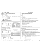
Mechanical Installation Instructions
Remove the two mounting screws from the PS-5 on the terminal strip end.
Replace mounting screws with male-female (m-f) standoffs supplied.
Use two supplied ¼” screws to connect the 1” standoffs to the indicated points on the BP-001. these standoffs are used
for mechanical support only and do not tie to the cabinet
Place the empty BP-001 mounting holes over the m-f standoffs and screw together using two ¼” screws.
Wiring
Connect Battery (+) on the PS-5 to Battery (+) on the BP-001
Connect DC (+) on the PS-5 to PS-5 (+) on the BP-001.
Connect DC (-) on the PS-5 to PS5 (-) on the BP-001.
Connect the System DC Load to the PS-5 (+) and PS-5 (-) terminals of the BP-001
Verify the battery set wires are not connected to the battery
Connect Battery Set (+), red, wire to the BAT (+) terminal of the BP-001
Connect Battery Set (-), black, wire to the BAT (-) terminal of the BP-001
Power-Up
For 24 VDC usage, CUT the BLUE jumper
Power the system and observe the BP-001 System OK LED is OFF after approximately two minutes.
Connect the battery set wires to the battery set.
Observe the BP-001 System OK LED is ON after one minute
Fault Relay
The fault relay provides a failsafe Form ‘C’ contact set. The relay is powered under a normal condition and drops out on
fault. This operation allows for an automatic fault indication to the system in the event of loss of primary AC and a
simultaneous lack of battery power.
Visual Indicators
Yellow L Indicates low charge voltage, can temporarily occur during high charge
Yellow H Indicates high charge voltage
Green OK Indicates system OK
Note: The Yellow L may illuminate if the battery set is only partially charged.
Mechanical Stackup
BATTERY +
BATTERY -
SYSTEM DC +
SYSTEM DC -
BP-001
PS-5
To
Battery Set
To
System Load
H
L
OK
NO
NC
C
Fault Relay
BLUE
Note: Battery (-) on PS-5
board not used with BP-001
7/16" m-f standoff
½" nylon standoff
½" nylon standoff
1" nylon standoff
¼" Screw
BP-001
PS-5
Transformer
BATTERY PRESENCE MONITOR (BP-001)
65A Industrial Way, Wilmington, MA 01887-3499 (978) 658-6717, Fax. (978) 658-8638 www.alarmsaf.com
52-024 05/17/01

For Use With Other AlarmSaf Power Supplys
Power-Up
For 24 VDC useage, CUT the BLUE jumper
Power the system and observe the BP-001 System OK LED
is OFF after two minutes.
Connect the battery set wires to the battery set.
Observe the BP-001 System OK LED is ON after one
minute
Fault Relay
The fault relay provides a failsafe Form ‘C’ contact set. The
relay is powered under a normal condition and drops out
on fault. This operation allows for an automatic fault
indication to the system in the event of loss of primary AC
and a simultaneous lack of battery power.
Visual Indicators
Yellow L Indicates low charge voltage, can
temporarily occur during high charge
Yellow H Indicates high charge voltage
Green OK Indicates system OK
Note: The Yellow LED may illuminate if the battery set is only
partially charged.
Mechanical Installation Instructions
Mount BP-001 board into cabinet with:
A. Four Mounting standoffs
Drill four
1
/
8
” holes in cabinet at mounting location
Install four nylon standoffs with supplied ¼” screws
Mount board to standoffs with four supplied ¼”
screws
B. SnapTrak
Drill two
1
/
8
” holes in cabinet at mounting location
Install Snaptrack
TM
with two ¼” screws and nuts
supplied
Snap board into position such that board is centered in
SnapTrack
TM
TM- Augat Corporation
Wiring
Verify the battery set wires are not connected to the
battery
Connect Battery (+) on the Power Supply to Battery (+) on
the BP-001
Connect DC (+) on the Power Supply to PS-5 (+) on the
BP-001.
Connect DC (-) on the Power Supply to PS5 (-) on the
BP-001.
Connect the System DC Load to the PS-5 (+) and PS-5 (-)
terminals of the BP-001
Connect Battery Set (+), red, wire to the BAT (+) terminal
of the BP-001
Connect Battery Set (-), black, wire to the BAT (-) terminal
of the BP-001
Mechanical Mounting
2"
3.4"
~ 3"
SnapTrack
4.7"
3.25"
BP-001
BATTERY +
BATTERY -
SYSTEM DC +
SYSTEM DC -
BP-001
Power Supply
To
Battery Set
To
System Load
H
L
OK
NO
NC
C
Fault Relay
BLUE
Note: Battery (-) on PS-5
board not used with BP-001
BATTERY PRESENCE MONITOR (BP-001)
65A Industrial Way, Wilmington, MA 01887-3499 (978) 658-6717, Fax. (978) 658-8638 www.alarmsaf.com
52-024 05/17/01
/


