QOLSYS IQ Panel 2/2+ Software Version 2.6.0 Installation guide

Category
Fire protection
Type
Installation guide
The Qolsys IQ Panel 2 & IQ Panel 2+ is a 7” touchscreen built with an Android operating
system, providing full security and smart home functionality in an easy to use interface.
INSTALLATION MANUAL
Qolsys IQ Panel 2/2+
Software Version 2.6.0
INTRODUCTION
ABOUT THIS GUIDE
QOLSYS CONFIDENTIAL AND PROPRIETARY
PAGE OF 2 183
?
QUESTIONS?
Contact us at
This document outlines the basic hardware specifications and software directions to
install and customize the IQ Panel 2 & IQ Panel 2+. Note that the information
presented is not comprehensive, but is specifically dedicated to those menus,
features, and systems accessible solely to those with the proper installation code.
Features accessible to users and installers alike are outlined in the IQ Panel 2 User
Guide. The information contained is confidential and proprietary, and is solely owned
by Qolsys Inc. Any reproduction, modification or distribution without permission is
strictly prohibited.
Power
Supply
Table
Stand
INCLUDED IN BOX
SUPPORT
TABLE OF CONTENTS
PANEL OVERVIEW
5- Exterior Front
6- Exterior Back
7- Interior
INSTALLING THE PANEL
9- Wall Mount Option
10- Table Stand Option
11- Wiring Diagram
12- Powering the Panel
USER INTERFACE
14- Home Screen Overview
15- Message Center
16- Settings Tray
PROGRAMMING
18- Screen Lock
19- Settings
21- Advanced Settings
22- Setup Wizard
26- Installation
28- Installer/Dealer Settings
37- System Logs
38- Siren and Alarms
41- Security and Arming
44- Camera Settings
46- Z-Wave Device List
47- Sound
51- Partitions
52- Local Automation
SECURITY SENSORS
55- Security Sensors
56- Auto Learn Sensor
57- Add Sensor
58- Scan QR Code
59- Partition Name
60- Sensor Type
61- Sensor Groups
77- Sensor Name
79- Chime Type
80- Voice Prompts
81- Source
82- Edit Sensor
83- Delete Sensor
84- Sensor Status
86- Panel Motion Settings
WI-FI DEVICES
88- Wi-Fi Devices
90- Access Point Settings
91- AP Connected Devices
92- IQ Remote Devices
93- 3rd Party Connections
Z-WAVE™ DEVICES
95- Z-Wave Devices
96- Add Device
97- Clear Device
98- Delete Failed Device
99- Remove All Devices
100- View/Edit Associations
101- Z-Wave Settings
103- SmartStart
104- Provisioning List
BLUETOOTH DEVICES
106- Bluetooth Devices
107- Add Device
108- Edit Device
109- Delete Device
110- Remove All Devices
111- Settings
112- Add Speaker
SYSTEM TESTS
114- System Tests
116- Wi-Fi Test
117- Sensor Test
121- Cellular Test
122- Image Sensor Config
123- Z-Wave Test
124- Rediscover Network
125- Neighbor Info
126- Counters
128- Z-Wave Diagnostics
129- Advanced Z-Wave Diag
130- PowerG Test
131- Zigbee Test
132- Panel Glass Break Test
135- Dual Path Test
136- Daughter Cards Test
137- Panel Test
CUSTOMIZATION
139- User Management
140- Dealer Branding
141- Contact Info
142- Load Custom Logo
143- On-Screen Billboard
144- Load Help Videos
145- Connecting to Wi-Fi
146- Weather
147- Photo Frame
150- Load Images from SD Card
MAINTENANCE
152- Upgrade Software
153- Upgrade Software Using Wi-Fi
154- Software Update Via SD Card
155- Automatic Background Check
156- Battery Replacement
TROUBLESHOOTING
158- About
161- Power Down
162- Panel Reboot
163- Hard Reboot
164- Panel Test Troubleshooting
166- Cannot Load Help Videos
LEGAL
168- Important Information
SPECIFICATIONS
177- Specifications
179- Supported S-Line Sensors
180- Supported PowerG Sensors
181- Supported 433 DSC Sensors
182- Supported 433 AT&T Sensors
PANEL
OVERVIEW
Warning: This Product should be installed in accordance with the National Fire Alarm Code, ANSI/NFPA 72, (National Fire Protection Association,
Batterymarch Park,Quincy, MA 02269) and with National Electric Code, ANSI/NFPA 70. Printed information describing proper installation, operation,
testing, maintenance, evacuation planning, and repair service is to be provided with this Product. In Canada the product shall be installed in accordance with
the Standard for the Installation of Residential Fire Warning Systems, CAN/ULC-S540.
Warning: For Canadian installations this Product and all sensors associated with it (collectively, the “System”) should be tested once a week. The test shall be
performed also with primary DC power de-energized. For recommended smoke detectors maintenance instructions refer to user manual associated with
compatible Qolsys model QS5110-P840 smoke detector.
PANEL OVERVIEW
EXTERIOR FRONT
QOLSYS CONFIDENTIAL AND PROPRIETARY
PAGE OF 5 183
Panel Camera
User Interface
Microphones
LED Status Light
Page Indicator
PANEL OVERVIEW
EXTERIOR BACK
Optional locking
screws for table
mount
Mounting holes
single, double or
triple “gang” box
compatible
Micro SD
Card Slot
Speaker
Rear Access Cover
Siren
QOLSYS CONFIDENTIAL AND PROPRIETARY
PAGE OF 6 183
Speaker
Microphone
Microphone
Optional locking
screw for wall mount
RF Antenna
routing hole
For UL1610 applications
this screw shall be used
for tamper protection
against mounting removal
PANEL OVERVIEW
INTERIOR
Panel Battery*
Z-Wave Plus™
Radio
LTE Sim Card
“Tool-less
Terminal Block
Tamper Switch
Cellular Antenna
The battery should NEVER be disconnected without following proper power-down procedures
Failure to comply may result in data corruption, panel failure, and a void of the manufacturer's warranty
*CAUTION
QOLSYS CONFIDENTIAL AND PROPRIETARY
PAGE OF 7 183
Siren
Security
RF Radio
(319.5 MHz, 345 MHz or 433 MHz)
Barrel Jack
Power
PowerG or Image Sensor Antenna
Expansion Slot
PowerG or Image
Sensor Radio
(PowerG Radio is Standard on IQ Panel
2+. PowerG modem is required for
UL1610 compliant installations
Image Sensor Radio is Optional and
not available for use on IQ Panel 2+
with PowerG)
INSTALLING
THE PANEL
!
INSTALLING THE PANEL
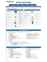
1. Insert your thumb or
finger under the opening on
the back cover and firmly
pull up to remove. This
cover is not needed for wall
mount.
2. Press tabs on the bottom
of the panel and pull apart
to remove the back plate.
Mount to the wall using
appropriate hardware
ensuring it is level.
1. Hang the front of the panel
with the hanging strap on the
back plate as shown above.
2. Using the provided hole in the
lower right hand side of the
backplate as a template, drill a
1/4” hole in the wall and feed the
white RF antenna into the wall.
3. Screw required in break-away
wall tamper for UL 1610
IMPORTANT: Not properly
routing the RF antenna in the
wall will greatly reduce RF sensor
range.
Firmly pinch “diagonally and
down” from the top front of
the bezel at all 4 snap tab
locations to ensure proper
closure. You will hear a “pop
or “snap” sound when each
tab has closed properly and
the gap along the top should
be tightly seated.
IMPORTANT: Not properly
closing the panel could result
in damage to the backplate
or false panel tampers.
WALL MOUNT OPTION
Connect the power supply to
the barrel jack or to the (+/
Red) and (-/Black) terminals if
using a custom length wire.
1. Latch the bottom of the
panel into place, ensuring the
the RF antenna and power
wire are routed into the wall
and not pinched.
2. Swing the panel up towards
the 4 snap tabs at the top.
1
2
1
2
1
2
3
Note: For UL/ULC Commercial Burg installations (UL1610/ULC-
S304 Security Level II compliant) use only wall mount option
This product when installed as per these
instructions does not present the risk of
fire, electric shock, or injury to persons.
INSTALLING THE PANEL
1. With the included power
supply and cable, plug the
barrel connector into the
jack next to the terminals as
shown above.
2. Route the cable under the
hook next to the battery.
3. Route the cable through
the strain relief opening.
Replace the cover by
inserting the top first, then
while making sure the
cable passes under the
opening firmly press down
on the bottom until the
cover “snaps” into place.
QOLSYS CONFIDENTIAL AND PROPRIETARY
PAGE OF 10 183
TABLE STAND OPTION
Insert your thumb or finger
under the opening on the
back cover and firmly pull
up to remove.
1
2
3
Insert table stand dowels
into the 2 upper keyholes.
Slide the stand firmly
upwards until you hear a
click” from each side.
INSTALLING THE PANEL
WIRING DIAGRAM
QOLSYS CONFIDENTIAL AND PROPRIETARY
PAGE OF 11 183
NOTE: Use only UL/ cUL listed external
siren in UL/cUL listed installations.
Rating:12vDC/300mA
NOTE: Inputs are used only for residential
Burglary applications. SENSOR 1, 2 & EXT
SIREN are not permissible in UL1610
installations.
IMPORTANT IF USING CUSTOM LENGTH
WIRE:
- 5.5vDC Transformer: Use 18AWG wire
no longer than 25ft to ensure sufficient
power is received at the panel.
- 7vDC Transformer: Use 18AWG wire no
longer than 100ft to ensure sufficient
power is received at the panel.
* The minimum permissible wire size shall
not be smaller than 22 AWG
** A 7vDC power supply is only supported
on panels with hardware revision E or
newer.
NOTES
5vDC to 7vDC* IN
GND
SENSOR 1
GND
SENSOR 2
GND
EXT SIREN
GND
**WARNING! Use 5vDC to
7vDC** Power Supply ONLY
4.7k EOL
CLOSED LOOP
CIRCUIT
-
+
EXT SIREN:
Maximum Voltage: 12vDC
Maximum Current: 300mA
5vDC to 7vDC** IN
BARREL JACK
BARREL JACK FOR
USE WITH SUPPLIED
BARREL CONNECTOR
CABLE ONLY.
STRIPED WIRE IS
POSITIVE (+)
4.7k EOL
Input rating: 100-240vAC, 50/60Hz, 0.2A
Output rating: 5.0 - 7.0vDC, 1.0A
Model SW-055100A or SW-050100A or
SW-070100AB
INSTALLING THE PANEL
QOLSYS CONFIDENTIAL AND PROPRIETARY
PAGE OF 12 183
Press and hold the power button on
the right side of the panel for 3
seconds to power up.
POWERING THE PANEL
Connect power supply.
WARNING! Use a 5vDC to 7vDC Power Supply ONLY
If using the provided cable, the “striped” wire is (+)
Note: Power supply shall be located within same room as control unit
USER
INTERFACE
USER INTERFACE
Header &
Settings Tray
Primary User
Interface &
Partition
The home screen is divided into three sections. The header shows the date & time, todays weather, message center and
the Settings tray. The Primary interface shows arming options and sensor status & partition select. The footer shows panic
options and additional pages.
QOLSYS CONFIDENTIAL AND PROPRIETARY
PAGE OF 14 183
Page
Indication and
Emergency
HOME SCREEN OVERVIEW
The header contains the the pull down settings tray, the weather icon, time/date and a message icon in the
upper right portion of the screen where you will find Security Provider messages and contact info, alerts,
video tutorials and FAQ’s
USER INTERFACE
QOLSYS CONFIDENTIAL AND PROPRIETARY
PAGE OF 15 183
This is where you will find the Security Provider’s Contact Information
This is where you will find Video Tutorials to help with common questions
This is where you will find Panel Alerts/Alarms notifications
MESSAGE CENTER
This is where you will find messages from the Security Provider
USER INTERFACE
SETTINGS TRAY
QOLSYS CONFIDENTIAL AND PROPRIETARY
PAGE OF 16 183
To access the Settings tray swipe down on the bar at the top of the screen. The
Settings tray has quick access to system, battery, Wi-Fi, bluetooth & cellular status as
well as volume control, brightness, a lock screen icon and other quick settings.
Swipe down
for access
FIND IT
When partitions are
DISABLED, a Status
icon resides in the
upper left corner of
the settings tray.
Touch this icon to
return to the security
page.
When partitions or
screen lock are
ENABLED, a Lock
Screen icon replaces
the Status icon.
Touch this icon to
switch between
partitions.
PROGRAMMING
When the “Screen Lock” or “Partitions” setting are enabled, a lock screen will be presented once the panel has been woken
from either a touch on the screen or pressing the wake/sleep button on the side of the panel. This prevents unauthorized
access to the panel and/or one partition from accessing another as well as managing permissions to “Advanced Settings.
PROGRAMMING
SCREEN LOCK
4 DIGIT SCREEN LOCK
6 DIGIT SCREEN LOCK
QOLSYS CONFIDENTIAL AND PROPRIETARY
PAGE OF 18 183
The Settings page allows quick access to various simple
features & settings that do not require the protection of a
Dealer, Installer or Master code to be changed.
PROGRAMMING
FIND IT
Swipe down
for access
SETTINGS
SETTINGS
Setting
Description
Display
Adjust brightness, font size & 12/24 hour time
SD Card
Mount, unmount and manage SD Cards that are installed in a panel
Weather Temperature
Toggle between Farenheight and Celcius
Status
View the "Current Status" of security sensors: Zone #, Name, Status
(Open, Close, Active, Idle, Tamper, Failure), Battery and sensor History. Also
view “Alarms” and “History” for security sensors globally
Z-Wave™ Device Status
View the "Current Status" of Z-Wave devices: Name, Type, Status (Normal,
Failure), and Battery. Also view “Alerts” and “History” for Z-Wave globally
Other Z-Wave Devices
Shows Z-Wave devices that are learned into the panel but that are not part
of the main user interface (Lights, Locks, Thermostats & Garage Doors)
PROGRAMMING
SETTINGS
Setting
Description
EU Events
Display events as required for EN Grade 2. NOTE: This icon will only appear when the “En Grade 2" setting is Enabled.
Automation
Add, Edit or mange local lighting automation rules. These rules are separate from any cloud based rules
that may be set through Alarm.com. Examples of possible rules are as follows:
-
Night: Turns light on at 7pm and off at 6am
-
Evening: Turns light on at 7pm and off at 11pm
-
Front Door: Turns light on for 15mins when Front Door opens between 5pm and 7am (must have a
sensor with the default quick name “Front Door” added in the panel)
-
Doorbell: Turns light on between 5pm and 7am for 15 mins when Doorbell is activated (must have a
sensor with the default quick name “Doorbell” added in the panel)
Activity Monitor
Activity Monitor allows access to disarm sensors that are programmed as 24 hours zones, such as Sensor
Groups 8, 9 & 25. A valid Master, User or Guest code is required to control 24 hour activity sensors. 2
options are provided:
-
Quick Access: 300 second temporary access
-
Deactivate: Disarms 24 hour sensors until they are re-activated manually
License
Qolsys End User License Agreement
Advanced Settings
Access advanced settings & programming. A valid Dealer (default 2222), Installer (default 1111) or Master
Code (default 1234) is required
Smart Energy Optimizer
Shift energy usage to off-peak hours (thermostats) and reduce energy usage during on-peak hours
  • Page 1 1
  • Page 2 2
  • Page 3 3
  • Page 4 4
  • Page 5 5
  • Page 6 6
  • Page 7 7
  • Page 8 8
  • Page 9 9
  • Page 10 10
  • Page 11 11
  • Page 12 12
  • Page 13 13
  • Page 14 14
  • Page 15 15
  • Page 16 16
  • Page 17 17
  • Page 18 18
  • Page 19 19
  • Page 20 20
  • Page 21 21
  • Page 22 22
  • Page 23 23
  • Page 24 24
  • Page 25 25
  • Page 26 26
  • Page 27 27
  • Page 28 28
  • Page 29 29
  • Page 30 30
  • Page 31 31
  • Page 32 32
  • Page 33 33
  • Page 34 34
  • Page 35 35
  • Page 36 36
  • Page 37 37
  • Page 38 38
  • Page 39 39
  • Page 40 40
  • Page 41 41
  • Page 42 42
  • Page 43 43
  • Page 44 44
  • Page 45 45
  • Page 46 46
  • Page 47 47
  • Page 48 48
  • Page 49 49
  • Page 50 50
  • Page 51 51
  • Page 52 52
  • Page 53 53
  • Page 54 54
  • Page 55 55
  • Page 56 56
  • Page 57 57
  • Page 58 58
  • Page 59 59
  • Page 60 60
  • Page 61 61
  • Page 62 62
  • Page 63 63
  • Page 64 64
  • Page 65 65
  • Page 66 66
  • Page 67 67
  • Page 68 68
  • Page 69 69
  • Page 70 70
  • Page 71 71
  • Page 72 72
  • Page 73 73
  • Page 74 74
  • Page 75 75
  • Page 76 76
  • Page 77 77
  • Page 78 78
  • Page 79 79
  • Page 80 80
  • Page 81 81
  • Page 82 82
  • Page 83 83
  • Page 84 84
  • Page 85 85
  • Page 86 86
  • Page 87 87
  • Page 88 88
  • Page 89 89
  • Page 90 90
  • Page 91 91
  • Page 92 92
  • Page 93 93
  • Page 94 94
  • Page 95 95
  • Page 96 96
  • Page 97 97
  • Page 98 98
  • Page 99 99
  • Page 100 100
  • Page 101 101
  • Page 102 102
  • Page 103 103
  • Page 104 104
  • Page 105 105
  • Page 106 106
  • Page 107 107
  • Page 108 108
  • Page 109 109
  • Page 110 110
  • Page 111 111
  • Page 112 112
  • Page 113 113
  • Page 114 114
  • Page 115 115
  • Page 116 116
  • Page 117 117
  • Page 118 118
  • Page 119 119
  • Page 120 120
  • Page 121 121
  • Page 122 122
  • Page 123 123
  • Page 124 124
  • Page 125 125
  • Page 126 126
  • Page 127 127
  • Page 128 128
  • Page 129 129
  • Page 130 130
  • Page 131 131
  • Page 132 132
  • Page 133 133
  • Page 134 134
  • Page 135 135
  • Page 136 136
  • Page 137 137
  • Page 138 138
  • Page 139 139
  • Page 140 140
  • Page 141 141
  • Page 142 142
  • Page 143 143
  • Page 144 144
  • Page 145 145
  • Page 146 146
  • Page 147 147
  • Page 148 148
  • Page 149 149
  • Page 150 150
  • Page 151 151
  • Page 152 152
  • Page 153 153
  • Page 154 154
  • Page 155 155
  • Page 156 156
  • Page 157 157
  • Page 158 158
  • Page 159 159
  • Page 160 160
  • Page 161 161
  • Page 162 162
  • Page 163 163
  • Page 164 164
  • Page 165 165
  • Page 166 166
  • Page 167 167
  • Page 168 168
  • Page 169 169
  • Page 170 170
  • Page 171 171
  • Page 172 172
  • Page 173 173
  • Page 174 174
  • Page 175 175
  • Page 176 176
  • Page 177 177
  • Page 178 178
  • Page 179 179
  • Page 180 180
  • Page 181 181
  • Page 182 182
  • Page 183 183

QOLSYS IQ Panel 2/2+ Software Version 2.6.0 Installation guide

Category
Fire protection
Type
Installation guide

Ask a question and I''ll find the answer in the document

Finding information in a document is now easier with AI