Omron CX-Process Tool 5.2 User manual
- Category
- Software
- Type
- User manual
This manual is also suitable for

Cat. No. W372-E1-14
CX-Process Tool Ver. 5.2
SYSMAC CS/CJ Series
WS02-LCTC1-EV5
OPERATION MANUAL


WS02-LCTC1-EV5
CX-Process Tool Ver. 5.2
Operation Manual
Revised October 2010

iv

!
!
!
v
Notice:
OMRON products are manufactured for use according to proper procedures by a qualified operator
and only for the purposes described in this manual.
The following conventions are used to indicate and classify precautions in this manual. Always heed
the information provided with them. Failure to heed precautions can result in injury to people or dam-
age to property.
DANGER Indicates an imminently hazardous situation which, if not avoided, will result in death or
serious injury. Additionally, there may be severe property damage.
WARNING Indicates a potentially hazardous situation which, if not avoided, could result in death or
serious injury. Additionally, there may be severe property damage.
Caution Indicates a potentially hazardous situation which, if not avoided, may result in minor or
moderate injury, or property damage.
OMRON Product References
All OMRON products are capitalized in this manual. The word “Unit” is also capitalized when it refers
to an OMRON product, regardless of whether or not it appears in the proper name of the product.
The abbreviation “Ch,” which appears in some displays and on some OMRON products, often means
“word” and is abbreviated “Wd” in documentation in this sense.
The abbreviation “PLC” means Programmable Controller. “PC” is used, however, in some Program-
ming Device displays to mean Programmable Controller.
Visual Aids
The following headings appear in the left column of the manual to help you locate different types of
information.
Note Indicates information of particular interest for efficient and convenient operation
of the product.
1, 2, 3... 1. Indicates lists of one sort or another, such as procedures, checklists, etc.
Copyrights and Trademarks
Windows is a registered trademark of the Microsoft Corporation.
Other system and product names that appear in this manual are the trademarks or registered trade-
marks of the respective company.
OMRON, 2000
All rights reserved. No part of this publication may be reproduced, stored in a retrieval system, or transmitted, in any
form, or by any means, mechanical, electronic, photocopying, recording, or otherwise, without the prior written permis-
sion of OMRON.
No patent liability is assumed with respect to the use of the information contained herein. Moreover, because OMRON is
constantly striving to improve its high-quality products, the information contained in this manual is subject to change
without notice. Every precaution has been taken in the preparation of this manual. Nevertheless, OMRON assumes no
responsibility for errors or omissions. Neither is any liability assumed for damages resulting from the use of the informa-
tion contained in this publication.

vi
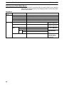
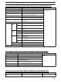
About Loop Controllers
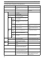
Loop Control Types, Functional Elements, and Versions
Loop Controller Types
There are two types of CS/CJ-series Loop Controller: Separate Loop Control-
lers and Loop Controllers Pre-installed in CPU Units
Loop
Controller
type
Type name Product name Model PLC series and Unit type
Separate Separate
Loop
C
Loop Control Unit CS1W-LC001 CS-series CPU Bus Unit Loop
Controller
oop
Controller Loop Control
Board
CS1W-LCB01/05 CS-series Inner Board Loop Controller
Loop Control
Board with
Gradient
Temperature
Controller
CS1W-LCB05-GTC CS-series Inner Board Loop Controller
Pre-installed in
CPU Unit
CPU Unit with
Pre-installed
Loop
Ctll
Process-control
CPU Unit
CS1D-CPUPA one-Unit Loop Controller consisting
of an Inner Board pre-installed in a
CS-series CS1D-H CPU Unit
p
Controller Loop-control CPU
Unit
CJ1G-CPUPAn Inner Board Loop Controller
integrated into a CS-series CJ1-H CPU
Unit
Loop-control CPU
Unit with Gradient
Temperature
Controller
CJ1G-CPUP-GTC An Inner Board Loop Controller
integrated into a CJ-series CJ1-H CPU
Unit
Loop Controller Functional Elements
•Separate Loop Controllers consist of only the Loop Controller functional ele-
ment (i.e., the Loop Controller element).
•CPU Units with Pre-installed Loop Controller consists of a CPU Unit functional
element (i.e., the CPU Unit element) and the Loop Controller functional ele-
ment (i.e., the Loop Controller element).
Versions
The functional elements (i.e., the CPU Unit element and Loop Controller ele-
ment) have versions.
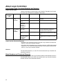
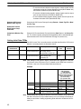
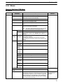
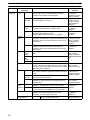
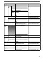
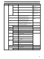
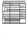
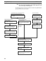
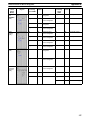
Model Numbers and Functional Elements
The following table lists the Loop Controller product model numbers, the func-
tional element names for the CPU Unit elements and Loop Controller elements,
and the versions of the functional elements.

vii
Product Product model
b
Unit version
f h
Configuration
name number of the
product
CPU unit element Loop Controller element
pro
d
uc
t
model
(See note.)
CPU Unit
model with
same
functionality
Functional
element unit
version
Functional
element
name
Functional
element
Loop Control
Unit
CS1W-LC001 Pre-Ver. 2.0 --- LC001 Ver. 2.5
Loop Control
Bd
CS1W-LCB01 Ver. 2.0 or
l
--- LCB01 Ver. 2.0 or later
p
Board CS1W-LCB05 later LCB05 Ver. 2.0 or later
Loop Control
Board with
Gradient
Temperature
Controller
CS1W-LCB05-
GTC
Ver. 3.0 or
later
--- LCB05-GTC Ver. 3.0 or later
Process-
control CPU
CS1D-CPU65P --- CS1D-CPU65H Ver. 1.0 or later LCB05D Ver. 1.0
con
t
ro
l CPU
Unit CS1D-CPU67P CS1D-CPU67H Ver. 1.0 or later LCB05D Ver. 1.0
Loop-control
CPU U i
CJ1G-CPU42P --- CJ1G-CPU42H Ver. 3.0 or later LCB01 Ver. 2.0 or later
p
CPU Unit CJ1G-CPU43P CJ1G-CPU43H Ver. 3.0 or later LCB03 Ver. 2.0 or later
CJ1G-CPU44P CJ1G-CPU44H Ver. 3.0 or later LCB03 Ver. 2.0 or later
CJ1G-CPU45P CJ1G-CPU45H Ver. 3.0 or later LCB03 Ver. 2.0 or later
Loop-control
CPU Unit with
Gradient
Temperature
Controller
CJ1G-CPU45P-
GTC
Ver. 3.0 or
later
CJ1G-CPU45H Ver. 3.0 or later LCB05-GTC Ver. 3.0 or later
Note Only Separate Loop Controllers have a unit version for the product model. CPU
Units with Pre-installed Loop Controllers do not have a unit version for the prod-
uct model.
Notation in this Manual
This manual uses the following notation.
•“Loop Controller” is used as a generic term to refer to the Loop Controllers in
general.
•“LCB” is used to refer to specific Loop Controller functional elements. For
example, the Loop Controller function element in a CS1W-LCB05 Loop Con-
trol Board is the LCB05, so “LCB05” is used to refer to the Loop Controller func-
tional element. The Loop Controller function element in a CJ1G-CPU44P
Loop-control CPU Unit is the LCB03, so “LCB03” is used to refer to the Loop
Controller functional element.
•Model numbers are used to refer to specific Loop Controller models.
In the CX-Process Tool Operation Manual for version 3.2 or earlier, functional
element names (LCB) are given as “Loop Control Board.” In the CX-Process
Tool Operation Manual for version 4.0 or higher, simply “LCB” is used.

viii
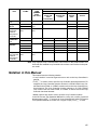
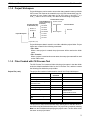
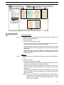
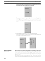
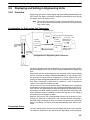
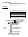
Unit Version Notation on Products
Loop Control Boards
A “unit version” has been introduced to manage CPU Units, Special I/O Units,
and Inner Boards in the CS/CJ Series according to differences in functionality
accompanying upgrades. This system applies to Units manufactured since Oc-
tober 1, 2003. The unit version code is provided on the nameplate of the product
for which unit versions are being managed, as shown below for the Loop Control
Board.
Product nameplate
Unit version
Example for unit version 1.5
Loop Control Board
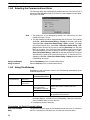
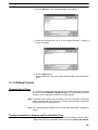
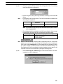
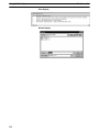
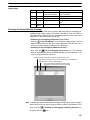
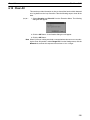
The CX-Process Tool can be used to confirm the unit versions of Loop Control
Boards in the Monitor Run Status Window. After connecting the CX-Process
Tool online, select Operation – Monitor Run Status from the Execute Menu.
Confirm the unit version in ITEM099 (MPU/FROM version display) under from
the System Common Block (Block Model 000) in the Monitor Run Status Win-
dow.
ITEM Data name Data
099 MPU/FROM version indication V1.50
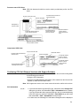
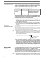
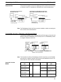
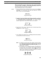
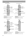
Functional Element Name and Version Code for Process-control CPU Units and
Loop-control CPU Units
The functional element name and functional element version code for Process-
control CPU Units and Loop-control CPU Units are provided on the nameplate
as shown in the following diagrams.
Version V1.50 and onwards must be indicated.

ix
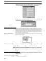
Process-control CPU Units
Note CPU Unit elements for which no version code is provided are pre-Ver. 2.0 CPU
Units.
Process-control CPU Unit
Product nameplate
Functional element name for
CPU Unit element
Nameplate on
left side of Unit
Functional element name for
Loop Controller element
Functional element version code for
Loop Controller element
Functional element
version code for the
CPU Unit element
Functional element
version code for
Loop Controller ele-
ment
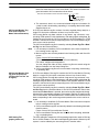
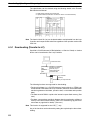
Loop-control CPU Units
Loop-control CPU Unit Unit model number
Product nameplate
Lot No.
Functional element
version code for
CPU unit element
Product model and functional
element name
Recommended location for
attaching version label
Functional element
version code for
Loop Controller
element
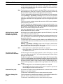
Confirming CPU Unit Element Versions with Support Software
CX-Programmer version 4.0 can be used to confirm the unit version using either
of the following two methods.
•Using the PLC Information
•Using the Unit Manufacturing Information (This method can also be used for
Special I/O Units and CPU Bus Units.)
Note CX-Programmer version 3.3 or lower cannot be used to confirm unit versions.
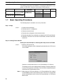
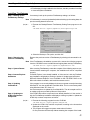
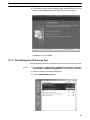
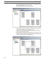
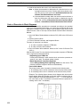
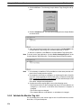
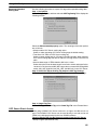
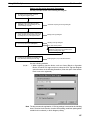
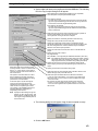
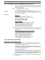
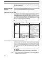
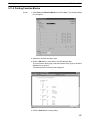
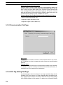
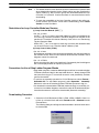
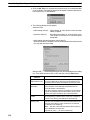
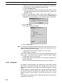
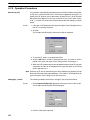
PLC Information
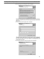
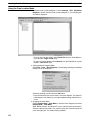
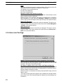
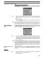
1, 2, 3... 1. If you know the device type and CPU type, select them in the Change PLC
dialog box, go online, and select PLC – Edit – Information from the menus.
If you do not know the device type and CPU type, but are connected directly
to the CPU Unit on a serial line, select PLC – Auto Online to go online, and
then select PLC – Edit – Information from the menus.
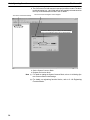
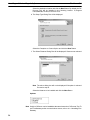
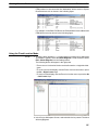
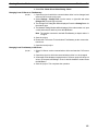
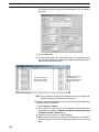
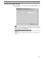
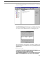
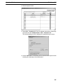
2. In either case, the following PLC Information Dialog Box will be displayed.

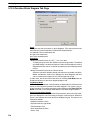
x
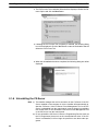
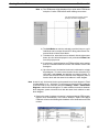
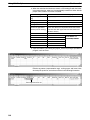
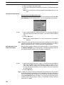
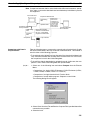
Functional element name
for CPU Unit element
Functional element version
code for CPU Unit element
Use the above display to confirm the unit version of the CPU Unit that is con-
nected online.
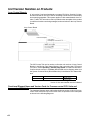
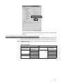
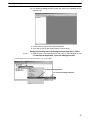
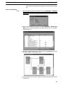
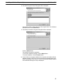
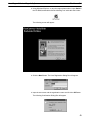
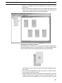
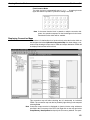
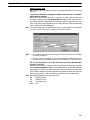
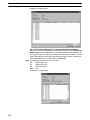
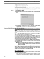
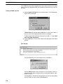
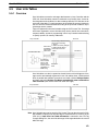
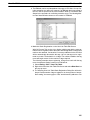
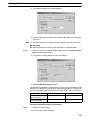
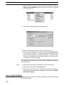
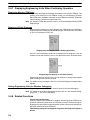
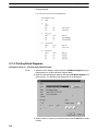
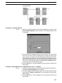
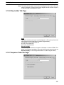
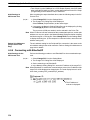
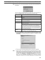
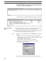
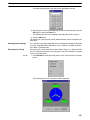
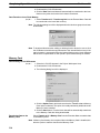
Unit Manufacturing Information
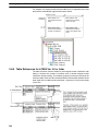
1, 2, 3... 1. In the I/O Table Window, right-click and select Unit Manufacturing In-
formation – CPU Unit.
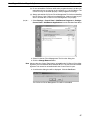
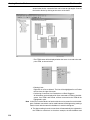
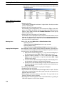
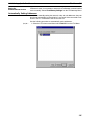
2. The following Unit Manufacturing Information Dialog Box will be displayed.

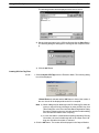
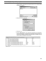
xi
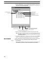
Functional element version
code for CPU Unit element
Use the above display to confirm the unit version of the CPU Unit connected
online.
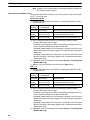
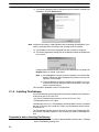
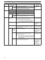
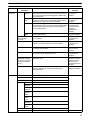
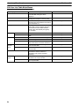
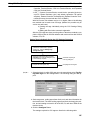
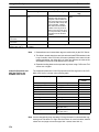
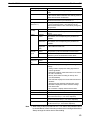
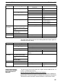
Functional Element Versions and Programming Devices
The Programming Device that supports the functional element version code
must be used to enable all the functions in the corresponding functional element.
Note Upgrading versions is not necessary if only the basic functions of the CPU Unit
element are required.
CPU Unit Element
Loop Controller Programming Device
Functional
element name
Functional
element version
CX-Process Tool CX-Programmer
(See note.)
CS1G/H-CPUHPre-Ver. 2.0 --- ---
/
Ver. 2.0 Ver. 4.0 or higher
Ver. 3.0 Ver. 5.0 or higher
CS1D-CPUHVer. 1.1 Ver. 4.0 or higher
CJ1G-CPUHVer. 3.0 Ver. 5.0 or higher
Ver. 4.0 Ver. 7.0 or higher

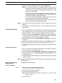
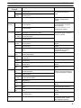
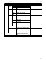
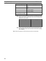
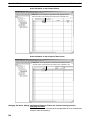
xii
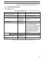
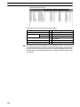
Loop Controller Element
Loop Controller Programming Device
Functional
element name
Functional
element version
CX-Process Tool CX-Programmer
(See note.)
LCB01 Ver. 1.0 Ver. 3.0 or higher ---
Ver. 1.5 Ver. 3.2 or higher
Ver. 2.0 Ver. 4.0 or higher
Ver. 3.0 Ver. 5.0 or higher
Ver. 3.5 Ver. 5.2 or higher
Ver. 3.6 Ver. 5.23 or higher
LCB05 Ver. 1.0 Ver. 3.0 or higher
Ver. 1.5 Ver. 3.2 or higher
Ver. 2.0 Ver. 4.0 or higher
Ver. 3.0 Ver. 5.0 or higher
Ver. 3.5 Ver. 5.2 or higher
Ver. 3.6 Ver. 5.23 or higher
LCB05-GTC Ver. 3.0 Ver. 5.1 or higher
LCB03 Ver. 2.0 Ver. 4.0 or higher
Ver. 3.0 Ver. 5.0 or higher
Ver. 3.5 Ver. 5.2 or higher
Ver. 3.6 Ver. 5.23 or higher
LCB03-GTC Ver. 3.0 Ver. 5.1 or higher
LCB05D Ver. 1.0 Ver. 3.1 or higher

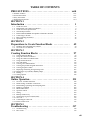
TABLE OF CONTENTS
xiii
PRECAUTIONS xxiii. . . . . . . . . . . . . . . . . . . . . . . . . . . . . . . . .
1 Intended Audience xxiv. . . . . . . . . . . . . . . . . . . . . . . . . . . . . . . . . . . . . . . . . . . . . . . . . . . . . . . . . . .
2 General Precautions xxiv. . . . . . . . . . . . . . . . . . . . . . . . . . . . . . . . . . . . . . . . . . . . . . . . . . . . . . . . . .
3 Safety Precautions xxiv. . . . . . . . . . . . . . . . . . . . . . . . . . . . . . . . . . . . . . . . . . . . . . . . . . . . . . . . . . .
4 Application Precautions xxvi. . . . . . . . . . . . . . . . . . . . . . . . . . . . . . . . . . . . . . . . . . . . . . . . . . . . . .
SECTION 1
Introduction 1. . . . . . . . . . . . . . . . . . . . . . . . . . . . . . . . . . . .
1-1 CX-Process Tool 2. . . . . . . . . . . . . . . . . . . . . . . . . . . . . . . . . . . . . . . . . . . . . . . . . . . . . . . . .
1-2 Relationship with CX-Process Monitor 9. . . . . . . . . . . . . . . . . . . . . . . . . . . . . . . . . . . . . . .
1-3 CX-Process Tool Specifications 13. . . . . . . . . . . . . . . . . . . . . . . . . . . . . . . . . . . . . . . . . . . . .
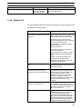
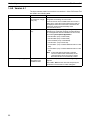
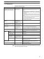
1-4 Version Improvements 15. . . . . . . . . . . . . . . . . . . . . . . . . . . . . . . . . . . . . . . . . . . . . . . . . . . .
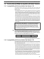
1-5 Function Blocks/ITEMs Incompatible with Earlier Versions 25. . . . . . . . . . . . . . . . . . . . . .
1-6 Connecting to the PLC 31. . . . . . . . . . . . . . . . . . . . . . . . . . . . . . . . . . . . . . . . . . . . . . . . . . . .
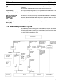
1-7 Basic Operating Procedures 36. . . . . . . . . . . . . . . . . . . . . . . . . . . . . . . . . . . . . . . . . . . . . . . .
1-8 Operations 44. . . . . . . . . . . . . . . . . . . . . . . . . . . . . . . . . . . . . . . . . . . . . . . . . . . . . . . . . . . . .
SECTION 2
Preparations to Create Function Blocks 49. . . . . . . . . . . . .
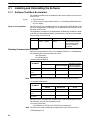
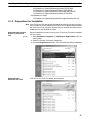
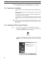
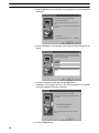
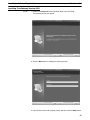
2-1 Installing and Uninstalling the Software 50. . . . . . . . . . . . . . . . . . . . . . . . . . . . . . . . . . . . . .
2-2 Overview of User Interface 69. . . . . . . . . . . . . . . . . . . . . . . . . . . . . . . . . . . . . . . . . . . . . . . .
SECTION 3
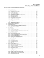
Creating Function Blocks 97. . . . . . . . . . . . . . . . . . . . . . . . .
3-1 Creating Function Block 99. . . . . . . . . . . . . . . . . . . . . . . . . . . . . . . . . . . . . . . . . . . . . . . . . .
3-2 Using the CX-Process Monitor 132. . . . . . . . . . . . . . . . . . . . . . . . . . . . . . . . . . . . . . . . . . . . .
3-3 Using the CX-Process Monitor Plus 138. . . . . . . . . . . . . . . . . . . . . . . . . . . . . . . . . . . . . . . . .
3-4 Using SCADA Software 141. . . . . . . . . . . . . . . . . . . . . . . . . . . . . . . . . . . . . . . . . . . . . . . . . . .
3-5 User Link Tables 159. . . . . . . . . . . . . . . . . . . . . . . . . . . . . . . . . . . . . . . . . . . . . . . . . . . . . . . .
3-6 Creating User-defined Blocks 173. . . . . . . . . . . . . . . . . . . . . . . . . . . . . . . . . . . . . . . . . . . . . .
3-7 Creating Step Ladder Program Instructions 180. . . . . . . . . . . . . . . . . . . . . . . . . . . . . . . . . . . .
3-8 Creating Sequence Tables 195. . . . . . . . . . . . . . . . . . . . . . . . . . . . . . . . . . . . . . . . . . . . . . . . .
3-9 Displaying and Setting in Engineering Units 207. . . . . . . . . . . . . . . . . . . . . . . . . . . . . . . . . .
3-10 Displaying Loop Controller Memory Maps 212. . . . . . . . . . . . . . . . . . . . . . . . . . . . . . . . . . . .
3-11 Printing 216. . . . . . . . . . . . . . . . . . . . . . . . . . . . . . . . . . . . . . . . . . . . . . . . . . . . . . . . . . . . . . . .
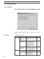
3-12 Setting Options 224. . . . . . . . . . . . . . . . . . . . . . . . . . . . . . . . . . . . . . . . . . . . . . . . . . . . . . . . . .
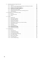
SECTION 4
Online Operation 235. . . . . . . . . . . . . . . . . . . . . . . . . . . . . . . .
4-1 Overview of Online Functions 236. . . . . . . . . . . . . . . . . . . . . . . . . . . . . . . . . . . . . . . . . . . . . .
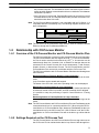
4-2 Initial Settings for Online Connections 238. . . . . . . . . . . . . . . . . . . . . . . . . . . . . . . . . . . . . . .
4-3 Downloading, Uploading and Comparing Data 251. . . . . . . . . . . . . . . . . . . . . . . . . . . . . . . . .
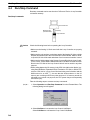
4-4 Run/Stop Command 264. . . . . . . . . . . . . . . . . . . . . . . . . . . . . . . . . . . . . . . . . . . . . . . . . . . . . .
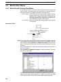
4-5 Monitor Run Status 266. . . . . . . . . . . . . . . . . . . . . . . . . . . . . . . . . . . . . . . . . . . . . . . . . . . . . .
4-6 Operation Check 270. . . . . . . . . . . . . . . . . . . . . . . . . . . . . . . . . . . . . . . . . . . . . . . . . . . . . . . . .
4-7 Tuning 294. . . . . . . . . . . . . . . . . . . . . . . . . . . . . . . . . . . . . . . . . . . . . . . . . . . . . . . . . . . . . . . . .
4-8 Backup and Recovery 306. . . . . . . . . . . . . . . . . . . . . . . . . . . . . . . . . . . . . . . . . . . . . . . . . . . .
4-9 Transferring Tag and Comment Data 309. . . . . . . . . . . . . . . . . . . . . . . . . . . . . . . . . . . . . . . . .
4-10 Clear All 313. . . . . . . . . . . . . . . . . . . . . . . . . . . . . . . . . . . . . . . . . . . . . . . . . . . . . . . . . . . . . . .
4-11 Controlling the CPU Unit 314. . . . . . . . . . . . . . . . . . . . . . . . . . . . . . . . . . . . . . . . . . . . . . . . . .
4-12 Password Protection 315. . . . . . . . . . . . . . . . . . . . . . . . . . . . . . . . . . . . . . . . . . . . . . . . . . . . . .
SECTION 5
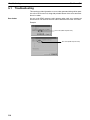
Troubleshooting 317. . . . . . . . . . . . . . . . . . . . . . . . . . . . . . . . .
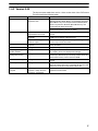
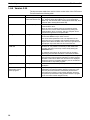
5-1 Troubleshooting 318. . . . . . . . . . . . . . . . . . . . . . . . . . . . . . . . . . . . . . . . . . . . . . . . . . . . . . . . .
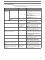
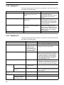
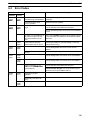
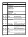
5-2 Error Codes 319. . . . . . . . . . . . . . . . . . . . . . . . . . . . . . . . . . . . . . . . . . . . . . . . . . . . . . . . . . . . .

TABLE OF CONTENTS
xiv
Appendices
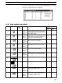
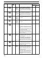
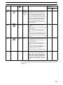
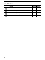
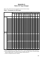
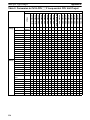
A Table of LC Type Changes 323. . . . . . . . . . . . . . . . . . . . . . . . . . . . . . . . . . . . . . . . . . . . . . . . . . .
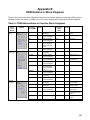
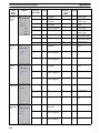
B ITEM Notation in Block Diagrams 325. . . . . . . . . . . . . . . . . . . . . . . . . . . . . . . . . . . . . . . . . . . .
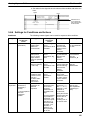
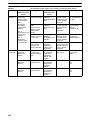
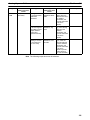
C Setting Segment Programs 329. . . . . . . . . . . . . . . . . . . . . . . . . . . . . . . . . . . . . . . . . . . . . . . . . . .
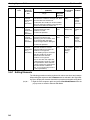
D Sequence Table Design Sheet 337. . . . . . . . . . . . . . . . . . . . . . . . . . . . . . . . . . . . . . . . . . . . . . . . .
Revision History 339. . . . . . . . . . . . . . . . . . . . . . . . . . . . . . . . .

xv
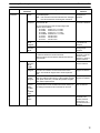
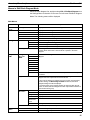
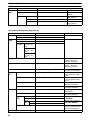
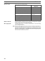
About this Manual:
This manual describes the installation and operation of the WS02-LCTC1-EV5 CX-Process Tool software
package and includes the sections described below. The CX-Process Tool is used to create and test func-
tion blocks for the CS1W-LC001 Loop Control Unit, the CS1W-LCB01, CS1W-LCB05, and
CS1W-LCB05-GTC Loop Control Boards, the CS1D-CPUP Process-control CPU Units, and the
CJ1G-CPUP and CJ1G-CPUP-GTC Loop-control CPU Units.
In this manual, the WS02-LCTC1-EV5 CX-Process Tool software package is generally referred to as sim-
ply the “CX-Process Tool.”
Please read this manual carefully and be sure you understand the information provided before attempting
to install and operate the CX-Process Tool. Please read the following manuals carefully and be sure you
understand the information provided before setting up or using an application for a Loop Control Unit/
Board.

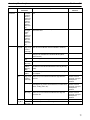
xvi
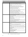
Product Manual name Cat. No. Contents
WS02-LCTC1-EV5
CX-Process Tool
CX-Process Tool
Operation Manual
W372
(this manual)
Installation and operation
procedures for the CX-Process
Tool.
CXONE-ALC-EV
4/ALD-EV4
CX-One FA
Integrated Tool
Package
CXONE-ALC-EV
4/ALD-EV4
CX-One FA
Integrated Tool
Package Setup
Manual
W463 Provides an overview of the
CX-One and describes the
installation procedures for
CX-One software.
Refer to this manual when
installing the CX-Integrator from
the CX-One.
WS02-LCTC1-E
CX-Process Monitor
CX-Process Monitor
Operation Manual
W373 Installation and operation
procedures for the CX-Process
Monitor.
WS02-LCMC1-E
CX-Process Monitor
Plus
CX-Process Monitor
Plus Operation
Manual
W428 Installation and operation
procedures for the CX-Process
Monitor Plus.
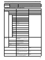
CS1W-LC001
Loop Control Unit
Loop Control Unit
Operation Manual
W374 Installation and operation
procedures for the Loop Control
Unit (except for function blocks).
CS1W-LCB01/05
Loop Control Boards,
CS1D-CPUP
Process-control CPU
Units, and
CJ1G-CPUP
Loop-control CPU
Units
Loop Control Board
Operation Manual
W406 Installation and operation
procedures for the Loop Control
Boards (except for function
blocks).
CS1W-LC001
Loop Control Unit
Loop Control Unit
Function Block
Reference Manual
W375 Detailed information on function
blocks for Loop Control Units.
CS1W-LCB01/05
Loop Control Boards,
CS1D-CPUP
Process-control CPU
Units, and
CJ1G-CPUP
Loop-control CPU
Units
Loop Control Board
Function Block
Reference Manual
W407 Detailed information on function
blocks for Loop Control Boards
CS1W-LCB05-GTC
Loop Control Board
with Gradient
Temperature
Controller
CJ1G-CPU45P-GTC
Loop-control CPU
Unit with Gradient
Temperature
Controller
Loop Control Board
with Gradient
Temperature
Controller
User’s Manual
W460 Provides information required
when using the gradient
temperature control functions. For
information not related to the
gradient temperature control
functions, please refer to the
Loop Control Board Operation
Manual (Cat. No. W406).
For details on procedures for installing the CX-Process Tool from the CX-One FA Integrated Tool Pack-
age, refer to the CX-One Setup Manual provided with CX-One.
Cat. No. Model Manual name Contents
W463 CXONE-ALC-EV
4/ALD-EV4
CX-One Setup
Manual
Installation and overview of
CX-One FA Integrated Tool
Package.

xvii
Section 1 introduces the operations of the CX-Process Tool and connections to the PLC.
Section 2 describes installing the CX-Process Tool and provides an overview of the user interface.
Section 3 describes how to create and manipulate function blocks.
Section 4 describes online operations for uploading, downloading, and testing function block data.
Section 5 describes errors that can occur while using the CX-Process Tool.
WARNING Failure to read and understand the information provided in this manual may result in
personal injury or death, damage to the product, or product failure. Please read each
section in its entirety and be sure you understand the information provided in the section
and related sections before attempting any of the procedures or operations given.
!

xviii

xix
Read and Understand this Manual
Please read and understand this manual before using the product. Please consult your OMRON
representative if you have any questions or comments.
Warranty and Limitations of Liability
WARRANTY
OMRON’s exclusive warranty is that the products are free from defects in materials and workmanship for
a period of one year (or other period if specified) from date of sale by OMRON.
OMRON MAKES NO WARRANTY OR REPRESENTATION, EXPRESS OR IMPLIED, REGARDING
NON-INFRINGEMENT, MERCHANTABILITY, OR FITNESS FOR PARTICULAR PURPOSE OF THE
PRODUCTS. ANY BUYER OR USER ACKNOWLEDGES THAT THE BUYER OR USER ALONE HAS
DETERMINED THAT THE PRODUCTS WILL SUITABLY MEET THE REQUIREMENTS OF THEIR
INTENDED USE. OMRON DISCLAIMS ALL OTHER WARRANTIES, EXPRESS OR IMPLIED.
LIMITATIONS OF LIABILITY
OMRON SHALL NOT BE RESPONSIBLE FOR SPECIAL, INDIRECT, OR CONSEQUENTIAL
DAMAGES, LOSS OF PROFITS OR COMMERCIAL LOSS IN ANY WAY CONNECTED WITH THE
PRODUCTS, WHETHER SUCH CLAIM IS BASED ON CONTRACT, WARRANTY, NEGLIGENCE, OR
STRICT LIABILITY.
In no event shall the responsibility of OMRON for any act exceed the individual price of the product on
which liability is asserted.
IN NO EVENT SHALL OMRON BE RESPONSIBLE FOR WARRANTY, REPAIR, OR OTHER CLAIMS
REGARDING THE PRODUCTS UNLESS OMRON’S ANALYSIS CONFIRMS THAT THE PRODUCTS
WERE PROPERLY HANDLED, STORED, INSTALLED, AND MAINTAINED AND NOT SUBJECT TO
CONTAMINATION, ABUSE, MISUSE, OR INAPPROPRIATE MODIFICATION OR REPAIR.

xx
Application Considerations
SUITABILITY FOR USE
OMRON shall not be responsible for conformity with any standards, codes, or regulations that apply to
the combination of products in the customer’s application or use of the products.
At the customer’s request, OMRON will provide applicable third party certification documents identifying
ratings and limitations of use that apply to the products. This information by itself is not sufficient for a
complete determination of the suitability of the products in combination with the end product, machine,
system, or other application or use.
The following are some examples of applications for which particular attention must be given. This is not
intended to be an exhaustive list of all possible uses of the products, nor is it intended to imply that the
uses listed may be suitable for the products:
•Outdoor use, uses involving potential chemical contamination or electrical interference, or conditions
or uses not described in this manual.
•Nuclear energy control systems, combustion systems, railroad systems, aviation systems, medical
equipment, amusement machines, vehicles, safety equipment, and installations subject to separate
industry or government regulations.
•Systems, machines, and equipment that could present a risk to life or property.
Please know and observe all prohibitions of use applicable to the products.
NEVER USE THE PRODUCTS FOR AN APPLICATION INVOLVING SERIOUS RISK TO LIFE OR
PROPERTY WITHOUT ENSURING THAT THE SYSTEM AS A WHOLE HAS BEEN DESIGNED TO
ADDRESS THE RISKS, AND THAT THE OMRON PRODUCTS ARE PROPERLY RATED AND
INSTALLED FOR THE INTENDED USE WITHIN THE OVERALL EQUIPMENT OR SYSTEM.
PROGRAMMABLE PRODUCTS
OMRON shall not be responsible for the user’s programming of a programmable product, or any
consequence thereof.
Page is loading ...
Page is loading ...
Page is loading ...
Page is loading ...
Page is loading ...
Page is loading ...
Page is loading ...
Page is loading ...
Page is loading ...
Page is loading ...
Page is loading ...
Page is loading ...
Page is loading ...
Page is loading ...
Page is loading ...
Page is loading ...
Page is loading ...
Page is loading ...
Page is loading ...
Page is loading ...
Page is loading ...
Page is loading ...
Page is loading ...
Page is loading ...
Page is loading ...
Page is loading ...
Page is loading ...
Page is loading ...
Page is loading ...
Page is loading ...
Page is loading ...
Page is loading ...
Page is loading ...
Page is loading ...
Page is loading ...
Page is loading ...
Page is loading ...
Page is loading ...
Page is loading ...
Page is loading ...
Page is loading ...
Page is loading ...
Page is loading ...
Page is loading ...
Page is loading ...
Page is loading ...
Page is loading ...
Page is loading ...
Page is loading ...
Page is loading ...
Page is loading ...
Page is loading ...
Page is loading ...
Page is loading ...
Page is loading ...
Page is loading ...
Page is loading ...
Page is loading ...
Page is loading ...
Page is loading ...
Page is loading ...
Page is loading ...
Page is loading ...
Page is loading ...
Page is loading ...
Page is loading ...
Page is loading ...
Page is loading ...
Page is loading ...
Page is loading ...
Page is loading ...
Page is loading ...
Page is loading ...
Page is loading ...
Page is loading ...
Page is loading ...
Page is loading ...
Page is loading ...
Page is loading ...
Page is loading ...
Page is loading ...
Page is loading ...
Page is loading ...
Page is loading ...
Page is loading ...
Page is loading ...
Page is loading ...
Page is loading ...
Page is loading ...
Page is loading ...
Page is loading ...
Page is loading ...
Page is loading ...
Page is loading ...
Page is loading ...
Page is loading ...
Page is loading ...
Page is loading ...
Page is loading ...
Page is loading ...
Page is loading ...
Page is loading ...
Page is loading ...
Page is loading ...
Page is loading ...
Page is loading ...
Page is loading ...
Page is loading ...
Page is loading ...
Page is loading ...
Page is loading ...
Page is loading ...
Page is loading ...
Page is loading ...
Page is loading ...
Page is loading ...
Page is loading ...
Page is loading ...
Page is loading ...
Page is loading ...
Page is loading ...
Page is loading ...
Page is loading ...
Page is loading ...
Page is loading ...
Page is loading ...
Page is loading ...
Page is loading ...
Page is loading ...
Page is loading ...
Page is loading ...
Page is loading ...
Page is loading ...
Page is loading ...
Page is loading ...
Page is loading ...
Page is loading ...
Page is loading ...
Page is loading ...
Page is loading ...
Page is loading ...
Page is loading ...
Page is loading ...
Page is loading ...
Page is loading ...
Page is loading ...
Page is loading ...
Page is loading ...
Page is loading ...
Page is loading ...
Page is loading ...
Page is loading ...
Page is loading ...
Page is loading ...
Page is loading ...
Page is loading ...
Page is loading ...
Page is loading ...
Page is loading ...
Page is loading ...
Page is loading ...
Page is loading ...
Page is loading ...
Page is loading ...
Page is loading ...
Page is loading ...
Page is loading ...
Page is loading ...
Page is loading ...
Page is loading ...
Page is loading ...
Page is loading ...
Page is loading ...
Page is loading ...
Page is loading ...
Page is loading ...
Page is loading ...
Page is loading ...
Page is loading ...
Page is loading ...
Page is loading ...
Page is loading ...
Page is loading ...
Page is loading ...
Page is loading ...
Page is loading ...
Page is loading ...
Page is loading ...
Page is loading ...
Page is loading ...
Page is loading ...
Page is loading ...
Page is loading ...
Page is loading ...
Page is loading ...
Page is loading ...
Page is loading ...
Page is loading ...
Page is loading ...
Page is loading ...
Page is loading ...
Page is loading ...
Page is loading ...
Page is loading ...
Page is loading ...
Page is loading ...
Page is loading ...
Page is loading ...
Page is loading ...
Page is loading ...
Page is loading ...
Page is loading ...
Page is loading ...
Page is loading ...
Page is loading ...
Page is loading ...
Page is loading ...
Page is loading ...
Page is loading ...
Page is loading ...
Page is loading ...
Page is loading ...
Page is loading ...
Page is loading ...
Page is loading ...
Page is loading ...
Page is loading ...
Page is loading ...
Page is loading ...
Page is loading ...
Page is loading ...
Page is loading ...
Page is loading ...
Page is loading ...
Page is loading ...
Page is loading ...
Page is loading ...
Page is loading ...
Page is loading ...
Page is loading ...
Page is loading ...
Page is loading ...
Page is loading ...
Page is loading ...
Page is loading ...
Page is loading ...
Page is loading ...
Page is loading ...
Page is loading ...
Page is loading ...
Page is loading ...
Page is loading ...
Page is loading ...
Page is loading ...
Page is loading ...
Page is loading ...
Page is loading ...
Page is loading ...
Page is loading ...
Page is loading ...
Page is loading ...
Page is loading ...
Page is loading ...
Page is loading ...
Page is loading ...
Page is loading ...
Page is loading ...
Page is loading ...
Page is loading ...
Page is loading ...
Page is loading ...
Page is loading ...
Page is loading ...
Page is loading ...
Page is loading ...
Page is loading ...
Page is loading ...
Page is loading ...
Page is loading ...
Page is loading ...
Page is loading ...
Page is loading ...
Page is loading ...
Page is loading ...
Page is loading ...
Page is loading ...
Page is loading ...
Page is loading ...
Page is loading ...
Page is loading ...
Page is loading ...
Page is loading ...
Page is loading ...
Page is loading ...
Page is loading ...
Page is loading ...
Page is loading ...
Page is loading ...
Page is loading ...
Page is loading ...
Page is loading ...
Page is loading ...
Page is loading ...
Page is loading ...
Page is loading ...
Page is loading ...
Page is loading ...
Page is loading ...
Page is loading ...
Page is loading ...
Page is loading ...
Page is loading ...
Page is loading ...
Page is loading ...
Page is loading ...
Page is loading ...
Page is loading ...
Page is loading ...
Page is loading ...
Page is loading ...
Page is loading ...
Page is loading ...
Page is loading ...
Page is loading ...
Page is loading ...
Page is loading ...
Page is loading ...
Page is loading ...
Page is loading ...
Page is loading ...
Page is loading ...
Page is loading ...
Page is loading ...
Page is loading ...
Page is loading ...
Page is loading ...
Page is loading ...
Page is loading ...
Page is loading ...
Page is loading ...
Page is loading ...
Page is loading ...
Page is loading ...
Page is loading ...
-
 1
1
-
 2
2
-
 3
3
-
 4
4
-
 5
5
-
 6
6
-
 7
7
-
 8
8
-
 9
9
-
 10
10
-
 11
11
-
 12
12
-
 13
13
-
 14
14
-
 15
15
-
 16
16
-
 17
17
-
 18
18
-
 19
19
-
 20
20
-
 21
21
-
 22
22
-
 23
23
-
 24
24
-
 25
25
-
 26
26
-
 27
27
-
 28
28
-
 29
29
-
 30
30
-
 31
31
-
 32
32
-
 33
33
-
 34
34
-
 35
35
-
 36
36
-
 37
37
-
 38
38
-
 39
39
-
 40
40
-
 41
41
-
 42
42
-
 43
43
-
 44
44
-
 45
45
-
 46
46
-
 47
47
-
 48
48
-
 49
49
-
 50
50
-
 51
51
-
 52
52
-
 53
53
-
 54
54
-
 55
55
-
 56
56
-
 57
57
-
 58
58
-
 59
59
-
 60
60
-
 61
61
-
 62
62
-
 63
63
-
 64
64
-
 65
65
-
 66
66
-
 67
67
-
 68
68
-
 69
69
-
 70
70
-
 71
71
-
 72
72
-
 73
73
-
 74
74
-
 75
75
-
 76
76
-
 77
77
-
 78
78
-
 79
79
-
 80
80
-
 81
81
-
 82
82
-
 83
83
-
 84
84
-
 85
85
-
 86
86
-
 87
87
-
 88
88
-
 89
89
-
 90
90
-
 91
91
-
 92
92
-
 93
93
-
 94
94
-
 95
95
-
 96
96
-
 97
97
-
 98
98
-
 99
99
-
 100
100
-
 101
101
-
 102
102
-
 103
103
-
 104
104
-
 105
105
-
 106
106
-
 107
107
-
 108
108
-
 109
109
-
 110
110
-
 111
111
-
 112
112
-
 113
113
-
 114
114
-
 115
115
-
 116
116
-
 117
117
-
 118
118
-
 119
119
-
 120
120
-
 121
121
-
 122
122
-
 123
123
-
 124
124
-
 125
125
-
 126
126
-
 127
127
-
 128
128
-
 129
129
-
 130
130
-
 131
131
-
 132
132
-
 133
133
-
 134
134
-
 135
135
-
 136
136
-
 137
137
-
 138
138
-
 139
139
-
 140
140
-
 141
141
-
 142
142
-
 143
143
-
 144
144
-
 145
145
-
 146
146
-
 147
147
-
 148
148
-
 149
149
-
 150
150
-
 151
151
-
 152
152
-
 153
153
-
 154
154
-
 155
155
-
 156
156
-
 157
157
-
 158
158
-
 159
159
-
 160
160
-
 161
161
-
 162
162
-
 163
163
-
 164
164
-
 165
165
-
 166
166
-
 167
167
-
 168
168
-
 169
169
-
 170
170
-
 171
171
-
 172
172
-
 173
173
-
 174
174
-
 175
175
-
 176
176
-
 177
177
-
 178
178
-
 179
179
-
 180
180
-
 181
181
-
 182
182
-
 183
183
-
 184
184
-
 185
185
-
 186
186
-
 187
187
-
 188
188
-
 189
189
-
 190
190
-
 191
191
-
 192
192
-
 193
193
-
 194
194
-
 195
195
-
 196
196
-
 197
197
-
 198
198
-
 199
199
-
 200
200
-
 201
201
-
 202
202
-
 203
203
-
 204
204
-
 205
205
-
 206
206
-
 207
207
-
 208
208
-
 209
209
-
 210
210
-
 211
211
-
 212
212
-
 213
213
-
 214
214
-
 215
215
-
 216
216
-
 217
217
-
 218
218
-
 219
219
-
 220
220
-
 221
221
-
 222
222
-
 223
223
-
 224
224
-
 225
225
-
 226
226
-
 227
227
-
 228
228
-
 229
229
-
 230
230
-
 231
231
-
 232
232
-
 233
233
-
 234
234
-
 235
235
-
 236
236
-
 237
237
-
 238
238
-
 239
239
-
 240
240
-
 241
241
-
 242
242
-
 243
243
-
 244
244
-
 245
245
-
 246
246
-
 247
247
-
 248
248
-
 249
249
-
 250
250
-
 251
251
-
 252
252
-
 253
253
-
 254
254
-
 255
255
-
 256
256
-
 257
257
-
 258
258
-
 259
259
-
 260
260
-
 261
261
-
 262
262
-
 263
263
-
 264
264
-
 265
265
-
 266
266
-
 267
267
-
 268
268
-
 269
269
-
 270
270
-
 271
271
-
 272
272
-
 273
273
-
 274
274
-
 275
275
-
 276
276
-
 277
277
-
 278
278
-
 279
279
-
 280
280
-
 281
281
-
 282
282
-
 283
283
-
 284
284
-
 285
285
-
 286
286
-
 287
287
-
 288
288
-
 289
289
-
 290
290
-
 291
291
-
 292
292
-
 293
293
-
 294
294
-
 295
295
-
 296
296
-
 297
297
-
 298
298
-
 299
299
-
 300
300
-
 301
301
-
 302
302
-
 303
303
-
 304
304
-
 305
305
-
 306
306
-
 307
307
-
 308
308
-
 309
309
-
 310
310
-
 311
311
-
 312
312
-
 313
313
-
 314
314
-
 315
315
-
 316
316
-
 317
317
-
 318
318
-
 319
319
-
 320
320
-
 321
321
-
 322
322
-
 323
323
-
 324
324
-
 325
325
-
 326
326
-
 327
327
-
 328
328
-
 329
329
-
 330
330
-
 331
331
-
 332
332
-
 333
333
-
 334
334
-
 335
335
-
 336
336
-
 337
337
-
 338
338
-
 339
339
-
 340
340
-
 341
341
-
 342
342
-
 343
343
-
 344
344
-
 345
345
-
 346
346
-
 347
347
-
 348
348
-
 349
349
-
 350
350
-
 351
351
-
 352
352
-
 353
353
-
 354
354
-
 355
355
-
 356
356
-
 357
357
-
 358
358
-
 359
359
-
 360
360
-
 361
361
-
 362
362
-
 363
363
-
 364
364


Omron CX-Process Tool 5.2 User manual
- Category
- Software
- Type
- User manual
- This manual is also suitable for
Ask a question and I''ll find the answer in the document
Finding information in a document is now easier with AI
Related papers
-
Omron Sysmac CS/CJ Series Operating instructions
-
-
-
-
-
-
-
-
-
Other documents
-
Pro-face BLUE Open Studio 2023 Owner's manual
-
 Paradyne COMSPHERE 3825Plus User manual
-
Paradyne COMSPHERE 3821PLUS User manual
-
-
-
 Paradyne WIRELESS DATA GATEWAY Operating instructions
-
Azbil C7G User manual
-
Panasonic DX1000 Operating instructions
-
Paradyne COMSPHERE 3921Plus Operating instructions
-

