Page is loading ...

Thank you for purchasing your Azbil
Corporation product.
This manual contains information for
ensuring the safe and correct use of
the product.
Those designing or maintaining
equipment that uses this product
should first read and understand
this manual. This manual contains
information not only for installation,
but also for maintenance,
troubleshooting, etc. Be sure to keep it
nearby for handy reference.
(Not for use in Japan) No. CP-SP-1402E
Multi-loop Controller with
Multifunction Display
Model C7G
Installation and
Configuration Manual

NOTICE
Please make sure that this manual is available to the user of the product.
Unauthorized duplication of this user’s manual in part or in whole is
forbidden. The information and specifications in this manual are subject to
change without notice.
Considerable effort has been made to ensure that this manual is complete
and accurate, but if you should find an omission or error, please contact us.
In no event is Azbil Corporation liable to anyone for any indirect, special, or
consequential damages as a result of using this product.
© 2017–2023 Azbil Corporation. All Rights Reserved.

i
Safety Requirements
To reduce the risk of an electric shock that could cause personal injury,
follow all safety notices in this document.
This symbol warns the user of a potential shock hazard where hazardous
live voltages may be accessible.
Use of this product in a manner not specified by the manufacturer will impair its built-in safety features.
Do not replace any component except as specified by the manufacturer.
All wiring work must comply with local regulations and be carried out by authorized and experienced personnel.
Make sure to provide a cutoff switch for the power to this device within reach of the operator.
Do not remove blocks except to replace them. Replacement of the CLOCK block (p.11-1) and
Replacing the MOTOR block (p.11-1) (for information on replacement blocks)
For DC models, connect a Class II power supply unit.
z Equipment Ratings
Ingress protection: IP67 (display unit)
z AC power
Supply voltage: 100–240 V AC (operating voltage: 85–264 V AC)
Power supply frequency: 50/60 Hz
Power consumption: 25 VA max. 10 W max.
z DC power
Supply voltage: 24 V DC (operating voltage: 20.4 to 28.8 V DC)
Power consumption: 12 W max.
z Environmental conditions
Do not use this device near corrosive gases, flammable fluids or vapors, or in wet places. Also, do
not touch it with wet hands.
Operating temperature: 0 to 50 ˚C (0 to 40 ˚C if main units are gang-mounted)
Operating humidity: 10 to 90 % RH (without condensation)
Vibration: 5 m/s2 (10 to 60 Hz)
Overvoltage: Category II (IEC 60364-4-443, IEC 60664-1)
Pollution degree: 2
Installation location: Indoors
Elevation: 2000 m max.
Ventilation space: For the main unit, leave at least 50 mm above, below, and in front of the
unit. No space is needed on the right or left.
For the display unit, no space is needed above, below, on the right, or on the left.
z Equipment Installation
Excluding the supplied power, the I/O common mode voltage with respect to the ground should be
30 Vrms max., 42.4 V peak max., and 60 V DC max.
z Standards Compliance
EN 61010-1, EN 61326-1 (for use in industrial locations)
During EMC testing, the reading or output may fluctuate by ±10 % FS.
UL 61010-1, CAN/CSA C22.2 No. 61010-1 (UL-compliant models only)

ii
Conventions Used in This Manual
The safety precautions explained below aim to prevent injury to you and others, and to prevent property damage.
WARNING Warnings are indicated when mishandling this
product may result in death or serious injury.
CAUTION Cautions are indicated when mishandling this
product may result in minor injury or property
damage only.
In describing the product, this manual uses the icons and wording listed below.
Indicates that caution is required in handling.
The indicated action is prohibited.
Be sure to follow the indicated instructions.
Handling Precautions:
Precaution is required in handling.
Note:Indicates information that may be useful.
: Indicates an item or page to which the user may refer.
(1) (2) (3): Numbers inside parentheses indicate steps in a sequence or parts of an explanation.
[XXX] button: Square brackets indicate buttons at the bottom of the display unit or buttons and
messages shown on the display unit screen.
[XXX] window,
[XXX]
Square brackets indicate a window name, message, or menu, shown on the PC screen.
>> : Indicates the result of an operation, or the status after the operation.

iii
Safety Precautions
WARNING
Do not use this device in an environment with conductive pollution, or with dry non-
conductive pollution which can become conductive due to condensation, etc. Otherwise,
problems such as tracking phenomena may damage parts, resulting in fire.
Make sure that the frame ground terminal is properly grounded (100 Ω max.) before
connecting the controller to the measurement target or to external control circuits.
Be sure to check that the device has been correctly wired before turning on the power.
Incorrect wiring of this device may cause device failure and also lead to a dangerous accident.
Before removing, mounting, or wiring the device, be sure to turn off the power to this device
and any connected devices. Otherwise, there is a danger of electric shock.
Do not touch electrically charged parts such as the power terminals. There is a danger of
electric shock.
Do not disassemble this device. There is a danger of electric shock or device failure.
To prevent electrical shock, the main unit of this product must be installed in a location that is
only accessible to people with appropriate knowledge about electrical safety. Install the main
unit inside a control panel that cannot be opened without the use of a key or tool.
Also, before touching electrically charged components such as the input terminal block for
AC power, be sure to turn off the power. After checking that the voltage has dropped, work
carefully to prevent electrical shock. Always keep the cover on the power input terminal
block. Otherwise, there is a danger of fire or electric shock.
CAUTION
Use this device within the operating ranges given in the specifications (for temperature,
humidity, voltage, vibration, shock, mounting direction, atmosphere, etc.). Otherwise, there
is a danger of fire or device failure.
Wire this device correctly by using the wiring method, power, and installation method
specified in this user’s manual. Otherwise, there is a danger of fire, electric shock, or device
failure.
Do not allow wire clippings, metal shavings, water, etc., to enter the case of this device. There
is a danger of fire or device failure.
Firmly tighten the terminal screws to the torque listed in the specifications. Insufficient
tightening may cause fire or electric shock.
Do not use unused terminals as relay terminals. There is a danger of fire, electric shock, or
device failure.
If the lithium battery used in this device is packaged together with it (installed) and
transported by air or ship, be sure that it is transported in accordance with the IATA DGR/
IMDG Code.
Do not block the ventilation holes. There is a danger of fire or device failure.

iv
CAUTION
Do not operate the buttons or the touch panel with a sharp object (such as a mechanical
pencil tip, etc.). Doing so can cause device failure.
The frame ground terminal of this device is a functional ground. Ground the frame ground
terminal to suppress adverse effects from external noise. Otherwise, malfunction may result.
Be sure that the settings are correct for the sensor type. If the settings are incorrect, the
normal PV will not be measured correctly. In that case a dangerous situation such as constant
100 % control output could occur.

v
• Notice on use of licensed software of ARM.
This product uses the software according to the license of ARM in a part of the software. The following contents are based on the license
agreement, which does not prescribe customers’ usage restrictions.
Copyright © 2009 - 2015 ARM LIMITED All rights reserved.
Redistribution and use in source and binary forms, with or without modification, are permitted provided that the following conditions are
met:
- Redistributions of source code must retain the above copyright notice, this list of conditions and the following disclaimer.
- Redistributions in binary form must reproduce the above copyright notice, this list of conditions and the following disclaimer in the
documentation and/or other materials provided with the distribution.
- Neither the name of ARM nor the names of its contributors may be used to endorse or promote products derived from this software
without specific prior written permission.
THIS SOFTWARE IS PROVIDED BY THE COPYRIGHT HOLDERS AND CONTRIBUTORS “AS IS” AND ANY EXPRESS OR IMPLIED WARRANTIES,
INCLUDING, BUT NOT LIMITED TO, THE IMPLIED WARRANTIES OF MERCHANTABILITY AND FITNESS FOR A PARTICULAR PURPOSE ARE
DISCLAIMED. IN NO EVENT SHALL COPYRIGHT HOLDERS AND CONTRIBUTORS BE LIABLE FOR ANY DIRECT, INDIRECT, INCIDENTAL, SPECIAL,
EXEMPLARY, OR CONSEQUENTIAL DAMAGES (INCLUDING, BUT NOT LIMITED TO, PROCUREMENT OF SUBSTITUTE GOODS OR SERVICES;
LOSS OF USE, DATA, OR PROFITS; OR BUSINESS INTERRUPTION) HOWEVER CAUSED AND ON ANY THEORY OF LIABILITY, WHETHER
IN CONTRACT, STRICT LIABILITY, OR TORT (INCLUDING NEGLIGENCE OR OTHERWISE) ARISING IN ANY WAY OUT OF THE USE OF THIS
SOFTWARE, EVEN IF ADVISED OF THE POSSIBILITY OF SUCH DAMAGE.
• Notice regarding use of licensed software of STMicroelectronics.
This product uses the software according to the license of STMicroelectronics in a part of the software. The following contents are based
on the license agreement, which does not prescribe customers’ usage restrictions.
COPYRIGHT© 2014 STMicroelectronics
Redistribution and use in source and binary forms, with or without modification,are permitted provided that the following conditions are
met:
1. Redistributions of source code must retain the above copyright notice,this list of conditions and the following disclaimer.
2. Redistributions in binary form must reproduce the above copyright notice,this list of conditions and the following disclaimer in the
documentation and/or other materials provided with the distribution.
3. Neither the name of STMicroelectronics nor the names of its contributors may be used to endorse or promote products derived from
this software without specific prior written permission.
THIS SOFTWARE IS PROVIDED BY THE COPYRIGHT HOLDERS AND CONTRIBUTORS “AS IS”AND ANY EXPRESS OR IMPLIED WARRANTIES,
INCLUDING, BUT NOT LIMITED TO, THE IMPLIED WARRANTIES OF MERCHANTABILITY AND FITNESS FOR A PARTICULAR PURPOSE ARE
DISCLAIMED. IN NO EVENT SHALL THE COPYRIGHT HOLDER OR CONTRIBUTORS BE LIABLE FOR ANY DIRECT, INDIRECT, INCIDENTAL,
SPECIAL, EXEMPLARY, OR CONSEQUENTIAL DAMAGES (INCLUDING, BUT NOT LIMITED TO, PROCUREMENT OF SUBSTITUTE GOODS
OR SERVICES; LOSS OF USE, DATA, OR PROFITS; OR BUSINESS INTERRUPTION) HOWEVER CAUSED AND ON ANY THEORY OF LIABILITY,
WHETHER IN CONTRACT, STRICT LIABILITY,OR TORT (INCLUDING NEGLIGENCE OR OTHERWISE) ARISING IN ANY WAY OUT OF THE USE OF
THIS SOFTWARE, EVEN IF ADVISED OF THE POSSIBILITY OF SUCH DAMAGE.
• microSD is trademark or registered trademark of SD-3C, LLC in the United States, other countries or both.
• MELSEC and SLMP are trademarks of Mitsubishi Electric Corporation.
• Ethernet is a trademark of FUJIFILM Business Innovation Corp.
• ModbusTM is a trademark and the property of Schneider Electric SE, its subsidiaries and affiliated companies.
Copyright, licenses, and trademarks

vi
Contents
Safety Requirements
Conventions Used in This Manual
Safety Precautions
Copyright, licenses, and trademarks
Chapter 1. Overview 1-1
1 - 1 Overview 1-1
1 - 2 Model No. 1-2
Model Selection Guide 1-2
Optional Parts (Sold Separately) 1-5
1 - 3 Names of Parts and Their Functions 1-6
Display unit 1-6
Main unit 1-6
Integrating bracket 1-6
1 - 4 Input/output Configuration 1-7
1 - 5 Button Operation 1-9
Screen transitions 1-9
Parameter bank 1-10
Japanese language display 1-15
Monitor and graph screen transitions 1-16
Screen transitions of the user HOME screen 1-20
1 - 6 Operation Modes 1-22
Chapter 2. Mounting 2-1
2 - 1 External View and Mounting Dimensions 2-1
Standard mounting 2-1
Integrated mounting 2-1
Mounting locations 2-1
2 - 2 Mounting Method 2-2
Standard mounting 2-2
Integrated mounting 2-5
Chapter 3. Wiring 3-1
3 - 1 Wiring Precautions 3-1
Wiring precautions 3-2
3 - 2 Recommended Cables 3-3
3 - 3 Crimp Terminals / Ferrules 3-4
Crimp terminals 3-4
Ferrules 3-5
Inserting ferrules 3-6
Removing ferrules 3-6
3 - 4 Wiring 3-7
Noise suppression measures 3-7

vii
Power input 3-8
Grounding 3-8
DI/DO block (7 digital inputs or outputs, selectable) 3-9
RS-485 (RS-485 communication port) 3-10
Analog input block (analog input) 3-11
Analog input block layout 3-12
Analog output block (current outputs, CT inputs, and VT inputs) 3-13
Voltage pulse output block (voltage pulse outputs and 2 CT inputs) 3-14
DI block (4 digital inputs) 3-18
DO block (4 digital outputs, sink output) 3-18
MOTOR block (motor drive outputs and motor feedback inputs) 3-19
I/O isolation 3-20
USB connection 3-20
Inserting or removing a microSD memory card 3-21
Connecting the LAN cable for Ethernet 3-21
Connecting the cable between the main unit and display unit 3-22
Chapter 4. Functions 4-1
4 - 1 Loop Types 4-1
Model numbers and loop types 4-1
Setting the loop type 4-4
4 - 2 AI (Analog Input) 4-5
Range types 4-6
Linear scaling low and high limits 4-6
Setting the linear input unit character 4-6
Filter 4-7
Ratio and bias 4-8
Square root extraction dropout 4-8
Linearization table group definition 4-9
Number of decimal places for PV 4-10
Sampling cycle 4-10
PV Hold 4-11
Power supply frequency 4-11
Alarm low and high limits 4-11
Low and high limits 4-11
4 - 3 Mode 4-12
AUTO/MANUAL mode 4-12
Constant value operation / Pattern operation 4-13
RUN/READY mode 4-14
LSP/RSP mode 4-14
Pattern start number 4-15
READY/RUN/HOLD/END mode 4-15
ADVANCE 4-17
G.SOAK clear 4-18
AT (auto-tuning) stop/start 4-18

viii
4 - 4 Control 4-19
Functional block diagram of PID control 4-19
Functional block diagram of ON/OFF control 4-20
Functional block diagram of heating/cooling control 4-21
Control action 4-22
Heating/cooling control dead zone 4-22
Fixed value output 4-23
Special control output 4-24
When switching to MANUAL mode 4-24
PID control initialization 4-25
PID initial MV 4-25
MV change limit 4-26
PID control 4-26
Zone PID 4-27
MV tracking 4-28
SP lag 4-32
ON/OFF control 4-33
4 - 5 AT (Auto-tuning) 4-37
AT (Auto-tuning) 4-37
How to start 4-38
How to stop AT 4-38
4 - 6 SP 4-41
Setting the LSP from the 1-loop monitor screen 4-42
Selecting LSP group and RSP from the 1-loop monitor screen 4-42
Number of LSP system groups 4-42
RSP setting 4-42
LSP1 to 8 and RSP 4-43
PID group number 4-43
LSP group No. 4-44
DI assignment for LSP group selection 4-44
SP ramp unit 4-45
SP ramp up and down slopes 4-46
SP low and high limits 4-47
RSP tracking 4-47
4 - 7 Pattern Operation 4-48
Pattern 4-49
Time unit for patterns 4-49
Number of segments 4-50
SP/Time 4-50
PID group number 4-51
G.SOAK (Guarantee Soak) 4-52
Segment event 4-53
PV start 4-54
Cycle 4-54
Pattern link 4-55
End of operation 4-56
Pattern start number 4-57
Pattern SP increase/decrease change limit 4-59

ix
4 - 8 DI (Digital Input) 4-60
DI/DO configuration 4-60
DI assignment 4-61
4 - 9 Events 4-66
Operation 4-67
Operation type and Loop definition 4-72
Direct/reverse, Standby, and READY mode operation 4-73
Event main setting, event subsetting, hysteresis, delay 4-75
4 - 10 DO (Digital Output) 4-76
DI/DO configuration 4-76
DO assignment 4-77
4 - 11 TP (Time Proportioning) Output 4-79
DI/DO configuration 4-80
TP output type 4-81
TP cycle 4-82
TP operation type 4-82
Linearization table group definition 4-83
Power supply voltage compansation (slot selection) 4-84
4 - 12 Analog Output (AO) 4-85
Output range 4-85
Output type 4-85
Loop definition 4-86
Output scaling low and high limits 4-86
Linearization table group definition 4-87
Power supply voltage compansation (slot selection) 4-88
4 - 13 Motor Drive Output (Position Proportional Control) 4-89
Output type 4-89
Control method 4-90
MFB AT (MFB auto-tuning) 4-91
MFB adjustment value 4-93
Dead zone 4-93
Linearization table group definition 4-94
4 - 14 CT (Current Transformer) Input 4-95
Number of turns and number of power wire loops 4-95
CT input display range and current measurement range 4-96
CT input filter 4-96
Current measurement and error detection 4-97
Condition for restoring status before measurement 4-102
Timing for updating CT current measurement 4-102
4 - 15 VT (Voltage Transformer) Input 4-103
Primary voltage and secondary voltage 4-103
Power supply voltage compansation 4-104
4 - 16 Linear Approximation 4-105
Linearization by specifying breakpoints 4-105
Linearization by specifying bias 4-106
Example using linear approximation by analog input 4-106
Example using linear approximation for analog output 4-107

x
When the increase in magnitude of the breakpoints on the A-axis is not in
numerical order 4-109
When two adjacent breakpoints have the same value on the A-axis 4-109
4 - 17 Internal Cascade 4-110
Master/Slave 4-110
Loop Types 4-110
Example: Internal cascade settings 4-111
4 - 18 Logical Operations 4-113
Processing order for logical operations 4-113
Calculation type 4-114
Input assignments A, B, C, and D 4-114
Input bit polarities A, B, C, and D 4-114
Reverse 4-115
ON/OFF delay 4-115
Latch 4-116
4 - 19 Numerical Operations 4-117
Processing order for numerical operations 4-117
Operation type 4-118
Details of numerical operations 4-119
When an error occurs 4-143
Input type 4-143
4 - 20 CDS (Compact Data Storage) 4-144
Recording cycle/operation type 4-144
Data selection 4-145
Number of data / Data1 to Data40 4-146
Screen during CDS operation 4-148
Files 4-149
Customizing the number of data items and data types 4-153
Setting the date and time by the SLP-C7 4-155
microSD memory card operations from SLP-C7 4-156
Specifications of older versions 4-157
4 - 21 Health Index 4-158
R value 4-158
Settings 4-158
Operation 4-159
Graph display 4-160
4 - 22 Display Unit Adjustment 4-161
Brightness adjustment 4-161
Position adjustment 4-161
4 - 23 Advanced Loop Type Setting 4-163
Loop types 4-163
Input assignment 4-163
Virtual AI (analog Input) 4-165
setting 4-167
Lock and unlock with the password 4-167
4 - 24 Lock and Password 4-167
Resetting the lock level and password using the SLP-C7 4-168
Setting [LOCK level] and [Password] using the SLP-C7 4-168

xi
4 - 25 Feed Forward Fitter (FF-FITTER) 4-169
Start and stop 4-170
Conditions for executing FF-FITTER 4-170
Standard application 4-171
Advanced use 4-173
Auto-tuning 4-174
Chapter 5. Screens 5-1
5 - 1 Monitor Screen and Graph Screen 5-1
Home screen 5-1
1-loop monitor screen 5-10
Pattern operation monitor screen 5-13
Multi-loop graph screen 5-16
1-loop graph screen 5-18
1-loop monitor screen in MANUAL mode 5-19
1-loop monitor screen during AT execution 5-20
1-loop monitor screen when MFB AT is stopped 5-21
1-loop monitor screen during MFB AT 5-22
Screen at key lock 5-23
1-loop monitor screen if there is an alarm 5-24
Block alarm screen 5-25
Function alarm screen 5-26
SP menu screen 5-27
LSP/RSP select screen 5-28
LSP setting change screen 5-29
Constant value operation / pattern operation switching screen 5-31
Pattern operation mode selection screen 5-32
Constant value operation mode selection screen 5-33
Mode menu screen 5-34
Mode menu screen (pattern) 5-35
AUTO/MANUAL change screen 5-36
RUN/READY change screen 5-37
AT start/stop screen 5-38
HOLD mode change screen 5-39
ADVANCE operation screen 5-40
G.SOAK clear screen 5-41
DI/DO monitor screen 5-42
DI monitor screen 5-43
DO monitor screen 5-44
EV monitor screen 5-45
SEG-EV monitor screen 5-46
5 - 2 Parameter screen 5-47
Parameter bank menu screen 5-47
Parameter item menu screen 5-48
Parameter item setting change screen 5-49
Pattern settings/segment settings 5-50

xii
IP address 5-52
Date and Time 5-53
Firmware Versions 5-55
Chapter 6. Display and Setting Data 6-1
6 - 1 Operation Display Data 6-1
Home screen 6-1
1-loop monitor screen 6-2
Graph screen 6-5
6 - 2 Parameter Setting Display Data 6-6
SP bank 6-6
Event bank 6-7
PID bank 6-7
Analog input bank 6-8
Basic action bank 6-9
Control bank 6-12
SP configuration bank 6-15
Analog output bank 6-16
Event configuration bank 6-18
DI/DO configuration bank 6-20
DO configuration bank 6-21
DI bank 6-22
TP (time proportioning) bank 6-25
Logical operation bank 6-29
Numerical operation bank 6-30
User-defined bit bank 6-31
User-defined value bank 6-33
User-defined alarm bank 6-35
CT input bank 6-36
VT input bank 6-37
PP (position proportional) bank 6-38
Linearization table bank 6-40
Cascade bank 6-41
Graph bank 6-42
Ethernet bank 6-42
IP address bank 6-43
RS-485 bank 6-43
CDS bank 6-44
Health index bank 6-46
Health index graph bank 6-47
Date and time bank 6-47
Input assignment bank 6-48
Virtual analog input bank 6-50
Feed forward fitter bank 6-52
6 - 3 Pattern Setting Display Data 6-54
Pattern configuration bank 6-54

xiii
Pattern bank 6-55
Segment bank 6-56
6 - 4 Parameter Data for Communication 6-57
Monitor (RAM)/Loop1 to 4 6-57
Monitor/Mode 6-57
Monitor/Operation display (Loop1 to 4) 6-58
Monitor/Operation display (AO-C block) 6-58
Monitor/operation display (V-P block) 6-59
Monitor/Status (DI/DO block) 6-59
Monitor/Status (Events 1 to 16) 6-60
Monitor/Status (other) 6-60
Alarm condition 6-61
Monitor/Position proportional 6-61
Monitor/Pattern mode 6-62
Monitor/Pattern monitor 6-62
Monitor/Segment event 6-63
SP Configuration (LSP group selection) 6-63
User-defined bits (RAM) 6-64
User-defined values(RAM) 6-65
Device info. 6-65
Standard bits 6-66
Standard numerical code 6-66
Chapter 7. Modbus RTU Communication Functions 7-1
7 - 1 Overview of Communications 7-1
Features 7-1
Settings 7-2
Communication procedure 7-2
7 - 2 Message Structure 7-3
Message structure 7-3
Command type 7-4
Exception codes 7-4
Amount of data 7-5
7 - 3 Description of Commands 7-6
Multiple data read command (03H) 7-6
Multiple data write command (10H) 7-7
1 data write command (06H) 7-8
7 - 4 Numeric Value Expression 7-9
Hexadecimal 7-9
7 - 5 Send/Receive Timing 7-10
Time specifications for instruction and response messages 7-10
Specifications of RS-485 driver control timing 7-10
Chapter 8. Modbus TCP Communication Functions 8-1
8 - 1 Overview of Communications 8-1

xiv
Features 8-1
Settings 8-1
Communication procedure 8-2
General TCP/IP socket communication procedure 8-2
8 - 2 Message structure 8-3
Message structure 8-3
Exception code 8-4
Amount of data 8-5
8 - 3 Description of Commands 8-6
Application section 8-6
Multiple data read command (03H) 8-6
Multiple data write command (10H) 8-7
1 data write command (06H) 8-8
Chapter 9. User-defined Addresses 9-1
9 - 1 Overview of User-defined Addresses 9-1
User-defined addresses 9-1
9 - 2 Address Definition Method 9-2
Setting a user-defined address 9-2
Changing the data address display system 9-4
Normal memory area and RAM area 9-4
Precautions when using both the normal memory area and the RAM area for
the same parameter 9-6
Bit fields 9-8
9 - 3 Initial Values of User-Defined Addresses 9-12
9 - 4 Reception Monitoring 9-14
Reception monitoring settings 9-14
9 - 5 Pattern Communication Data 9-16
Data address overview 9-16
Decimal point 9-17
PATTERN COMMUNICATION SETUP 9-17
Pattern communication access procedure 9-18
Data address details 9-19
Chapter 10. PLC Link Communication 10-1
10 - 1 Data Transfer 10-1
Connectible PLCs 10-4
Usable devices 10-5
Completion notification data 10-7
10 - 2 PLC Link Setting Method 10-8
Common settings 10-8
Transfer settings 10-9
Transfer setting examples 10-10
10 - 3 List of PLC Link Settings 10-15
PLC connection settings 10-15

xv
Transfer settings 10-15
Data settings 10-16
10 - 4 Mitsubishi PLC 10-17
iQ-R series CPU direct connection 10-17
Q series CPU direct connection 10-20
Q series Ethernet interface module 10-24
iQ-F series CPU direct connection 10-28
10 - 5 Keyence PLC 10-32
CPU direct connection 10-32
Chapter 11. Maintenance and Troubleshooting 11-1
11 - 1 Maintenance 11-1
Cleaning 11-1
Parts replacement 11-1
Replacement of the CLOCK block 11-1
Replacing the MOTOR block 11-1
11 - 2 Alarm 11-2
Block alarm screen 11-2
Block alarm 11-3
Function alarm screen 11-5
Function alarm 11-6
11 - 3 Display Error 11-7
Display unit does not work. 11-7
Nothing is shown on display unit. 11-7
An error is indicated on the display unit 11-7
The firmware version of the display unit does not match. 11-8
Checking and updating the firmware version using the SLP-C7 11-8
Chapter 12. DISPOSAL 12-1
Removing the battery for product disposal 12-1
Chapter 13. Specifications 13-1
Specifications 13-1
Input types and ranges 13-13
Input sensor standards 13-14
Chapter 14. Appendix 14-1
14 - 1 Function Block Diagrams 14-1
Processing procedure 14-1
AI (analog input) process block diagram 14-3
SP process / PID process block diagram 14-4
AO (analog output) process block diagram 14-5

xvi
TP (time proportioning) output process block diagram 14-6
PP (position proportional) output process block diagram 14-7
14 - 2 Standard Bit Codes and Standard Numerical Codes 14-8
Standard bit codes 14-8
Standard numerical codes 14-16
14 - 3 Precautions for Communication Function 14-21
Examples of operations when using both the normal memory area and RAM
area for the same parameter 14-21
14 - 4 Firmware Version History 14-24
Support start date: September 2016 14-24
Support start date: December 2016 14-26
Support start date: June 2017 14-29
Support start date: August 2017 14-33
Support start date: August 2018 14-37
Support start date: March 2019 14-43
Support start date: January 2020 14-44
Support start date: May 2021 14-45
14 - 5 Abbreviations and Terms 14-47

1-1
Chapter 1. Overview
1 - 1 Overview
The C7G multi-loop controller with multifunction display (hereafter also called simply "this device" or "C7G" or
"C7") can calculate diagnostic parameters, known collectively as the health index, that help to predict failure of other
equipment, in addition to calculations for PID (proportional, integral and derivative) control of process variables
such as temperature, pressure, flow rate, pH, and liquid level.
This product consists of a display unit with a 3.5-inch QVGA LCD touch panel, as well as a main unit capable of
controlling up to four loops with an input sampling cycle of 10 ms and an indication accuracy of ± 0.1 % FS.
The display unit and main unit can be installed separately for installation flexibility.
A wide variety of interfaces, including Ethernet, RS-485 serial communication, microSD memory card, micro USB
port, and 7 digital input/outputs are provided as standard features.
Setup, operation, and monitoring can be easily accomplished using the display unit and Smart Loader Package.
This controller is compliant with IEC directives and is CE marked.

1-2
Chapter 1. Overview
1 - 2 Model No.
Model Selection Guide
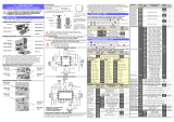
z Block name
Symbol Block Name Description
AI Analog input Full multi-range input (thermocouple, RTD, DC current, DC voltage)
V-P Voltage pulse
output
Voltage pulse output (12 V DC)
2 input terminals for the current transformer (CT) for detecting heater burnout,
overcurrent, and short circuits*1
AO-C Analog current
output
Current output (4–20 mA DC / 0–20 mA DC)
Input terminals for the current transformer (CT) for measuring current and the voltage
transformer (VT) for measuring voltage (1 each)*1
HMI2 Additional
display unit
Connector for the second display unit*2
CLOCK Clock function Clock (available for CDS and health index) with a battery
MOTOR Motor drive
output
Motor drive outputs (100/200 V AC) (direct (OPEN), reverse (CLOSE))
with motor feedback (MFB) inputs
DI Digital input 4 digital inputs (external power source required)
DO Digital output 4 digital outputs (sink output)
*1. Current transformer (CT) and voltage transformer (VT) are sold separately.
*2. Additional display unit is sold separately.
z Accessories
Part name
Qty.
Notes
Standard (separate)
mounting model
(C7G_4)
Integrated mounting
model
(C7G_3)
Main unit 1 1
Display unit 1 1
Standard gasket 1 0 Mounted on the display unit
Gasket with 92 × 92 mm hole 0 1
Display unit mounting screws
(6 mm)
5 5 4 screws plus 1 spare
Display unit mounting screw
(10 mm)
5 0 4 screws plus 1 spare
Setscrew for temporary
mounting
2 0
Integrating bracket 0 1
Integrating cable 0 1
Installation Manual 1 1 Document No. CP-UM-5847JE
Instruction for safe use 1 1 Document No. CP-UM-5824EGFIS
/