Page is loading ...

User Manual
ADA-1010
Separator – Repeater RS-232
1
ADA-1010
Copyright © 2001-2020 CEL-MAR sp.j. io_ada-1010_v3.21_en

Contents
1. GENERAL INFORMATION..................................................................................................................................................................... 3
1.1. WARRANTED INFORMATION...................................................................................................................................................... 3
1.2. GENERAL CONDITIONS FOR SAFE USE...................................................................................................................................3
1.3. CE LABEL...................................................................................................................................................................................... 3
1.4. ENVIRONMENTAL PRESERVATION...........................................................................................................................................3
1.5. SERVICE AND MAINTENANCE.................................................................................................................................................... 3
1.6. PACK CONTENTS......................................................................................................................................................................... 3
2. PRODUCT INFORMATION.................................................................................................................................................................... 3
2.1. PROPERTIES................................................................................................................................................................................ 3
2.2. DESCRIPTION............................................................................................................................................................................... 4
2.3. ISOLATION.................................................................................................................................................................................... 4
3. INSTALLATION...................................................................................................................................................................................... 5
3.1. ASSEMBLING................................................................................................................................................................................ 5
3.2. CONNECTION OF DEVICES WITH RS232 INTERFACE TO 'IN' PORT OF REPEATER...........................................................5
3.2.1. CONNECTION OF DEVICES WITH RS232 PORT - DTE TYPE (COMPUTER)..................................................................5
3.2.2. CONNECTION OF DEVICES WITH RS232 PORT - DCE TYPE (MODEM)........................................................................5
3.3. EXAMPLE CONNECTIONS OF DEVICES TO ADA-1010 REPEATER........................................................................................6
3.3.1. SEPARATION OF RS232 COMPUTER PORT.....................................................................................................................6
3.3.2. RS232 PORT EXTENSION UP TO 45M...............................................................................................................................6
3.3.3. RS232 PORT EXTENSION UP TO 300m.............................................................................................................................6
3.4. POWER SUPPLY CONNECTION.................................................................................................................................................8
4. ACTIVATION.......................................................................................................................................................................................... 8
5. PIN DESCRIPTION OF DSUB-9F-DCE SOCKET.................................................................................................................................8
6. DESCRIPTION OF SCREW TERMINAL BLOCK.................................................................................................................................. 8
7. VERSIONS............................................................................................................................................................................................. 9
8. SPECIFICATION.................................................................................................................................................................................... 9
2
ADA-1010

1. GENERAL INFORMATION
Thank you for your purchase of CEL-MAR Company product. This product has been completely tested and is covered by a two year
warranty on parts and operation from date of sale.
Any questions or detailed technical information about the use of this product can be obtained by contacting ‘Technical Support’ by
telephone: +48 41 362-12-46 or email: support@cel-mar.pl.
1.1. WARRANTED INFORMATION
ADA-1010 repeater is covered by a two year warranty from date of sale. If the product malfunctions or does not operate in
accordance with the instructions, it will be repair or replace at its discretion of CEL-MAR Company. The warranty does not cover
damage caused from improper use, materials wear or any unauthorized changes.
All returns must be via paid transport and insurance (by the sender) to the CEL-MAR Company.
CEL-MAR Company under no circumstances is responsible for repairs arising from damage through improper use or as a result of
lightning, flood, rising water, fire (electrical or other heat/radiation exposure) or like events.
CEL-MAR Company is not liable for damages and loss including but not limited to: loss of profits, loss of data, pecuniary losses
ensuing from using or improper use of its product.
In specific cases, CEL-MAR Company will discontinue all warranty claims if it finds the device was used in a manner not described in
the user manual and may refuse further claims of warranty by the user.
1.2. GENERAL CONDITIONS FOR SAFE USE
The device should be installed in a safe and stable place (e.g, electrical installation cabinet). Power and signal cables should be
arranged so as not to be exposed to trampling, vandalism or unreasonable mechanical stress.
Do not put device on a wet surface or high humidity environment.
Do not connect devices to nondescript powering sources,
Do not damage or crush power wires.
Do not make connection with wet hands.
Do not modify, open or make holes to the enclosure of the device.
Do not immerse device in water or no other liquid.
Do not operate near fire or operate device near sources of heat such as: candles, oil lamps, heater, furnaces and like appliances.
Complete disable from the supply network is only after disconnecting the power supply circuit voltage.
Do not carry out the assembly or disassembly of the device if it is powered. This may result to short circuit and damage the device.
The device can not be used for applications that determine human life and health (eg. Medical).
1.3. CE LABEL
The CE symbol on the device CEL-MAR means compatibility with electromagnetic compatibility Electromagnetic
Compatibility Directive EMC 2014/30/WE.
Declaration of Conformity is delivered with purchased converter.
1.4. ENVIRONMENTAL PRESERVATION
This sign on the device inform about putting expended device with other waste materials. Device should send to the
recycling. (In accordance with the act about the Electronic Appliance Expended from day 29 of July 2005)
1.5. SERVICE AND MAINTENANCE
ADA-1010 repeater does not require the servicing and maintenance.
Technical support is available at number +48 41 362-12-46 in 8.00-16.00, from Monday to Friday or e-mail support@cel-mar.pl.
1.6. PACK CONTENTS
ADA-1010 converter, user manual, CE declaration.
2. PRODUCT INFORMATION
2.1. PROPERTIES
●RS232 interface extension of RX, TX, DTR, DSR, RTS, CTS signal channels for other 15m,
●Separation of RS232 port,
●RX, TX, RTS, CTS, DTR, DSR signals regeneration,
●Baud rate up to 230,4 kbps
●Transparent for all protocols: MODBUS, DNP, PROFIBUS and other,
●Any format of byte defined with the specification of RS232 interface,
●Power supply 10 – 30 VDC stable,
●3000V= opto-isolation in signal channel between RS232 (IN) and RS232 (OUT) interface,
●1000V= or 3000V= galvanic isolation between RS-232 interface and power supply,
●Screw terminal block connector for RS232 (OUT) interface and power supply,
●DB-9F connector for RS232 (IN),
●Protection against power supply reverse connection,
●DIN 43880 standard– mounting in typical electrical-installation unit,
●Rail mounting according to DIN35 / TS35 standard,
●Dimensions (W x D x H) 53mm x 62mm x 90mm.
3
ADA-1010

2.2. DESCRIPTION
ADA-1010 repeater separates RS232 port of PC from operating device and amplifies signal of RS232 standard for other 15m without
interfere in byte format. It can be used to communicate with other distant device such as: PC, controller or cash register.
ADA-1010 does not require power supply from RS232 port, supports asynchronous data transitions rate up to 230,4 kbps. ADA-1010
is equipped with one female DB-9F for RS232 (IN) connection and terminal block for RS232 (OUT) connection and power supply.
Connector DB-9F is made like DCE, it let connect repeater to PC using the extension cable RS232 (typical cable for modem
connection) without crossing TX with RX, RTS with CTS, DTR with DSR. Separator uses signals: RX, TX, RTS, CTS, DTR, DSR and
SG (signal ground). Other signal are not used.
You can use this repeater as:
●Separator of RS232 PC port getting galvanic isolation for electronics PC from connected device,
●Repeater – using three section of 9-wire shielded cable and two ADA-1010 separators You can connect two devices with RS232
interface together which are distance up to 45m (3 x 15m) Fig.6,
●Extender RS232 port using six pairs twisted cable and two ADA-1010 separators You can connect two devices with RS232
interface together which are distance up to 300m (3 x 15m) Fig.7.
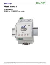
Fig 1. View.
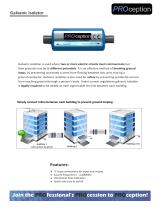
2.3. ISOLATION
ADA-1010 repeater has 2-way or 3-way galvanic isolation and also 1kV= or 3kV= galvanic isolation - depend on version.
Fig 3. Isolation structure.
4
ADA-1010
Power Supply
10 - 30VDC
RS-232 RS-232
Power Supply
10 - 30VDC
RS-232RS-232
3-WAY ISOLATION2-WAY ISOLATION
ADA-1010
REPEATER RS-232
PWRTXRX
RS-232
DSR DTR CTS RTS
OUT
IN
(RS-232)
GND
GND
DTR
DSR
RTS
CTS
TX
RX
(RS-232)
V -
V +
10 – 30
VDC
90mm
53mm
10mm 6mm
Power supply
10-24-30 VDC
RS-232 interface
62mm
RS-232 interface
DB-9F connector

3. INSTALLATION
This chapter will show you haw to properly connect repeater to RS232 interface and power supply and how to use.
In order to minimize effects interference from the environment is recommended:
- use shielded cable – the shield can be connected to the ground on one end,
- arrange signal cables at a distance of not less than 25 cm away from power cables.
3.1. ASSEMBLING
The ADA-1010 enclosure is adapted to assembly on TS-35 (DIN35) rail. To install repeater you should mount device on the rail upper
part of the enclosure then press bottom part to to hear characteristic „Click” sound.
3.2. CONNECTION OF DEVICES WITH RS232 INTERFACE TO 'IN' PORT OF REPEATER
3.2.1. CONNECTION OF DEVICES WITH RS232 PORT - DTE TYPE (COMPUTER)
You need use the RS232 extension cable to connect ADA-1010 to RS232 computer port for example CAB-DB9F/DB9M-S-1,8m
available in our offer. Connection example is shown below.
Fig 3. Example connection to RS-232 computer port.
3.2.2. CONNECTION OF DEVICES WITH RS232 PORT - DCE TYPE (MODEM)
You need use the RS232 cable to connect ADA-1010 to RS232 port (DCE type) eg. CAB-DB9M/DB9M-C-1,8m available in our offer.
Connection example is shown below.
Fig 4. DCE type connection of device with RS232 interface (eg. modem)
5
ADA-1010
RxD - 2
TxD - 3
DTR - 4
DSR - 6
RTS - 7
CTS - 8
PC
SG - 5
RS232 port
DTE/DB-9M
ADA-1010
RS232
terminal
Vss+
Vss-
Power
supply
RS232
DCE/DB-9F
CTS -7
RTS -8
GND -5
Vss-
Vss+
Tx -2
Rx -3
DSR -4
DTR -6
2
3
4
6
7
8
5
CAB-DB 9F/DB9M-S-1,8m
cable
DB-9F
socket
2
3
4
6
7
8
5
DB-9M
plug
CTS
RTS
GND
Tx
Rx
DSR
DTR
TxD - 2
RxD - 3
DSR - 4
DTR - 6
CTS - 7
RTS - 8
Device with RS232
port (DCE type)
eg. Modem
SG -5
RS232 port
DCE/DB-9M
ADA-1010
Vss+
Vss-
Power
Supply
Vss-
Vss+
2
3
4
6
7
8
5
Cable / Adapter
CAB-DB9M/BD9M-C-2m /
ADP-DB9M/DB9M-C
DB-9F
socket
2
3
4
6
7
8
5
DB-9M
plug
RS232 OUT
terminal
RS232 IN
DCE/DB-9F
CTS -7
RTS -8
GND -5
Tx -2
Rx -3
DSR -4
DTR -6
CTS
RTS
GND
Tx
Rx
DSR
DTR

3.3. EXAMPLE CONNECTIONS OF DEVICES TO ADA-1010 REPEATER
Using ADA-1010 it is possible to separate RS232 computer port from the connected device. This type of connection is shown on Fig
5.
Repeater can be used also to extension the RS232 interface for next segments 15 m. Example connection of RS232 interface
extension for 45m is shown on Fig 6.
It is possible to extend RS232 port (eg. Computer) for 300m using ADA-1010 and multicore twisted cable. This connection is shown
on Fig 7.
3.3.1. SEPARATION OF RS232 COMPUTER PORT
Fig 5. Connection for operation as RS232 PC port separator.
3.3.2. RS232 PORT EXTENSION UP TO 45M
Fig 6. Connection for operation as extender RS232 PC port up to 45m. ( 3x15m )
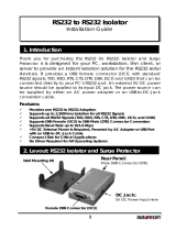
3.3.3. RS232 PORT EXTENSION UP TO 300m
You can extend RS232 port of computer/device to a distance of 300m using ADA-1010 separators. In this case you should make the
wiring as below using multicore cable UTP 4x2x0,5 (connect one wire of pair to signal ground SG).
6
ADA-1010
RxD -2
TxD -3
DTR -4
DSR -6
RTS -7
CTS -8
Device with
RS232 interface
SG -5
RS232
DTE/DB-9M
ADA-1010
RS232OUT
terminal block
Vss+
Vss-
Power
Supply
RS232 IN
DCE/DB-9F
CTS -7
RTS -8
GND -5
Vss-
Vss+
Tx -2
Rx -3
DSR -4
DTR -6
2
3
4
6
7
8
5
CAB-DB 9F/DB9M-S-1,8m Cable
DB-9F
socket
2
3
4
6
7
8
5
DB-9M
plug
Tx
Rx
DSR
DTR
CTS
RTS
GND
RxD -2
TxD -3
DTR -4
DSR -6
RTS -7
CTS -8
PC
SG -5
RS232
DTE/DB-9M
2
3
4
6
7
8
5
DB-9F
socket
ADA-1010
Vss+
Vss-
Tx -2
Rx -3
DSR -4
DTR -6
CTS -7
RTS -8
GND -5
Vss-
Vss+
CAB-DB9M/BD9M-C-15m Cable
2
3
4
6
7
8
5
Extended RS232 port of PC:
Tx,Rx,RTS,CTS,DTR,DSR
2
3
4
6
7
8
5
DB-9M
plug
ADA-1010
Vss+
Vss-
CTS -7
RTS -8
GND -5
Vss-
Vss+
Tx -2
Rx -3
DSR -4
DTR -6
LIYCY 7x0,34 -15m
Cable
2
3
4
6
7
8
5
Tx
Rx
DSR
DTR
CTS
RTS
GND
RxD -2
TxD -3
DTR -4
DSR -6
RTS -7
CTS -8
PC
SG -5
2
3
4
6
7
8
5
Tx
Rx
DSR
DTR
CTS
RTS
GND
CAB-DB 9F/DB9M-S-15m Cable
RS232OUT
terminal block
Power
Supply
RS232 IN
DCE/DB-9F
DB-9M
plug
RS232
DTE/DB-9M
DB-9F
socket
RS232OUT
terminal block
RS232 IN
DCE/DB-9F
Power
Supply
DB-9M
plug
DB-9M
plug

Fig 7. Connection for operation as extender RS232 PC port up to 300m.
7
ADA-1010
ADA-1010
Vss+
Vss-
Tx -2
Rx -3
DSR -4
DTR -6
CTS -7
RTS -8
GND -5
Vss-
Vss+
CAB-DB9M/BD9M-C-1,8m
Cable
2
3
4
6
7
8
5
2
3
4
6
7
8
5
ADA-1010
Vss+
Vss-
CTS -7
RTS -8
GND -5
Vss-
Vss+
Tx -2
Rx -3
DSR -4
DTR -6
UTP 8x2x0,5 Cable
2
3
4
6
7
8
5
Rx
Tx
DTR
DSR
RTS
CTS
GND
RxD -2
TxD -3
DTR -4
DSR -6
RTS -7
CTS -8
PC
SG -5
2
3
4
6
7
8
5
Tx
Rx
DSR
DTR
CTS
RTS
GND
CAB-DB 9F/DB9M-S-1,8m
Cable
RS232OUT
terminal block
Power
Supply
RS232 IN
DCE/DB-9F
DB-9M
plug
RS232
DTE/DB-9M
DB-9F
socket
Extended RS232 port of PC:
Tx,Rx,RTS,CTS,DTR,DSR
RS232OUT
terminal block
RS232 IN
DCE/DB-9F
Power
Supply
DB-9M
plug
DB-9M
plug

3.4. POWER SUPPLY CONNECTION
To connect power supply to repeater you should have DC power supplies (regulated) output voltage from 10 V= to 30V=, min. nominal
power 2W, e.g. HDR-15-24. Power cable from DC power supplies to device can not be longer than 3m. You should connect positive
(+) end of DC power supplies to V+ device terminal and negative (-) end to V- on terminal block. ADA-1010 has protection against
power supply reverse connection and if after connection power supply on front panel will not lighting green led PWR, you should
check correctness of power supply connecting (polarization).
4. ACTIVATION
LEDs on front panel should blinking during data transmission through the separator. Those LEDs indicate:
LED Description
PWR Signalization of Power Supply
TX Signalization of data transmitting via RS-232 (OUT) port
RX Signalization of of data receiving on RS-232 (OUT) port
RTS Signalization of RTS status line on RS-232 (OUT) port
CTS Signalization of CTS status line on RS-232 (OUT) port
DTR Signalization of DTR status line on RS-232 (OUT) port
DSR Signalization of DSR status line on RS-232 (OUT) port
ATTENTION!
At baud rate above 38.4 kbps the LED's Tx, Rx will light weakly during data transmission
5. PIN DESCRIPTION OF DSUB-9F-DCE SOCKET
Pin Signal Description ADA-1010
1 (DCD) Level of receiver signal Not connected
2 (TxD) Transmitted Data Transmitter
3 (RxD) Received Data Receiver
4 (DSR) Data Set Ready Receiver
5 (SG) Signal ground GND
6 (DTR) Data Terminal Ready Transmitter
7 (CTS) Clear To Send Receiver
8 (RTS) Request To Send Transmitter
9 (RI) Call rate Not connected
6. DESCRIPTION OF SCREW TERMINAL BLOCK
Terminal Signal Description ADA-1010
TX (TD) Transmitted Data Transmitter
RX (RD) Received Data Receiver
RTS (RTS) Request To Send Transmitter
CTS (CTS) Clear To Send Receiver
DTR (DTR) Data Terminal Ready Transmitter
DSR (DSR) Data Set Ready Receiver
GND (SG) Signal ground GND
8
ADA-1010

7. VERSIONS
ADA-1010 - -
Order example:
Product Symbol: ADA-1010-23-3
23 – 3-way galvanic isolation 1kV=,
3 – cover without inlets, plug-in screw terminal block,
Galvanic isolation:
1kV=, 2-WAY 2
1kV=, 3-WAY 22
3kV=, 2-WAY 3
3kV=, 3-WAY 33
Terminal & Terminal Cover:
Cover without inlets, screw terminal block 1
Cover with inlets, screw terminal block 2
Cover without inlets, plug-in screw terminal block 3
8. SPECIFICATION
TECHNICAL DATA
Transmission Parameters
Interface RS-232 IN RS-232 OUT
Connector DSUB-9 Female Screw terminal block - max. Ø 2,5mm2
Line length Up to 15m – connection using cable RS232 extender type, baud rate up to 230,4 kbps.
Up to 300m - connection using multicore twisted cable, baud rate up to 56,0 kbps.
Max. number of connected device 2
Maximum baud rate 230,4 kbps
Transmission line DB9F/DB9M multicore cable 9x0,34 shielded or 9-pair twisted cable, UTP 9x2x0,5
(24AWG) shield inside large interferences STP 9x2x0,5 (24AWG).
Transmission type Asynchronous full duplex, half duplex.
Standards EIA-232, CCITT V.24,
Optical Signalization
PWR– green LED power supply,
RX- red LED data receiving through RS232(OUT),
TX- yellow LED data transmission through RS232(OUT),
RTS- yellow LED data transmission through RS232(OUT),
CTS- red LED data receiving through RS232(OUT),
DTR- yellow LED data transmission through RS232(OUT),
DSR- red LED data receiving through RS232(OUT),
Electrical Parameters
Power requirements 10 - 24 – 30 V DC
Power Cable Recommended length of power cable – up to 3m
Power <2W
Protection from reverse power
polarization YES
Galvanic Isolation 1kV or 3kV DC and 2-way or 3-way (between power circuit and signal line RS232 IN)
Optoisolation 3kV (between signal lines RS-232(IN) and RS-232 (OUT))
Electromagnetic compatibility Resistance to disruptions according to the standard PN-EN 55024.
Emission of disruptions according to the standard PN-EN 55022.
Safety requiring According to the PN-EN60950 norm.
Environment Commercial and light industrial.
Environmental Parameters
Operating temperature -30 ÷ 60°C
Humidity 5 ÷ 95% - non-condensing
Storage temperature -40 ÷ 70°C
9
ADA-1010

Casing
Dimensions 53mm x 90mm x 62 mm
Material PC/ABS
Degree of casing protection IP40
Degree of terminal protection IP20
Weight 0.10 kg
According to standard DINAS EN50022, DINAS EN43880
Location during work Free
Mounting method On the rail compliant with DIN35 / TS35 standard.
10
ADA-1010

11
ADA-1010

12
ADA-1010
Dear Customer,
Thank you for purchasing CEL-MAR Company products.
We hope that this user manual helped connect and start up the ADA-1010 separator-repeater. We also wish to inform that we are a
manufacturer of the widest selections of data communications products in the world such as: data transmission converters with
interface RS232, RS485, RS422, USB, Current Loop, Fibre-Optic Converters and Ethernet or Wi-Fi.
Please contact us to tell how you like our products and how we can satisfy you present and future expectation.
CEL-MAR sp.j.
Zakład Informatyki i Elektroniki
Ściegiennego 219C str.
25-116 Kielce, POLAND
Tel....................................................: +48 41 362-12-46
Tel/fax.............................................. : +48 41 361-07-70
Web................................................. : http://www.cel-mar.pl/en
Office............................................... : office@cel-mar.pl
Sales department........................... .: handl[email protected]
Technical information ..................... : support@cel-mar.pl
/