Eaton Power Xpert Meter 1000 Owner's manual
- Category
- Measuring, testing & control
- Type
- Owner's manual

PXM 1000 User Manual
MN150009EN

ii PXM 1000 User Manual MN150009EN October 2018 www.eaton.com
DISCLAIMER OF WARRANTIES AND LIMITATION OF LIABILITY
The information, recommendations, descriptions and safety notations in this document are based on Eaton Corporation”s
(“Eaton”) experience and judgment and may not cover all contingencies. If further information is required, an Eaton sales
office should be consulted. Sale of the product shown in this literature is subject to the terms and conditions outlined in
appropriate Eaton selling policies or other contractual agreement between Eaton and the purchaser.
THERE ARE NO UNDERSTANDINGS, AGREEMENTS, WARRANTIES, EXPRESSED OR IMPLIED, INCLUDING WARRANTIES
OF FITNESS FOR A PARTICULAR PURPOSE OR MERCHANTABILITY, OTHER THAN THOSE SPECIFICALLY SET OUT IN ANY
EXISTING CONTRACT BETWEEN THE PARTIES. ANY SUCH CONTRACT STATES THE ENTIRE OBLIGATION OF EATON. THE
CONTENTS OF THIS DOCUMENT SHALL NOT BECOME PART OF OR MODIFY ANY CONTRACT BETWEEN THE PARTIES.
In no event will Eaton be responsible to the purchaser or user in contract, in tort (including negligence), strict liability or other-
wise for any special, indirect, incidental or consequential damage or loss whatsoever, including but not limited to damage or
loss of use of equipment, plant or power system, cost of capital, loss of power, additional expenses in the use of existing
power facilities, or claims against the purchaser or user by its customers resulting from the use of the information, recom-
mendations and descriptions contained herein. The information contained in this manual is subject to change without notice.

iii
MN150009EN
PXM 1000 User Manual MN150009EN October 2018 www.eaton.com
Contents
1. INTRODUCTION ..................................................1
1.1 Meter Overview ....................................................1
1.2 Areas of Application ................................................2
1.3 Functionality .......................................................2
2. INSTALLATION ...................................................5
2.1 Appearance and Dimensions ..........................................7
2.2 Installation Methods ................................................8
2.3 Wiring ...........................................................9
3. METER DISPLAY AND PARAMETER SETTINGS .......................21
3.1 Display Panel and Keys .............................................21
3.2 Metering Data ....................................................23
3.3 Max/Min Data ....................................................29
3.4 Demand Data ....................................................30
3.5 Harmonic Data ...................................................30
3.6 Expanded I/O Module Data ..........................................32
3.7 Parameter Setting Mode ............................................36
3.8 Page Recovery Function ............................................46
4. DETAILED FUNCTIONS AND SOFTWARE ............................47
4.1. Basic Analog Measurements ........................................47
4.2 Max/Min ........................................................49
4.3 Harmonics and Power Quality Analysis .................................50
4.4 Out-of-limits Alarms ...............................................51
4.5 Data Logging .....................................................56
4.6 Time of Use (TOU) .................................................60
4.7 Power Quality Event Logging and Waveform Capture .....................63
4.8 Seal Function .....................................................69
5. EXTENDED MODULES ...........................................75
5.1 IO Modules ......................................................75
5.2 Ethernet Module ..................................................96
5.3 BACnet Communications ..........................................136
6. COMMUNICATION ..............................................147
6.1 Modbus Protocol Introduction .......................................147
6.2 Communication Format ............................................149
6.3 Data Address Table and Application Details ............................152
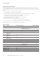
APPENDIX A – TECHNICAL DATA AND SPECIFICATION ..................196
Input Ratings .......................................................196
Accuracy ..........................................................197
Control Power ......................................................197
I/O Options ........................................................198
General Specifications ................................................198

iv
MN150009EN
PXM 1000 User Manual MN150009EN October 2018 www.eaton.com
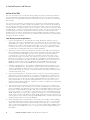
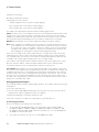
Please read this manual carefully before installation, operation, and maintenance of PXM
1000 meter.
The following symbols in this manual and on PXM 1000 meters are used to provide warning
of danger or risk during the installation and operation of the meters.
Safety Precautions
All safety codes, safety standards, and/or regulations must be strictly observed in the instal-
lation, operation, and maintenance of this device.
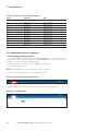
WARNING
The warnings and cautions included as part of the procedural steps in this document
are for personnel safety and protection of equipment from damage. An example of a
typical warning call-out is shown above. This will help to ensure that personnel are
alert to warnings that may appear throughout the document. In addition, cautions are
all upper case and boldfaced as shown below.
WARNING
Completely read and understand the material presented in this document before
attempting installation, operation, or application of the equipment. Only qualified
persons should be permitted to perform any work associated with the equipment. The
wiring, installation and application use instructions presented in this document must
be followed precisely. Failure to do so could cause permanent equipment damage,
bodily injury, or death.
WARNING
Do not attempt to install or perform maintenance on equipment while it is energized.
Death, severe personal injury, or substantial property damage can result from contact
with energized equipment. Always verify that no voltage is present before proceeding
with the task, and always follow generally accepted safety procedures.
Eaton is not liable for the misapplication or misinstallation of its products.
Congratulations!
You have purchased an advanced, versatile, multifunction power meter. This meter can work
as a remote terminal unit (RTU) that contributes to your system”s stability and reliability by
providing real-time power quality monitoring and analysis.
When you open the package, you will find the following items.
QTY
1. PXM 1000 Meter 1
2. Terminal Blocks 3
3. Installation clips 4
4. Rubber Gasket 1
5. Product Disk (Manual, Warranty, Software) 1
6. Additional documentation (Quick Setup Guide, Calibration Certificate) 2
To avoid complications, please read this manual carefully before installation and operation of
the PXM 1000 meter.

1
1. Introduction
PXM 1000 User Manual MN150009EN October 2018 www.eaton.com
1. Introduction
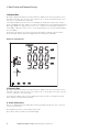
1.1 Meter Overview
Powerful Multifunction Power Meter
The PXM 1000 multifunction digital power meter is designed using modern MCU and DSP
technology. It integrates three-phase energy measurement and display, energy accumula-
tion, power quality analysis, malfunction alarms, data logging, and network communication.
A vivid LCD display with large characters and time-of-use programmable backlight provides a
clear real-time data readout.
Ideal for Electric Automation SCADA Systems
The PXM 1000 meter is the ideal choice for replacing traditional, analog electric meters. In
addition to providing clear real-time readings on the front of the meter, it can also be used as
a remote terminal unit (RTU) for monitoring and controlling for a SCADA system. Users can
access all measurement parameters via the standard RS-485 communication port.
Energy Management
The PXM 1000 meter is able to measure bidirectional, four quadrants kWh and kvarh. It
provides maximum/minimum records for power usage and power demand parameters. All
power and energy parameters can be viewed remotely via software in order to easily moni-
tor various parameters. In addition, measurement tables can be viewed from the free PXM
1000 software.
Remote Power Control
The PXM 1000 is designed for measuring and monitoring power quality parameters. Since
different I/O modules can be added to the meter, this expands the capabilities and provides
a very flexible platform for using the meter as a distributed RTU, for metering, monitoring,
and remote controlling, all in one unit.
Power Quality Analysis
Utilizing digital signal processing (DSP) technology, the PXM 1000 meter provides high
accuracy power quality analysis and supports remote monitoring via the Ethernet module.
The meter continuously updates metering results and allows the users to access the meter
online to monitor parameters such as voltage and current THD, harmonics up to the 31st
(63rd for PXM 1100/1200/1300), voltage crest factor, current K factor, and voltage and current
unbalance factor, etc.
Data Logging
The PXM 1100/1200/1300 meters contain eight megabytes of onboard memory for data
logging and historical trending. Since each meter contains a real-time clock, all events and
logged data will be time stamped.
Time of Use (TOU - PXM 1200)
The user can assign up to four different tariffs (sharp, peak, valley, and normal) to different
time periods within a day according to the billing requirements. The meter will calculate and
accumulate energy to different tariffs, according to the meter’s internal clock timing and TOU
settings.
Power Quality Event Logging
When a power quality event happens, such as voltage sag and swell, etc., the PXM 1300
will record the timestamp and the triggering condition of the event. It can save up to 50,000
power quality events.

2
1. Introduction
PXM 1000 User Manual MN150009EN October 2018 www.eaton.com
Waveform Capture
The PXM 1300 contains another eight megabytes of onboard memory for power quality
event logging and waveform capture. The PXM 1300 can record eight groups of voltage and
current waveforms. It logs at 32 points per cycle. It provides the waveform record of eight
cycles before and after the triggering point. It also supports a configurable triggering condi-
tion.
1.2 Areas of Application
Power Distribution Automation ......Electric Switch Gear and Control Panels
Industry Automation ....................... Building Automation
Energy Management Systems ....... Marine Applications
Renewable Energy
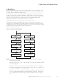
1.3 Functionality
Multifunction
PXM 1000 meters provide powerful data collecting and processing functions. In addition
to measuring various parameters, the meter is able to perform demand metering, harmonic
analysis, max/min statistic recording, out-of-limit alarms, energy accumulation, and data log-
ging.
High Accuracy
Accuracy of Voltage and Current is 0.2%, True-RMS.
Accuracy of Power and Energy is 0.5%, while monitoring all four quadrants.
Compact and Easy to Install
This meter can be installed into a standard ANSI C39.1
(4” Round) or an IEC 92 mm DIN (Square) cut out. With the 51 mm (2”) depth after mount-
ing, the PXM 1000 meter can be installed in a small cabinet. Note that I/O modules add
19.5 mm (0.77in) depth (see Figure 57). Maximum of three modules can be installed.
Mounting clips are used for easy installation and removal.
Easy to Use
All metering data and setting parameters can be accessed using the front panel keys or via
the communication port. Settings parameters are stored in the EEPROM so that content
will be preserved when the meter is powered off.
Multiple Wiring Modes
The PXM 1000 series meter can be used in medium voltage (with PTs), low voltage, three-
phase three-wire, three-phase four-wire, and single-phase systems using different wiring
mode settings.
High Safety, High Reliability
PXM 1000 series meter was designed according to industrial standards. It can run reliably
under high power disturbance conditions. This meter has been fully tested for EMC and
safety compliance in accordance with UL and IEC standards.

3
1. Introduction
PXM 1000 User Manual MN150009EN October 2018 www.eaton.com
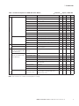
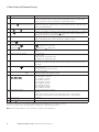
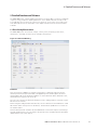
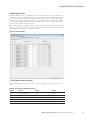
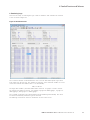
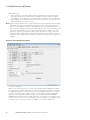
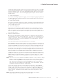
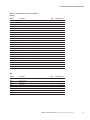
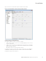
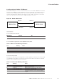
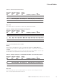
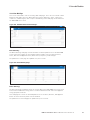
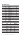
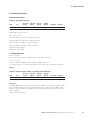
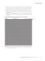
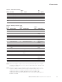
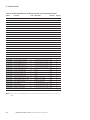
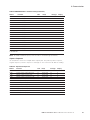
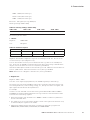
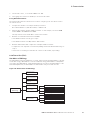
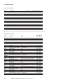
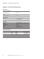
Table 1. Function Comparison of PXM 1000 Series Meters. Function; Option; Blank NA
Category Item Parameters 1000 1100 1200 1300
Metering
Real-time Metering Phase Voltage V1, V2, V3, Vlnavg
Line Voltage V12, V23, V31, Vllavg
Current I1, I2, I3, In, Iavg
Power P1, P2, P3, Psum
Reactive Power Q1, Q2, Q3, Qsum
Apparent Power S1, S2, S3, Ssum
Power Factor PF1, PF2, PF3, PF
Frequency For 800 Hz type, this function is not available
Load Features Load Features
Four Quadrant Powers Four Quadrant Powers
Energy & Demand Energy Ep_imp, Ep_exp, Ep_total, Ep_net
Reactive Energy Eq_imp, Eq_exp, Eq_total, Eq_net
Apparent Energy Es
Demand Dmd_P, Dmd_Q, Dmd_S, Dmd_I1, Dmd_I2, Dmd_I3
TOU
Time of Use Energy/Max Demand TOU, 4 Tariffs, 12 Seasons, 14 Schedules
Daylight Saving Time Two Formats Adjust Month/Day/Hour/Minute; Month/Week/First few
weeks/Hour/Minute
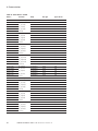
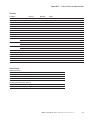
Monitoring
Waveform Capture
(Function not available for 400
Hz and 800 Hz type.)
Voltage and Current
Waveform
Trigger, Manual, DI change, Sag/Dips, Swell, Over
Current
Power Quality
Function not available for 400
Hz and 800 Hz type
Voltage Unbalance Factor U_unbl
Current Unbalance Factor I_unbl
Voltage THD THD_V1,THD_V2,THD_V3, THD_Vavg
Current THD THD_I1, THD_I2, THD_I, THD_Iavg
Individual Harmonics Harmonics 2nd to 31st ( 63rd for PXM
1100/1200/1300)
Voltage Crest Factor Crest Factor
TIF THFF
Current K factor K Factor
Statistics MAX with Time Stamp
MIN with Time Stamp
Each Phase of V & l; Total of P, Q, S,PF & F;
Demand of P,Q & S; Each Phase THD of V & I;
Unbalance factor of V & I
ote:N This manual uses U and V interchangeably for voltage.

4
1. Introduction
PXM 1000 User Manual MN150009EN October 2018 www.eaton.com
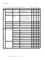
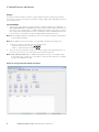
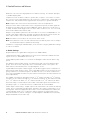
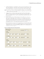
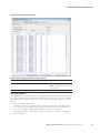
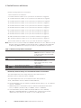
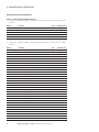
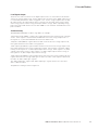
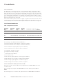
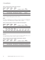
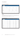
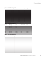
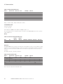
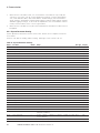
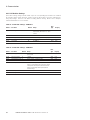
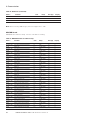
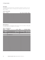
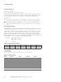
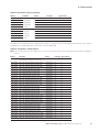
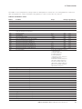
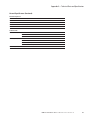
Table 1. Function Comparison of PXM 1000 Series Meters. Function; Option; Blank NA
Category Item Parameters 1000 1100 1200 1300
Others
Alarm Over/Under Limit Alarm V,I,P,Q,S,PF,V_THD & I_THD Each Phase and Total
or Average; Unbalance Factor of V & I; Load Type;
Analog Input of Each Channel
Power Quality Event Logging
(Function not available for 400
Hz and 800 Hz type)
SAG/DIPS,SWELL Voltage
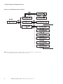
Data Logging Data Logging 1
Data Logging 2
Data Logging 3
F, V1/2/3/lnavg, V12/23/13/lavg, I1/2/3/n/avg,
P1/2/3/sum, Q1/2/3/sum, S1/2/3/sum, PF1/2/3,
PF, U_unbl, I_unbl, Load Type, Ep_imp, Ep_exp, Ep_
total, Ep_net, Eq_imp, Eq_exp, Eq_total, Eq_net,
Es, THD_V1/2/3/avg, THD_I1/2/3/avg, Harmonics
2nd to 63rd, Crest Factor, THFF, K Factor, Sequence
and Phase Angles, DI Counter, AI, AO, Dmd P/Q/S,
Dmd I1/2/3
Onboard Memory Size Memory Bytes 4MB 4MB 8MB
Communication RS485 Port,Half Duplex,
Optical Isolated
Modbus®-RTU Protocol
Time Real Time Clock Year, Month, Date, Hour, Minute, Second
400Hz Type: Only Supports Full-wave (True RMS) Energy, Supports 2nd ~ 15th Individual
Harmonics.
Option Module
I/O Option Switch Status (DI) Digital Input (Wet)
Power Supply for DI 24 Vdc
Relay Output (RO) NO, Form A
Digital Output (DO) Photo-MOS
Pulse Output (PO) By using DO
Analog Input (AI) 0(4)~20mA, 0(1)~5V
Analog Output (AO) 0(4)~20mA, 0(1)~5V
Communication Ethernet Modbus TCP, HTTP, SMTP, SNTP
BACnet/IP BACnet/IP
RS485 Module Modbus-RTU Protocol
RS485 Module Additional Modbus RTU
ote:N This manual uses U and V interchangeably for voltage.
(continued).

5
2. Installation
PXM 1000 User Manual MN150009EN October 2018 www.eaton.com
2. Installation
CAUTION
Installation of the meter must only be performed by qualified personnel, who follow stan-
dard safety precautions through the installation procedures. The personnel should have
appropriate training and experience with high voltage devices. Appropriate safety gloves,
safety glasses, and protective clothing are recommended. Follow NFPA 70E guidelines for
protective equipment.
The meter and its I/O output channels are NOT designed as primary protection devices and
shall NOT be used as primary circuit protection or in an energy-limiting capacity. The meter
and its I/O output channels can only be used as secondary protection. AVOID using the
meter under situations where failure of the meter may cause injury or death. AVOID using
the meter for any application where risk of fire may occur.
WARNING
During normal operation, hazardous voltages will be present. This includes terminals
and any connected current transformers (CTs) and potential transformers (PTs), input
and output (I/O) modules, and their circuits. All primary and secondary circuits can, at
times, produce lethal voltages and currents.
WARNING
Do not attempt to install or perform maintenance on equipment while it is energized.
Death, severe personal injury, or substantial property damage can result from contact
with energized equipment. Always verify that no voltage is present before proceeding
with the task, and always follow generally accepted safety procedures.
Eaton is not liable for the misapplication or misinstallation of its products.
WARNING
All meter terminals should be inaccessible after installation.
DO NOT perform Dielectric (HIPOT) test to any inputs, outputs, or communication ter-
minals. High voltage testing may damage electronic components of the meter.
Applying more than the maximum voltage to the meter and/or its modules will per-
manently damage the product. Please refer to the specifications for all devices before
applying voltages.
When removing the meter for service, use shorting blocks and fuses for voltage leads
and power supply to prevent hazardous voltage conditions or damage to the CTs. CT
grounding is optional.

6
2. Installation
PXM 1000 User Manual MN150009EN October 2018 www.eaton.com
NOTE
The PXM1000 components are maintenance free once properly commissioned. There are
no user serviceable components or features.
Cleaning of the various PXM1000 device housings should only be done with power and
mains disconnected. A clean dry rag can be used to remove dust. No liquids should be used.
CAUTION
If the equipment is used in a manner not specified by the manufacturer, the protection pro-
vided by the equipment may be impaired.
CAUTION
No preventive maintenance or inspection is required for safety. Any maintenance or repair
should be performed by the factory.
WARNING
DISCONNECT DEVICE: The following part is considered the equipment disconnect
device.
A switch or circuit-breaker shall be included in the installation. The switch shall be in
close proximity to the equipment and within easy reach of the operator. The switch
shall be marked as the disconnecting device for the equipment.
The installation method is introduced in this chapter. Please read this chapter carefully
before beginning installation.

7
2. Installation
PXM 1000 User Manual MN150009EN October 2018 www.eaton.com
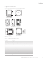
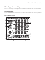
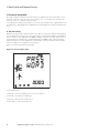
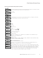
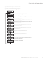
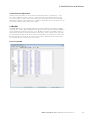
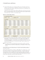
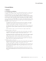
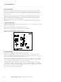
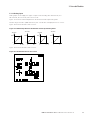
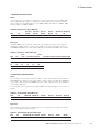
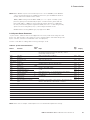
2.1 Appearance and Dimensions
Figure 1. Appearance and Dimensions of the PXM 1000 Meter.
ote:N Unit: mm (inches).
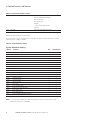
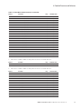
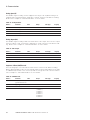
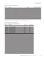
Table 2. Part Name of the PXM 1000 Meter.
Part Name Description
a LCD Display Large, bright white backlight LCD display.
b Front Casing Visible portion (for display and control) after mounting onto a panel.
c Key Four keys are used to interact with the meter.
d Enclosure The PXM 1000 meter enclosure is made of high strength, non-combustible plastic.
e DIN rail Used for Installation - 35 mm rail of the DIN rail meter.
f Voltage Input Terminals Used for voltage input.
g Current Input Terminals Used for current input.
h Power Supply Terminals Used for control power input.
i Communication Terminals Communication output.
j Interface Used to link the remote display unit and the DIN rail meter.
k Installation Clip Used for mounting the meter to the panel.
l Gasket Insert the gasket in between the meter and the cutout to cover up gaps from the round
hole.
HP E V
/
A
PXM 1000
96.00 (3.800)
96.00 (3.800)
Front View of the Display Meter
and Remote Display Unit
Gasket
Gasket
96.00 (3.800)
91.00 (3.583)
35.90 (1.413)
50.70 (1.996)
Side View of the
Display Meter
12.8 (0.504)
91.00 (3.583)
Side View of the
Remote Display Unit
35.90 (1.413)
12.8 (0.504) 14.00
(0.551)
91.00 (3.583)
38.00 (1.496)
7.60 (0.300)
50.70 (1.996)
Side View of the
DIN rail Meter
35.90 (1.413)
Rear View of the
Remote Display Unit
96.00 (3.800)
96.00 (3.800)
Rear View
Installation Clip

8
2. Installation
PXM 1000 User Manual MN150009EN October 2018 www.eaton.com
2.2 Installation Methods
Environmental
Before installation, please check the environment, temperature, and humidity to ensure opti-
mum placement of the PXM 1000 for performance.
Temperature
Operation: -25˚C to 70˚C (-13˚F to 158˚F).
Storage: -40˚C to 85˚C (-40˚F to 185˚F).
Humidity
5% to 95% non-condensing.
The PXM 1000 meter should be installed in a dry and dust free environment. Avoid expos-
ing the meter to excessive heat, radiation, and high electrical noise sources.
Installation Steps
CAUTION
Before drilling or cutting, take the appropriate steps to ensure that drill shavings or metal
chips from drilling and cutting do not fall onto or into any components mounted to the enclo-
sure door or within the enclosure. Drill shavings and metal chips can cause short circuits and
damage to the components within the enclosure.
The PXM 1000 meter can be installed into a standard ANSI C39.1 (4” round) or an IEC 92
mm DIN (square) form.
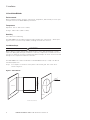
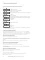
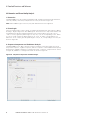
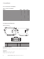
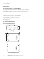
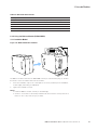
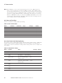
Step 1. Cut a square or round hole on the panel of the switch gear. The cutout size is
shown in Figure 2.
Figure 2. Panel Cutout.
Units: mm (inches).
Panel Panel
Cutout
92.00+0.5
-0.0
+0.5
-0.0
+0.5
-0.0
(3.622)
92.00
(3.622)
101.6
(4.000)
Cutout

9
2. Installation
PXM 1000 User Manual MN150009EN October 2018 www.eaton.com
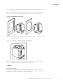
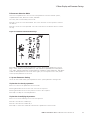
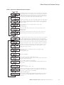
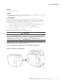
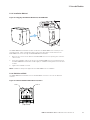
Step 2. Remove the clips from the meter and insert the meter into the square hole from
the front side.
ote:N Optional rubber gasket should be installed on the meter before inserting the meter
into the cut out to cover up gaps from the round hole and to ensure IP ratings.
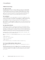
Figure 3. Installing Meter Into Cutout.
Step 3. Install clips on the back side of the meter and secure tightly to ensure the meter is
tightly clamped to the panel.
Figure 4. Use the Clips to Mount the Meter on the Panel.
ote:N The display meter and the remote display unit have the same installation method.
The DIN rail meter is simply installed on a 35 mm DIN rail.
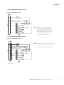
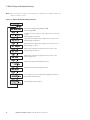
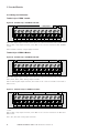
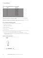
2.3 Wiring
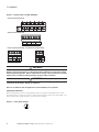
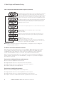
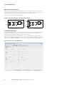
2.3.1 Terminal Strips
There are four terminal strips at the back of the PXM 1000 meter. The three- phase volt-
age and current are represented by 1, 2, and 3 respectively. These numbers have the same
meaning as A, B, and C, or R, S, and T used in other literature.
Panel
Panel
Panel

10
2. Installation
PXM 1000 User Manual MN150009EN October 2018 www.eaton.com
Figure 5. Terminal Strips of PXM 1000 Meter.
WARNING
Do not attempt to install or perform maintenance on equipment while it is energized.
Death, severe personal injury, or substantial property damage can result from contact
with energized equipment. Always verify that no voltage is present before proceeding
with the task, and always follow generally accepted safety procedures.
WARNING
Switch main power off and wait five (5) minutes before making any connection or dis-
connection on the device. Danger of explosion!
Eaton is not liable for the misapplication or misinstallation of its products.
Safety Earth Connection
Before setting up the meter’s wiring, please make sure that the switchgear has an earth
ground terminal. Connect the meter”s earth ground terminal to that of the switchgear.. The
following ground terminal symbol is used in this user manual.
Figure 6. Safety Earth Symbol.
Current Input Terminal Strip
Voltage Input Terminal Strip
Power Supply Terminal Strip - Communication Terminal Strip

11
2. Installation
PXM 1000 User Manual MN150009EN October 2018 www.eaton.com
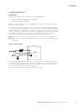
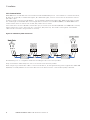
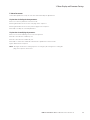
2.3.2 Power Requirement
Control Power
There are two options for the Control Power of the PXM 1000 meter:
1. Standard: 100~415 Vac (50/60 Hz) or 100-300 Vdc.
2. Low Voltage DC Option: 20-60 Vdc.
The correct option must be chosen for the application. Please see the ordering information
appendix for further details.
The meter’s typical power consumption is very low and can be supplied by an independent
source or by the measured load line. If the control power source is not reliable, an uninter-
ruptible power supply (UPS) should be considered. Terminals for the control power supply
are 11, 12, and 13 (L, N, and Ground). A switch or circuit-breaker shall be included in a build-
ing installation. It shall be in close proximity to the equipment, within easy reach of the
operator, and shall be marked as the disconnecting device for the equipment.
ote:N Make sure the control power ground terminal 13, is connected to earth ground.
ote:N Make sure the control power supplied to the meter matches the meter’s power sup-
ply ratings.
Figure 7. Power Supply.
A fuse (typical 1 A/250 Vac) should be used in the auxiliary power supply loop. Terminal
13 must be connected to the ground terminal of the switchgear. In very rare applications
where a power quality problem exists in the power supply, an isolated transformer or EMC
filter should be used in the control power supply loop.
Meter power supply input accepts AWG 14 maximum wire size.
PXM 1000

12
2. Installation
PXM 1000 User Manual MN150009EN October 2018 www.eaton.com
Voltage Input
Maximum input voltage for the PXM 1000 meter shall not exceed 400LN/690LL VAC rms for
three-phase or 400LN VAC rms for single-phase.
A potential transformer (PT) must be used for medium voltage systems. A typical secondary
output for PTs is 100 or 120 V. Note that the PT secondary voltage setting defaults to 220.
Make sure to change this to the appropriate PT setting when setting up the meter. Please
make sure to select an appropriate PT to maintain the measurement accuracy of the meter.
When connecting using the star configuration wiring method, the PT’s primary side rated
voltage should be approximately equal to the phase to neutral voltage of the system to uti-
lize the full range of the PT. When connecting using the delta configuration wiring method,
the PT’s primary side rated voltage should be approximately equal to the line to line voltage
of the system. A fuse (typical 1 A/250 Vac) should be used in the voltage input loop. The
wire for voltage input is AWG 16-12 or
1.3-2.0 mm2.
ote:N In no circumstance should the secondary of the PT be shorted. The secondary of the
PT should be grounded. Please refer to the wiring diagram section for further details.
Current Input
Current transformers (CTs) are required in most engineering applications. A typical current
rating for the secondary side of the CT is 5 A (standard) or 1 A (optional). Please refer to
the ordering information appendix for further details. CTs must be used if the system rated
current is over 5 A. A CT with 0.5% accuracy or better, with a rating over 2.5 VA is recom-
mended to ensure the meter’s accuracy. The wire length between the CTs and meter shall
not exceed the burden rating of the CT to insure accuracy.
Meter Current inputs accept AWG 15-10 or 1.5-2.5 mm2.
WARNING
When power is on, the secondary side of the CT should not be open circuit in any cir-
cumstance. There should not be any fuse or switch in the CT loop. One end of the CT
loop should be connected to Ground.
Vn Connection
Vn is the reference point of the PXM 1000 meter voltage input. Low wire resistance helps
to improve the measurement accuracy. Different system wiring modes require different Vn
connection methods. Please refer to the wiring diagram section for more details.
3-Phase Wiring Diagram
This meter can satisfy almost any kind of three-phase wiring diagrams. Please read this sec-
tion carefully before choosing the optimum wiring configuration for your power system.
The voltage and current input wiring mode can be set separately in the meter parameter set-
ting process. The voltage wiring mode can be set as 3-phase 4-wire Wye
(3 LN), 3-phase 3-wire direct connection (3 LL), 3-phase 3-wire open delta (2 LL), single-
phase 2-wire (1 LN), and single-phase 3-wire (1 LL). The current input wiring mode can be
set as 3 CT, 2 CT, and 1 CT. The voltage mode can be grouped with the current mode as 3
LN-3 CT (3 CT or 2 CT), 3 LL-3 CT, 2 LL-3 CT, 2 LL- 2 CT, 1 LL-2 CT, 1 LN-1 CT.
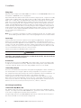
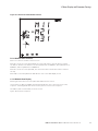
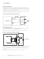
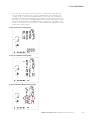
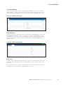
2.3.3 Voltage Input Wiring
3-Phase 4-Wire Wye Mode (3 LN)
The 3-phase 4-wire wye mode is commonly used in low voltage electric distribution power
systems. For voltage lower than 400 LN/690 LL Vac, a power line can be connected directly
to the meter’s voltage input terminal as shown in Figure 8.
For high voltage systems (over 400 LN/690 LL Vac), PTs are required as shown in Figure 9.
The meter should be set to 3 LN for both voltage levels.

13
2. Installation
PXM 1000 User Manual MN150009EN October 2018 www.eaton.com
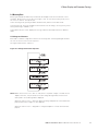
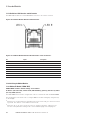
Figure 8. 3 LN Direct Connection.
Figure 9. 3 LN with 3 PT.
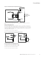
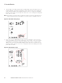
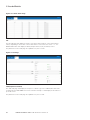
3-Phase 3-Wire Direct Connection Mode (3 LL)
In a 3-phase 3-wire system, power line A, B, and C are connected to V1, V2, and V3 directly.
Leave Vn disconnected. The voltage input mode of the meter should be set to 3 LL.
Figure 10. 3 LL 3-Phase 3-Line Direct Connection.
* 1A fuse typical
PXM 1000
*
PXM 1000
*
PXM 1000
*

14
2. Installation
PXM 1000 User Manual MN150009EN October 2018 www.eaton.com
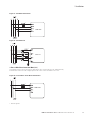
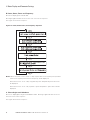
3-Phase 3-Line open Delta Mode (2 LL)
The open delta wiring mode is often used in high voltage systems. V2 and Vn are connected
together in this mode. The voltage input mode of the meter should be set to 2 LL for this
voltage input wiring mode.
Figure 11. 2 LL with 2PTs.
* 1A fuse typical
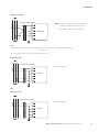
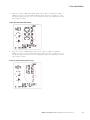
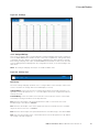
2.3.4 Current Input Wiring
3 CT
The 3CT current wiring configuration can be used when either 3 CTs are connected (as
shown in Figure 12) or 2 CTs are connected (as shown in Figure 13) to the system. In either
case, there is current flowing through all three current terminals.
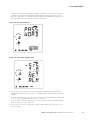
Figure 12. 3 CTs A.
Shorting terminal block not required when used with voltage input current sensors.
LINE
LOAD
V1
V2
V3
7
8
9
A B C
10
1A FUSE
VN
PXM 1000
*
PXM 1000
Shorting Terminal Block
ote:N For meters used with voltage input
current sensors, unused channels
need to be tied to ground as shown
in the figures. If meters are used
with amperage input current sensors,
then the unused channels do not
need to be tied to ground. This note
applies to Figures 12, 14, and 15.

15
2. Installation
PXM 1000 User Manual MN150009EN October 2018 www.eaton.com
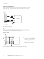
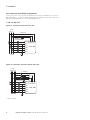
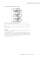
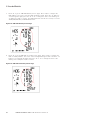
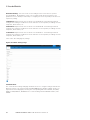
Figure 13. 3 CTs B.
2 CT
For Figures 14 and 15, the meter should be set to the I2 value which is calculated from formula:
i1 + i2 + i3 = 0.
The current input mode of the meter should be set to 2CT .
Figure 14. 2 CT.
1CT
Figure 15. 1 CT.
PXM 1000
Shorting Terminal Block ote:N Shorting terminal block not required when
used with voltage input current sensors.
This applies to all figures on this page
See Note in Figure 12.
PXM 1000
Shorting Terminal Block
See Note in Figure 12.
PXM 1000
Shorting Terminal Block

16
2. Installation
PXM 1000 User Manual MN150009EN October 2018 www.eaton.com
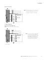
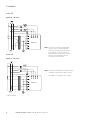
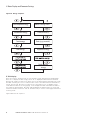
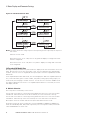
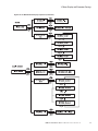
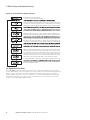
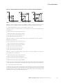
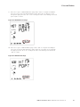
2.3.5 Frequently Used Wiring Configurations
In this section, the most common voltage and current wiring combinations are shown in
different diagrams. In order to display measurement readings correctly, please select the
appropriate wiring diagram for your setup and application.
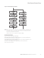
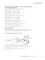
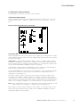
1. 3 LN, 3 CT with 3 CTs.
Figure 16. Three-phase, Three-wire (3LL, 3CT)
Figure 17. Three-phase, Four-wire with PT (3LN, 3CT)
* 1A fuse typical.
VN
V3 V2 V1
Shorting
terminal block
A B C
Line
1 A Fuse
Load
I11
I12
I21
I22
I31
I32
PXM 1000
*
Shorting
terminal block
Load
I11
I12
I21
I22
I31
I32
PXM 1000
A B
Line
1 A Fuse*
C N
VN V3 V2 V1
Page is loading ...
Page is loading ...
Page is loading ...
Page is loading ...
Page is loading ...
Page is loading ...
Page is loading ...
Page is loading ...
Page is loading ...
Page is loading ...
Page is loading ...
Page is loading ...
Page is loading ...
Page is loading ...
Page is loading ...
Page is loading ...
Page is loading ...
Page is loading ...
Page is loading ...
Page is loading ...
Page is loading ...
Page is loading ...
Page is loading ...
Page is loading ...
Page is loading ...
Page is loading ...
Page is loading ...
Page is loading ...
Page is loading ...
Page is loading ...
Page is loading ...
Page is loading ...
Page is loading ...
Page is loading ...
Page is loading ...
Page is loading ...
Page is loading ...
Page is loading ...
Page is loading ...
Page is loading ...
Page is loading ...
Page is loading ...
Page is loading ...
Page is loading ...
Page is loading ...
Page is loading ...
Page is loading ...
Page is loading ...
Page is loading ...
Page is loading ...
Page is loading ...
Page is loading ...
Page is loading ...
Page is loading ...
Page is loading ...
Page is loading ...
Page is loading ...
Page is loading ...
Page is loading ...
Page is loading ...
Page is loading ...
Page is loading ...
Page is loading ...
Page is loading ...
Page is loading ...
Page is loading ...
Page is loading ...
Page is loading ...
Page is loading ...
Page is loading ...
Page is loading ...
Page is loading ...
Page is loading ...
Page is loading ...
Page is loading ...
Page is loading ...
Page is loading ...
Page is loading ...
Page is loading ...
Page is loading ...
Page is loading ...
Page is loading ...
Page is loading ...
Page is loading ...
Page is loading ...
Page is loading ...
Page is loading ...
Page is loading ...
Page is loading ...
Page is loading ...
Page is loading ...
Page is loading ...
Page is loading ...
Page is loading ...
Page is loading ...
Page is loading ...
Page is loading ...
Page is loading ...
Page is loading ...
Page is loading ...
Page is loading ...
Page is loading ...
Page is loading ...
Page is loading ...
Page is loading ...
Page is loading ...
Page is loading ...
Page is loading ...
Page is loading ...
Page is loading ...
Page is loading ...
Page is loading ...
Page is loading ...
Page is loading ...
Page is loading ...
Page is loading ...
Page is loading ...
Page is loading ...
Page is loading ...
Page is loading ...
Page is loading ...
Page is loading ...
Page is loading ...
Page is loading ...
Page is loading ...
Page is loading ...
Page is loading ...
Page is loading ...
Page is loading ...
Page is loading ...
Page is loading ...
Page is loading ...
Page is loading ...
Page is loading ...
Page is loading ...
Page is loading ...
Page is loading ...
Page is loading ...
Page is loading ...
Page is loading ...
Page is loading ...
Page is loading ...
Page is loading ...
Page is loading ...
Page is loading ...
Page is loading ...
Page is loading ...
Page is loading ...
Page is loading ...
Page is loading ...
Page is loading ...
Page is loading ...
Page is loading ...
Page is loading ...
Page is loading ...
Page is loading ...
Page is loading ...
Page is loading ...
Page is loading ...
Page is loading ...
Page is loading ...
Page is loading ...
Page is loading ...
Page is loading ...
Page is loading ...
Page is loading ...
Page is loading ...
Page is loading ...
Page is loading ...
Page is loading ...
Page is loading ...
Page is loading ...
Page is loading ...
Page is loading ...
Page is loading ...
Page is loading ...
Page is loading ...
Page is loading ...
Page is loading ...
Page is loading ...
Page is loading ...
Page is loading ...
Page is loading ...
Page is loading ...
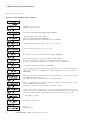
-
 1
1
-
 2
2
-
 3
3
-
 4
4
-
 5
5
-
 6
6
-
 7
7
-
 8
8
-
 9
9
-
 10
10
-
 11
11
-
 12
12
-
 13
13
-
 14
14
-
 15
15
-
 16
16
-
 17
17
-
 18
18
-
 19
19
-
 20
20
-
 21
21
-
 22
22
-
 23
23
-
 24
24
-
 25
25
-
 26
26
-
 27
27
-
 28
28
-
 29
29
-
 30
30
-
 31
31
-
 32
32
-
 33
33
-
 34
34
-
 35
35
-
 36
36
-
 37
37
-
 38
38
-
 39
39
-
 40
40
-
 41
41
-
 42
42
-
 43
43
-
 44
44
-
 45
45
-
 46
46
-
 47
47
-
 48
48
-
 49
49
-
 50
50
-
 51
51
-
 52
52
-
 53
53
-
 54
54
-
 55
55
-
 56
56
-
 57
57
-
 58
58
-
 59
59
-
 60
60
-
 61
61
-
 62
62
-
 63
63
-
 64
64
-
 65
65
-
 66
66
-
 67
67
-
 68
68
-
 69
69
-
 70
70
-
 71
71
-
 72
72
-
 73
73
-
 74
74
-
 75
75
-
 76
76
-
 77
77
-
 78
78
-
 79
79
-
 80
80
-
 81
81
-
 82
82
-
 83
83
-
 84
84
-
 85
85
-
 86
86
-
 87
87
-
 88
88
-
 89
89
-
 90
90
-
 91
91
-
 92
92
-
 93
93
-
 94
94
-
 95
95
-
 96
96
-
 97
97
-
 98
98
-
 99
99
-
 100
100
-
 101
101
-
 102
102
-
 103
103
-
 104
104
-
 105
105
-
 106
106
-
 107
107
-
 108
108
-
 109
109
-
 110
110
-
 111
111
-
 112
112
-
 113
113
-
 114
114
-
 115
115
-
 116
116
-
 117
117
-
 118
118
-
 119
119
-
 120
120
-
 121
121
-
 122
122
-
 123
123
-
 124
124
-
 125
125
-
 126
126
-
 127
127
-
 128
128
-
 129
129
-
 130
130
-
 131
131
-
 132
132
-
 133
133
-
 134
134
-
 135
135
-
 136
136
-
 137
137
-
 138
138
-
 139
139
-
 140
140
-
 141
141
-
 142
142
-
 143
143
-
 144
144
-
 145
145
-
 146
146
-
 147
147
-
 148
148
-
 149
149
-
 150
150
-
 151
151
-
 152
152
-
 153
153
-
 154
154
-
 155
155
-
 156
156
-
 157
157
-
 158
158
-
 159
159
-
 160
160
-
 161
161
-
 162
162
-
 163
163
-
 164
164
-
 165
165
-
 166
166
-
 167
167
-
 168
168
-
 169
169
-
 170
170
-
 171
171
-
 172
172
-
 173
173
-
 174
174
-
 175
175
-
 176
176
-
 177
177
-
 178
178
-
 179
179
-
 180
180
-
 181
181
-
 182
182
-
 183
183
-
 184
184
-
 185
185
-
 186
186
-
 187
187
-
 188
188
-
 189
189
-
 190
190
-
 191
191
-
 192
192
-
 193
193
-
 194
194
-
 195
195
-
 196
196
-
 197
197
-
 198
198
-
 199
199
-
 200
200
-
 201
201
-
 202
202
-
 203
203
-
 204
204


Eaton Power Xpert Meter 1000 Owner's manual
- Category
- Measuring, testing & control
- Type
- Owner's manual
Ask a question and I''ll find the answer in the document
Finding information in a document is now easier with AI
Related papers
-
Eaton PXM1000 dual-port ethernet accessory module Owner's manual
-
Eaton Power Xpert PXM 4000 User and Installation Manual
-
-
-
-
-
-
-
-
Eaton EMA014 Specification
Other documents
-
Lumel NMID30-1 User manual
-
Intermatic ET2725C User manual
-
 Sensitech TagAlert Operating instructions
-
-
 Meters UK Ltd SmartLink EM737 CT User manual
-
 Tense EM-07K User manual
-
 Acrel DL3000-E Operating instructions
-
Intermatic ET2745C User manual
-
-
Acrel 259 User manual


