Page is loading ...

S1616A
Multi-Zone Controller Amplifier
AMPLIFIER MODE
INSTALLATION MANUAL

E L A N H O M E S Y S T E M S S1616A AMPLIFIER MODE
© ELAN Home Systems 2012 | All rights reserved.
Page 1
Preface
Purpose of this Manual
This manual provides step-by-step installation instructions and connection examples, along with basic user information for installation and
ongoing use of the S1616A in Amplifier Mode.. This manual is written for the installer of this equipment.
Organization
The following information is contained in this manual including practices and procedures allowing for the safe installation and operation of
the S1616A used in Amplifier Mode.
Amplifier Mode
Introduction
Provides an introduction to ELAN Home Systems’ S1616A used in Amplifier Mode, along with system features
to include Front and Rear panel controls, indicators and connections, along with a short description of each.
Amplifier Mode
Connections
Provides a description of the S1616A used in Amplifier Mode system connections and direct connections from
the S1616A to other components.
Troubleshooting
Provides troubleshooting tables to help fix common problems that may be encountered when installing the
S1616A used in Amplifier Mode.
IR Command Set
Appendix A provides a list of the IR commands and their functions.

E L A N H O M E S Y S T E M S S1616A AMPLIFIER MODE
© ELAN Home Systems 2012 | All rights reserved.
Page 2
Safety Information
IMPORTANT SAFETY INFORMATION
Read Information — All the safety and operating information should be read before the appliance is operated.
Follow Information — All operating and use information should be followed.
Retain Information — The safety and operating information should be retained for future reference.
Heed Warnings — All warnings on the appliance and in the operating instructions should be heeded.
Wall Mounting — Mounting of this appliance should be done only by an authorized installer.
Ventilation — The appliances should be situated so that their location or position does not interfere with their proper ventilation. These
appliances should never be placed near or over a radiator or heat register. These appliances should not be placed in a built-in installation such as a
bookcase or cabinet that may impede the flow of air through the ventilation openings.
Non-Use Periods — Appliances that are left unattended and unused for long periods of time should be de-energized.
Grounding or Polarization — Do not defeat the safety purpose of the polarized or grounding-type plug. A polarized plug has two blades with
one blade wider than the other blade. A grounding type plug has two blades and a third grounding prong. The polarized wide blade and the third
prong are provided for your safety. If the provided plug does not fit your outlet, consult an electrician for replacement of the obsolete outlet.
Power Cord Protection — Protect the power cord from being walked on or pinched particularly at plugs, convenience receptacles and the
point where they exit from the apparatus.
Water — Do not use the apparatus near water.
Cleaning — Unplug the apparatus from the power outlet before cleaning. Use only a dry cloth to clean the apparatus.
Object and Liquid Entry — Never insert objects of any kind through the openings of these appliances, as they may touch dangerous voltage
points or short-out parts that could result in a fire or electric shock. Care should be taken so that objects do not fall and liquids are not spilled into the
appliance through openings in the enclosure.

E L A N H O M E S Y S T E M S S1616A AMPLIFIER MODE
© ELAN Home Systems 2012 | All rights reserved.
Page 3
Servicing — Do not attempt to service these appliances yourself, as opening or removing covers may expose you to dangerous voltage or other
hazards. Refer all servicing to qualified service personnel.
Damage Requiring Service — These appliances should be serviced by qualified service personnel when:
A power supply connection or a plug has been damaged or
If liquid has been spilled into the appliance or objects have fallen into the appliance or
The appliance has been exposed to water or moisture or
The appliance does not appear to operate normally or exhibits a marked change in performance or
The appliance has been dropped or the enclosure damaged.
Replacement Parts — When replacement parts are required, be sure the service technician has used replacement parts specified by the
manufacturer or that have the same characteristics as the original part. Unauthorized substitutions may result in fire, electric shock, or other hazards.
Safety Check — Upon completion of any service or repairs to this audio product, ask the service technician to perform safety checks to
determine that the audio product is in proper operating condition.
Lightning Storms — Unplug this apparatus during lightning storms or when unused for long periods of time.
Attachments and Accessories — Use only attachments/accessories specified by the manufacturer.
Cart, Stand, Tripod, Bracket or Table — Use only with a cart, stand, tripod, bracket or table specified by the
manufacturer, or sold with the apparatus. When a cart is used, use caution when moving the cart/apparatus combination to
avoid injury from tip over.
Disconnect Device — Where the mains plug or an appliance coupler is used as the disconnect device, the disconnect
device shall remain operable.
NOTE:
This equipment has been tested and found to comply with the limits for a Class B digital device, pursuant to part 15 of the FCC Rules. These limits
are designed to provide reasonable protection against harmful interference in a residential installation.
This equipment generates, uses, and can radiate radio frequency energy and, if not installed and used in accordance with the instructions, may
cause harmful interference to radio communications. However, there is no guarantee that interference will not occur in a particular installation. If this
equipment does cause harmful interference to radio or television reception, which can be determined by turning the equipment off and on, the user is
encouraged to try to correct the interference by one or more of the following measures:
Reorient or relocate the receiving antenna.
Increase the separation between the equipment and receiver.
Connect the equipment into an outlet on a circuit different from that to which the receiver is connected.
Consult the dealer or an experienced radio/TV technician for help.
CAUTION:
Changes or modifications not expressly approved by ELAN Home Systems could void the user’s authority to operate the equipment.

E L A N H O M E S Y S T E M S S1616A AMPLIFIER MODE
© ELAN Home Systems 2012 | All rights reserved.
Page 4
Table of Contents
Preface .................................................................................................. Error! Bookmark not defined.
Purpose of this Manual .............................................................................................................. 1
Organization .............................................................................................................................. 1
Safety Information ........................................................................................................................... 2
Chapter 1: Introduction ........................................................................................6
The ELAN Story ................................................................................... Error! Bookmark not defined.
S1616A Features .............................................................................................................................. 7
S1616A Functions & Indicators ...................................................................................................... 8
Front Panel ................................................................................................................................ 8
S1616A Rear Panel Connections ................................................................................................... 9
Chapter 2: Operation & Settings ........................................................................ 10
Front Panel Controls ..................................................................................................................... 10
Channel Button .............................................................................................................................. 10
Menu Button ................................................................................................................................... 10
Up & Down Arrow Buttons............................................................................................................ 10
Consumer Menu Options .............................................................................................................. 11
Current Volume Settings Display ............................................................................................. 11
Volume Adjustment Menu ........................................................................................................ 11
Fault Menu ............................................................................................................................... 12
Installer Menu Options .................................................................................................................. 13
Amplifier Status Screen ........................................................................................................... 13
Normal Mode .................................................................................................................................. 14
Volume Menu ........................................................................................................................... 14
Input Select Menu .................................................................................................................... 17
Channel Lock Menu ................................................................................................................. 19
ACE Menu ............................................................................................................................... 20
Input View Menu ...................................................................................................................... 21
Output View Menu ................................................................................................................... 22
Utility Sub-Menu ...................................................................................................................... 22
Operating Mode Menu ............................................................................................................. 23
LCD Contrast ........................................................................................................................... 23
LCD Brightness ........................................................................................................................ 24
LCD Sleep Timer ..................................................................................................................... 24
Bus A Input Menu .................................................................................................................... 25
Bus B Input Menu .................................................................................................................... 25
Power Saving Menu ................................................................................................................. 26
Firmware Version ..................................................................................................................... 27
Diagnostics Menu .................................................................................................................... 27

E L A N H O M E S Y S T E M S S1616A AMPLIFIER MODE
© ELAN Home Systems 2012 | All rights reserved.
Page 5
Ambient Temperature .............................................................................................................. 28
Save Dealer Defaults ............................................................................................................... 28
Restore Defaults ...................................................................................................................... 29
ELAN Mode..................................................................................................................................... 31
Absolute Max Volume Menu .................................................................................................... 31
Minimum Turn-On Volume Menu ............................................................................................. 32
Maximum Turn-On Volume Menu ............................................................................................ 32
Address Menu ............................................................................ Error! Bookmark not defined.
Channel Range Menu .............................................................................................................. 33
Chapter 3: Connections ...................................................................................... 34
Line Level Audio Inputs ........................................................................................................... 34
BUS Inputs ............................................................................................................................... 35
BUS Outputs ............................................................................................................................ 36
Speaker Binding Post .............................................................................................................. 37
Triggers .................................................................................................................................... 38
ALL ON Trigger Input ............................................................................................................... 39
+12VDC Trigger Out ................................................................................................................ 40
IR LOOP INPUT/OUTPUT Connections .................................................................................. 41
USB Connector ........................................................................................................................ 42
AC Power Connector ............................................................................................................... 42
Chapter 4: Applications ...................................................................................... 43
Stereo Input with Stereo Output .............................................................................................. 43
Multiple Stereo Inputs .............................................................................................................. 45
Single Stereo Input with Stereo and Mono Output .................................................................. 46
Multiple Bus Inputs with Stereo and Mono Outputs ................................................................. 47
Stand-Alone Stereo Bussing with Multiple Chassis ................................................................. 49
Multi-Room Stereo Zones .......................................................... Error! Bookmark not defined.
S1616A and S128P Sub-Zones W/O Volume Controls ............. Error! Bookmark not defined.
Chapter 5: Troubleshooting ............................................................................... 51
Appendix A: IR Command Set ...................................................................................................... 56
Appendix A: IR Command Set (Continued)................................................................................. 57
Appendix B: Rack Mounting ......................................................................................................... 58
Limited Warranty ........................................................................................................................... 59

E L A N H O M E S Y S T E M S S1616A AMPLIFIER MODE
© ELAN Home Systems 2012 | All rights reserved.
Page 6
Chapter 1: Introduction
The S1616A is the culmination of twenty four years of ELAN experience in the design and
perfection of multi-channel amplification. Designed specifically for the custom installer, the S1616A
used in Amplifier Mode is the perfect solution for multi-room whole-house applications. Providing
cool performance and flexibility, the S1616A Amplifier Mode delivers 16 channels of powerful audio
that can be configured into many combinations to suit any situation that may be encountered in a
whole-house, distributed audio system.
The S1616A utilizes low heat/high efficiency Class D digital technology which features an 8x
oversampling rate and 48 bit signal processing delivering the cleanest and most efficient audio
amplification available. Each channel of the S1616A has a true power rating of 50 watts @ 8 ohms
and 75 watts @ 4 ohms – all channels driven.
Configuration of the S1616A is performed via the front panel interface and includes advanced
features such as max volume output, and min/max turn on levels. An advanced set of IR
commands provides an impressive degree of operability of the S1616A allowing it to be used in
many different control environments.
The ELAN Story
Located in Carlsbad, CA USA, ELAN is a part of The AVC Group, a collection of integration-centric
brands. ELAN has designed innovative multi-room audio/video systems since 1989. ELAN systems
were the first to integrate music, intercom and TV distribution features that used the homeowner’s
stereos, televisions and telephones to create the whole-house entertainment experience. These
systems allow people to move from room to room, controlling centrally located equipment with
ease.
ELAN’s product line includes:
Power Amplifiers
Multi-Zone Pre-Amps
Intelligent Keypads
In-Wall LCD Color Touch Panels
Film Interactive Touchpads
Hand Held Remote Controls
In-Wall and In-Ceiling Speakers
System Controllers
Volume Controls
Telephone-Based Intercom Controllers
Video Switchers
Satellite Radio
Accessories for Home Systems Installation
Outdoor Speakers
Items in Package:
S1616A Power Amplifier
Rack Mount Brackets
Power Cord
Safety Flyer

E L A N H O M E S Y S T E M S S1616A AMPLIFIER MODE
© ELAN Home Systems 2012 | All rights reserved.
Page 7
S1616A Amplifier Mode Features
Class D Digital Technology
Provides clean, transparent audio amplification while greatly reducing power
consumption
50 Watts Per Channel
Easily produces 50W/Ch into an 8 ohm load and 75W/Ch into 4 ohm loads
Automatic Clipping Eliminator (ACE)
This S1616A limiter constantly monitors the amplified output to prevent signal clipping
Automatic Volume Reduction (AVR)
This S1616A limiter constantly monitors the overall output to prevent over-driving the
amplifier
Intelligent Load Monitoring
The S1616A automatically detects load faults and shuts down only the affected channels,
thereby protecting speakers, wiring and the amplifier itself
Multiple Bus Inputs
The S1616A can utilize up to 8 stereo bus inputs to allow sharing a single audio source
between multiple speaker outputs (no jumper wires required)
Buffered Loop Outputs
Every input channel has a buffered loop output that allows the user to easily share audio
sources with other equipment
IR Controllable
Each channel can be independently controlled via IR commands
USB Port
Allows easy in-field firmware updates
Rack Mount Brackets Included
No need to worry about field compatibility
Available in 240 Volt Version
cTUVus, CE
®
, and C-Tick Certified

E L A N H O M E S Y S T E M S S1616A AMPLIFIER MODE
© ELAN Home Systems 2012 | All rights reserved.
Page 8
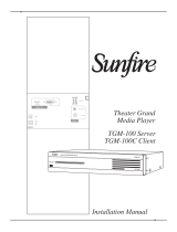
S1616A Functions & Indicators
Front Panel
Figure 0-1: S1616A Front Panel Controls and Display
Item
Function
1
Channel Button
Cycles through information pertaining to each of the 16 audio channels
2
Menu Button
Cycles through various advanced setup features
3
Up Arrow Button
Increments selected menu item
4
Power Indicator
Illuminates when AC power is present and the power switch is on.
5
Down Arrow Button
Decrements selected menu item
6
IR Receive Indicator
Illuminates when the S1616A receives ELAN IR commands

E L A N H O M E S Y S T E M S S1616A AMPLIFIER MODE
© ELAN Home Systems 2012 | All rights reserved.
Page 9
S1616A Amplifier Mode Rear Panel Connections
Figure 0-2
Item
Function
Item
Function
1
Power Switch
Unit master power switch
8
12V Trigger Out
12VDC output when any channel is on
2
Speaker Outputs
Channels 1-16, Five Way Binding Posts
9
IR Input & Output
Used to control the amplifier with IR signals
3
Bus Inputs, A-H
Used to connect multiple speaker outputs to the same audio
source
10
Digital Audio Bus Inputs
Connects S/P-DIF audio source to Bus A or Bus B using
TOSLINK connections
4
Line Level Audio Inputs
Channels 1-16
11
VIA!NET Input & Output
Not used in Amplifier Mode
5
Line Level Audio Outputs
Used for sharing audio sources between chassis
12
USB Mini B Port
For in-field firmware updates
6
12V Trigger Inputs
Used to turn on/off pairs of amplifier channels
13
Fuse Holder
Replace only with T12.5AL250V
7
Trigger All On
Used to turn on all amplifier channels at once
14
Power Cable Connector
IEC type C14
Note: All 3.5mm connectors are mono (two conductors)

E L A N H O M E S Y S T E M S S1616A AMPLIFIER MODE
© ELAN Home Systems 2012 | All rights reserved.
Page 10
Operation & Settings
Front Panel Controls
The S1616A front panel buttons provide control for the initial setup and amplifier status. Any
button press activates the front panel display which shows important system information until the
display times out.
Channel Button
The CHANNEL button toggles through front panel display information pertaining to the individual
16 channels plus an ALL channel option that is available in the Installer Menus.
Menu Button
The menu button allows access to consumer oriented functions as well as options reserved for
installers. In CONSUMER MODE the end user can adjust volume settings on a channel by
channel basis, provided that the channel is UNLOCKED, as well as see current volume/gain and
signal presence information. Installers can access additional setup functions.
In NORMAL MODE, the MENU button toggles through the following menu choices: STATUS,
VOLUME, INPUT SELECT, LOCK, ACE, INPUT VIEW, OUTPUT VIEW, and UTILITY.
Similarly, while in ELAN MODE, the MENU button toggles through the following menu choices:
STATUS, VOLUME, INPUT SELECT, LOCK, ACE, INPUT VIEW, OUTPUT VIEW, ABSOLUTE
MAX VOLUME, MIN TURN ON VOLUME, MAX TURN ON VOLUME, and UTILITY.
These menu items are explained in detail in the following pages as well as how to access installer
menu screens and switch between NORMAL MODE and ELAN MODE.
Up & Down Arrow Buttons
These buttons are used to increment and decrement the currently selected menu item.
Figure 2-1
Front Panel Controls

E L A N H O M E S Y S T E M S S1616A AMPLIFIER MODE
© ELAN Home Systems 2012 | All rights reserved.
Page 11
Consumer Menu Options
Current Volume Settings Display
The first press of the MENU button will bring up the following display showing all 16 channels’
current volume/gain settings and signal presence indicators.
Volume Adjustment Menu
The next press of the MENU button will display the volume screen for the last selected channel as
shown below.
Note: “Channel Locked” - “Output Clipping” - “Input Clipping” and “Fault” status information will
only display if that condition is true. The “IR” indicator will display only when the S1616A is
receiving an ELAN formatted IR signal.
Volume Adjustment Menu (continued)
Use the CHANNEL button to select the desired channel and the up and down arrow buttons to
increment and decrement the gain setting.
A bar graph displays the current channel output (in dBu). The arrowhead indicates a recent output
peak level.
Current trigger status for the selected channel is shown as well as an indication if power saving
mode is engaged (PS). (See Power Saving Menu on page 26.)
The consumer menu does not allow selecting ALL channels at once. This feature is reserved for
installers.
Figure 2-2
Current Volume Settings
Figure 2-3
Volume Adjustment Display

E L A N H O M E S Y S T E M S S1616A AMPLIFIER MODE
© ELAN Home Systems 2012 | All rights reserved.
Page 12
Fault Menu
If a channel is FAULTED the following screen will show in the display.
This shows the faulted channel’s number as well as how many times the channel has faulted due
to high temperature and low impedance combined. It also shows high temperature warnings
separately. The end user can attempt to clear the fault by pressing the UP or DOWN arrows.
If the end user is unable to clear the fault they should contact the dealer for assistance. It is not
necessary to stop using the amplifier in the meantime; continuing to use the amplifier WILL NOT
cause additional damage.
The speaker wires should not be connected to different amplifier channels without first checking for
shorts or low impedance on the speakers.
Figure 2-4
Fault Display

E L A N H O M E S Y S T E M S S1616A AMPLIFIER MODE
© ELAN Home Systems 2012 | All rights reserved.
Page 13
Installer Menu Options
The S1616A Amplifier Mode has two operating modes, Normal and ELAN.
(See Operating Mode Menu on page 23.)
ELAN mode allows the amplifier to respond to S1616A IR commands that can affect its
channels. (See Appendix A for the Command Set.)
NORMAL mode does not allow IR control of the S1616A.
To access the installer menu screens press and hold the MENU button for five seconds until the
following screen shows in the display window. To exit the installer menu screens press and hold
the MENU button again for five seconds or power cycle the amplifier.
Amplifier Status Screen
The Amplifier Status screen allows you to view the current assignments for amplifier gain and
input routing for each of the 16 channels. Press the UP and DOWN arrow buttons to see
information for the next group of four channels. Alternatively, press the CHANNEL button to move
forward one channel at a time.
The top of the screen displays the mode the amplifier is in, either ELAN MODE or NORMAL
MODE, followed by the channel designations of the chassis,
I.E. CH1 – CH16.
CH:1 V:75 IN:1 means that audio input 1 (IN:1) is being amplified at 75% (V:75) and is being
routed to the channel 1 (CH:1) amplified output.
Figure 2-5
Amplifier Status

E L A N H O M E S Y S T E M S S1616A AMPLIFIER MODE
© ELAN Home Systems 2012 | All rights reserved.
Page 14
Normal Mode
Volume Menu
To adjust amplifier output gain on an individual channel, press the MENU button to cycle through
the setting options until the following screen appears:
Use the CHANNEL button to select the desired channel and the UP and DOWN arrow buttons to
increment and decrement the gain setting. Selecting ALL with the CHANNEL button applies
settings to all 16 channels.
Current trigger status for the selected channel is shown as well as an indication if power saving
mode is engaged (PS).
The VOLUME Menu will allow any or all channel's volume to be adjusted from 0% (MUTE) to
100% (maximum gain).
The Factory Default setting for each channel is 75.
The VU (Volume Unit) bar displays real time (current) volume (in dBu) detected at the selected
channel output. The range is from -15 dBu to+30 dBu. The arrowhead indicates a recent output
peak level.
TRIGGER and PS (Power Sense) status are also displayed.
(See Power Saving Menu on page 26, and Trigger information on pages 39-41.)
(Continued on next page)
Figure 2-6
Volume Menu

E L A N H O M E S Y S T E M S S1616A AMPLIFIER MODE
© ELAN Home Systems 2012 | All rights reserved.
Page 15
Volume Menu (Continued)
Trigger ON is the factory default.
The TRIGGER options are:
• On: The selected channel is on (consuming energy) and the trigger jack on the rear panel is
active.
• Off: The selected channel is off (NOT consuming energy) and the trigger jack on the rear panel is
not active.
• On/PS: The selected channel is off (NOT consuming energy) because the selected channel is in
Power Saving Mode even though the trigger jack on the rear panel is active.
When ACE (Automatic Clip Elimination) is active on the selected channel, ACE will be displayed
above Volume %.
(See "ACE Menu" on page 20.)
When AVR (Automatic Volume Reduction) is active, AVR is displayed above Volume %. AVR is
active whenever the amp is being overdriven. When AVR is active, the S1616A turns its volume
down until it is not being overdriven. The S1616A will return to its normal volume setting when it is
no longer being overdriven.
(See the Troubleshooting section for more information on AVR.)
Figure 2-7
Volume Menu with Ace
Figure 2-8
Volume Menu with AVR

E L A N H O M E S Y S T E M S S1616A AMPLIFIER MODE
© ELAN Home Systems 2012 | All rights reserved.
Page 16
Setting System Volume Levels
1. Set each S1616A's channel level to 25%.
2. Raise the volume of all touch panels, touchpads or volume controls to near maximum.
3. Play source program material, such as a CD or a radio station.
4. Have someone step into the room and listen.
5. Enable ACE for all channels. (See ACE Menu on page 20.)
6. On the Volume screen, select the channel that is wired to the speaker where the person is
listening.
7. Slowly adjust Volume Up for this channel until the audio begins to distort, and then drop the
level one or two percentage points.
8. Follow this procedure for all channels to achieve a good balance of sound from the most used
listening position in the zone.
9. Enable or Disable ACE for all applicable channels.
Note: High volume levels can cause clipping and distortion. This can damage the loudspeaker's
components and cause the amplifier to go into protection mode. The protection circuits will reset
when the output signal conditions have returned to normal. Overdriving the amplifier can damage
the amplifier and void the manufacturer's warranty.

E L A N H O M E S Y S T E M S S1616A AMPLIFIER MODE
© ELAN Home Systems 2012 | All rights reserved.
Page 17
Input Select Menu
To change the input used for each output, press the MENU button to cycle through the setting
options until the following screen appears:
Select the channel whose input you wish to change by pressing the CHANNEL button until the
correct channel is displayed. Once the desired output channel is selected pressing the UP and
DOWN arrows will cycle through the following input options:
Input 1 Direct: This is the default, Channel's audio is taken from audio input 1
Input 1 + 2 Mono Direct: Channel's audio is the sum of audio inputs 1 and 2
(Mono)
Input 1 Bus A: Channel's audio is taken from audio input 1 which is Bus A*
Input 1 + 2 Mono Bus A: Channel's audio is the sum of audio inputs 1 and 2
(Mono) which is Bus A*
Input 9 Bus B: Channel's audio is taken from audio input 9 which is Bus B*
Input 9 + 10 Mono Bus B: Channel's audio is the sum of audio inputs 9 and 10
(Mono) which is Bus B*
Input 3 Bus C: Channel's audio is taken from audio input 3 which is Bus C
Input 3 + 4 Mono Bus C: Channel's audio is the sum of audio inputs 3 and 4
(Mono) which is Bus C
Input 11 Bus D: Channel's audio is taken from audio input 11 which is Bus D
Input 11 + 12 Mono Bus D: Channel's audio is the sum of audio inputs 11 and 12
(Mono) which is Bus D
(Continued on next page)
Figure 2-9
Input Select Menu

E L A N H O M E S Y S T E M S S1616A AMPLIFIER MODE
© ELAN Home Systems 2012 | All rights reserved.
Page 18
Input Select Menu (Continued)
Input 5 Bus E: Channel's audio is taken from audio input 5 which is Bus E
Input 5 + 6 Mono Bus E: Channel's audio is the sum of audio inputs 5 and 6 (Mono) which
is Bus E
Input 13 Bus F: Channel's audio is taken from audio input 13 which is Bus F
Input 13 + 14 Mono Bus F: Channel's audio is the sum of audio inputs 13 and 14 (Mono)
which is Bus F
Input 7 Bus G: Channel's audio is taken from audio input 7 which is Bus G
Input 7 + 8 Mono Bus G: Channel's audio is the sum of audio inputs 7 and 8 (Mono) which
is Bus G
Input 15 Bus H: Channel's audio is taken from audio input 15 which is Bus H
Input 15 + 16 Mono Bus H: Channel's audio is the sum of audio inputs 15 and 16 (Mono)
which is Bus H
*Bus A and/or Bus B can be either analog input or digital input. (See pages 25 and 36 for
additional information.)
The following example is with Channel ALL EVEN and Channel ALL ODD selected. Instead of
a single channel's audio being affected like the previous example, all 16 channels are being
affected.
All of the Odd channels (1, 3, 5, 7, 9, 11, 13, 15) are taken from Audio Input 1 which is Bus A
and All of the Even channels (2, 4, 6, 8, 10, 12, 14, 16) are taken from audio input 2 which is
also Bus A.
Figure 2-10
All Channels Selected

E L A N H O M E S Y S T E M S S1616A AMPLIFIER MODE
© ELAN Home Systems 2012 | All rights reserved.
Page 19
Channel Lock Menu
To LOCK or UNLOCK the settings for the channels press the MENU button to cycle through the
setting options until the following screen appears:
This menu allows any or all channels to be locked or unlocked after initial set-up selections have
been determined.
When locked, channel settings cannot be altered even by IR Commands in ELAN mode.
Individual channels 1 - 16 options are LOCKED or UNLOCKED.
When the All channel option is selected the possible status options displayed are MIXED,
LOCKED, or UNLOCKED. MIXED means that some channels are locked and some channels are
not locked.
Press the Channel button to change the channel.
Press the UP and DOWN buttons to LOCK or UNLOCK the selected channel.
Figure 2-11
Lock Menu
/