Page is loading ...

/_ ¢,* i¢_¸ _._
Appliances
i< i i,3Lft_LlIL,
nstallation
instructions
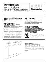
Built-In Dishwasher
If you have questions, call 800.GE.CARES 1800.432.2737} or visit our website at: www.ge.com
BEFORE YOU BEGIN
Read these instructions completely and
carefully.
IMPORTANT.ThedishwasherMUST be installed
to oliow for future removal from the enclosure if service is
required.
,,,A,,_iPORTANT - Observeallgoverningcodesand
ordinances.
• Note to Installer - Be sure to leave these instructions for the
consumer's and local inspector's use,
• Note to Consumer - Keep these instructions with gour
Owner's Manuo! for future reference.
• Skill Level - Installation of this dishwasher requires
basic mechanical, electrical and plumbing skills. Proper
installation is the responsibility of the installer. Product
failui;e due to improper installation is not covered under
the GE Appliance warrontg, See warrantg information.
• Completion Time - 2 to 3 Hours, New installations require
more time than replacement installations.
If gOu received o damaged dishwasher, gou should
immediately contact gout dealer or builder.
Optional Accessories- Seethe 0wner!s Manual for available
custom panel kits,
FOR YOUR SAFETY
Read and observe all CAUTIONS and WARNINGS shown
throughout these instructions, While performing
installations described in this booklet, gloves, safetg glasses
or goggles should be worn.
READ CAREFULLY.
KEEP THESE INSTRUCTIONS.
GSD6000 Series
PDW7000 Series
imagination at work

Installation Preparation
PARTS SUPPLIED
IN INSTALLATION PACKAGE:
[] Two #8-18 × 5/8" Phillips special head screws, to
secure dishwasher to underside of countertop or
sides of cabinets,
[] Junction box cover and #10 he× head screw
[] 2 Side-mounting brackets with four #8 Pan-head
mounting screws for non-wood countertops
{some models)
[] Drain Hose and Hose Clamp
[] Side and top trim pieces (some models)
DrainHose
Junction
Box Cover
Side and Top Trim Pieces on some models
Hose Clamp
Screw Kit
#8 Phillips #10
Special Hex-Head
HeadScrews J-Bo_Screw
SIB"long 1/2" long
SideMount Kit
(some models)
#8 Phillips
Pan-head Screws
3/8" long for
side-mounting
Side- :
Mounting
Brackets
MATERIALS YOU WILL NEED:
[] Ferrule, compression nut and 90° Elbow (3/8"NPT
externet thread on one end, opposite end sized to
fit water supply)
[] Thread seal tape
[] UL Listed wire nuts (3)
Materials For New Installations Only:
[] Air gap for drain hose, if required
[] Waste tee for house plumbing, if applicable
[] Electrical cable or power cord, if appficable
[] Screw tgpe hose clamps
[] Strain relief for electrical Connection
[] Hand shut:off V01ve{recommended}
D Water line-3!8" minimum copper tubing
[] GPF10L drain hose, if needed
TOOLS YOU WILL NEED:
[] Phillips head screwdriver
[] 114" and 5/16" nutdriver
[] 6" Adjustable wrench
[] Level
[] Carpenters square
[] Heasuring tope
[] Safetg gtasses
[] Flashlight
[] Bucket to catch water when flushing the line
[] 15/16" socket (optional for skid removal}
[] Gloves
For New Installations Only:
[] Tubing cutter
[] Drill and appropriate bits
[] Hole sow set
90° Elbow,
Ferrule and
Compression Nut
Waste Tee
Air
Gap
Screwdriver
°,3
"_r--
15116"Socket
Flashlight
Gloves
Hand Thread Wire Nuts 13)
Shut-Off SealTape
Valve
Electrical Cable
!or Power Cord, if applicable)
Hot Water Line
©@
ScrewType
HoseClamps
@
Strain Relief
Optional
10'Drain Hose
GPFZ0L
5116"Nutdriver
i)
6"Adjustable
Wrench
Safety Glasses
Bucket
Hole Saw Set
Level
Tubing Cutter
!
j
Carpenters
Square
MeasuringTape
n Drill and Bits

Installation Preparation
PREPARE DISHWASHER ENCLOSURE
34-1/2"_+ 1//4"
Underside of
Countertop
to Floor
Floor MUST
Figure A
This Wall Area
must be Free
_Pipes or wires
2abinets
Square
and
Plumb
24" Hin:
--q
be Evenwith Plumbing and Electric Service
Room Floor Must Enter Shaded Area
• The rough cabinet opening must be at least 24" deep, 2_"
wide and approximotelg 34-1/2" high from floor to underside
of the countertop.
WARNING
Toreduce the risk ofelectric shock, fire, or injurg to persons,the
installer must ensure that the dishwasher iscompletely enclosed
at the time of installation, ....
(V::
- The dishwasher must be installed so that drain hose is no
more than 10' in length for proper drainage.
• The dishwasher must be fullg enclosed on the top, sides and
back, and must not support and part of the enclosure.
I
Countertop
Dishwasher F
t.........!
28-3/8"
\
n Clearance for Door
opening 2" Hinimum
CLEARANCES:When
installed into a corner,
atlow 2" min. clearance
between dishwasher and
adjacent cabinet, wall or
other appliances. Allow
28_3/8" min. clearance
from the fron; of tile
dishwasher for door
opening. Figure B
Figure B
DRAIN REQUIREMENTS
a Follow local codes and ordinances.
Do not exceed 10' distance to drain.
NOTE: Air gap must be used, if waste tee or disposer
connection is less than 18" above floor, to prevent siphoning. ....
DETERMINE DRAIN METHOD
The type of drain installation depends on the following
questions.
[] Do local codes or ordinances require an air gap?
[] Is waste tee tess than 18" above floor?
If the answer to either question isYES, Method 1 MUST
be used.
o If the answers are NO. either method mad be used.
CABINET PREPARATION
• Drill a t-112" diameter hole in the cabinet wail within
the shaded areas shown in Figure A for the drain hose
connection. The hole should be smooth with no sharp edges.
IMPORTANT: When connecting
drain line to disposer, check to be ]==_
4--- Remove
sure that drain plug has been L__.Z--U_ Drain
removed. DISHWASHERWILL NOT _ Plug
DRAIN 1FPLUG IS LEFTIN PLACE.
L__J
FigureC .... :
MethodI - Air Gapwith Waste Teeor Disposer
Anair gap mustbeusedwhen {eqciiredbg Ioco_codesandordin0nces.:
Theair gap mustbe installed accordingto manufacturer's instructions.
_ _ Drain Has?Hanger
I 2 i ,
3Z'
Hir_
Figure D
_ _ Drain HoseHanger
Method Z- Built-in "High Drain Loop" with Waste Tee or Disposer
Note: Avoidunnecessary service call charges.Alwags be
sure disposer drain plug has been removed before attaching
dishwasher drain hoseto the disposer,

Installation Preparation
PREPARE ELECTRICAL WIRING
FORPERSONALSAFETVI " ' Receptacle : ",
_Ji Remove house fuse or open circuit breaker ' Location --r-k ",,
before beginning installation. Donot use
an extension cord or adapter plug with
this appliance, 8''ill ::
I ,:i
!
Electrical Requirements
• This appliance must be supplied with 120V, 60Hz.. and
connected to on individual properlg grounded branch circuit.
protected bg a 15 or 20 ampere circuit breaker or time delay
fuse.
oWiring must be 2 wire with ground and rated for 75°C {176%}.
• If the electrical supply does not meet the above
requirements, call a licensed electrician before proceeding.
8. /
:::::\ ; ! Hole(Max,} \ t]---
_,-F_ 3'from
! _: :':::: Ca,b',inet
/Receptacle from Wakkx_x_k
V Location
Area Ground-_' i
Figure E Black-" VVhite
Grounding Instructions-Cable Direct
This appliance must be connected to a grounded metal,
permanent wiring sgstem, or an equipment grounding
conductor must be run with the circuit conductors and be
connected to the equipment grounding terminal or lead on the
appliance.
Grounding Instructions-Power Cord Models
This appliance must be grounded. In tile event of o malfunction
or breakdown, grounding will reduce the risk of electric shock
bg providing a path of least resistance for electric current.
This appliance is equipped with o cord having an equipment
grounding conductor and a grounding plug. The plug must
be plugged into an appropriate outlet that is installed and
grounded in accordance with at! local codes end ordinances.
The improper connection of the equipment
grounding conductor can result ina risk
of electric shock. Checkwith a qualified
electrician or service representative if gou
are in doubt that the appliance is propertg
grounded.
For models equipped with power cord: Do not modifg the plug
provided with the appliance; if it will not fit the outlet hove a
proper outlet installed by a qualified technician.
Cabinet Preparation and Wire Routing
• The wiring meg enter the opening from efther side, rear or the
floor within the shaded area.
° Cut o 1-t/2" maximum diameter hole to admit the electrical
cable. Cable direct connections meg pass through the same
hole as the drain hose and hot water line, if convenient. If
cabinet wal! is metal, the hole edge must be €overed With
a bushing.
Note: Power cords with plug must pass through a separate
hole.
Electrical Connection to Dishwasher
Electrical connection is on the right front of dishwasher.
• For cable direct connections the cable must be routed as
shown in Figure E Cable must extend a minimum of 24" from
the rear wall.
° For power cord connections, install a 3-prong grounding tgpe
receptacle in the sink cabinet rear wall. 6" min, or !8" max.
from the opening, 6" to 18" above the floor.
..... --iii //

Installation Instructions
PREPARE HOT WATER LINE
• The line mug enter from either side. rear or floor within the
shaded urea shown in Figure F.
• The line may pass through the some hole as the electrical
cable and drain hose. Or, cut on additional 1-1/2" diameter
hole to accommodate the water fine. If power cord with plug
is used, water line must not pass through power cord hole.
ii Shut-.
_ Valve _.:.:.
HOt: ........... i ::::':
From _
Cabinet !9" FromWall
:: / _L[/_ 2,,From Fioor
Cobinet Foce-_-
FigureF
Water Line Connection
°Turnoff thewater supply.
° Installo hand shut-off valve in on accessible locution, such
us under the sink.(OptionoI,but strongly recommended and
may be required by local codes.}
, Water connection is on the left side of the dishwasher. Install
the hot water inlet line,using no lessthan 3/8" copper tubing.
Routethe line asshown in FigureFand extend forward at
least 197from rear woti....
oAdjust water heater for 120°Fto 150°Ftemperature.
,:Flush water line to clean out debris. :
,The ho:twater supply line pressure must be 20-120 PSI.
:<CAUTION:
:Donot remove wood boseuntil you are readg to install the
dishwasher. Thedishwasher wilt tip aver when the door is opened
if thewood bose isremoved,
STEP 1-PREPARATION :.........
Locate the items in the installation package and set aside for
use in the listed steps:
Screw kit- Steps 5 or 18 and15 :
Side mount kit (some modelsi - Step 12
Junction box cover - Step 5 or 18
Drain lnose and clamp :- Step 7
Trim PieCes {some models) - Step tl
Owner's Hanuot - Steps !9 and 22
Product Samples and/or coupons - Step 22
STEP 2-CHECK DOOR BALANCE
oWith dishwasher on the wood skid, check the door balance
bg opening and closing the door.
• If the door drops when released, increase the spring tension.
If the door rises when released, decrease ttne tension.
Note: Increase or decrease tension
as shown. Adjust both springs
to the some tension setting _'l ""..,
to correct balance. ::::i:_.;;' }:_ ! '\
/::::i/ IY_ t Insert Hook
Increase t /_::_ lOver Bracket
Spring __:, f_t:_ _ /
• ; _::_, : / :
Tens,onA _k_J /
Decreos Correct:
Spring / ,"::::P 7. ...... ./
Tens on V ./ ::: / /::___.
_ _ __' _ incorrect"/" .....,
Figure G
Tip: Ifdoor spring adjustment is necessorg,check door
opening and closing, if door does not openeasilg or falls too
quicklg, check spring cable routing. Thecable is held in ptace
by "shoulders" on the pulleg. Checkto be sure cable has not
slipped over the pulley shoulders.
STEP 3-REMOVE WOOD BASE,
INSTALL LEVELING LEGS
IMPORTANT'oo not kick offwood base! Damage
will occur.
. Hove the dishwasher close to the installation location and lay
it on its back.
• Remove the four leveling legs on the underside of the wood
bose with on adjustable wrench or 15/16" socket,
• Discard base.
Figure H
o Screw leveling legs buck into the dishwasher frame,
uppro×imotelg 1/8" from flume as shown.

Installation Instructions
STEP 4-REMOVE TOEKICK
, Remove the
2 toekick screws
and toekick.
Set aside for use
in Step 21,
F,gure I _.,]_ ]ToekickScrews
STEPS-INSTALL POWER CORD
Skip this step if dishwasher will be direct wired or has a
factorg installed power cord.
In this step gou will need the junction box cover and the
#10 × 1/2" he× head screw from the screw kit set aside in
Step 1,
The power cord and connections must complg with the
National Electrical Code, Section 422 and/or loca! codes and
ordinances, Maximum power cord length is 6 feet. Power Cord
Kit WX09×70910, available for purchase from an authorized GE
Appliance Dealer, meets these requirements.
Junction Box
Cover
Figure J
PowerCord
Wires
0
Dishwasher Wires
• Installstrain relief injunction box bracket.
° insert power cord through strain relief and tighten.
° Plokesure block,white and green dishwasher wires ore
threaded through small hole injunction box bracket.
• Connect power cord white (orribbed} to dishwasher white
wire, black (orsmooth) to dishwasher black wire end ground
to dishwasher greenwire. Use ULlisted wire nuts of
appropriate size.
o Installjunction box cover using #:!0 hex head screw. Besure
wires are not pinched under the cover.
STEP6-INSTALL
90° ELBOW
• Wrap 90° elbow with
thread seal tape.
oTheod 90°elbow into
the water valve.
oDo not over tighten
elbow; water valve
bracket could bend
9(7
or water valve Elbow
fitting could break.
• Position the
end of the elbow
to face the rear
of the dishwasher. Figure K
Front of Dishwasher
Water
_ Valve
Bracket
ff
It-F,I
\
I Hose
_rhread
Seal Tape
STEP7-INSTALL DRAIN HOSE TO
DISHWASHER DRAIN PORT
Skip this step if drain hose has been pro-installed.
In this step gou will need the drain hose and clamp set aside in
Step 1,
, Stand dishwasher upright.
• Place drain hose clamp over Z-3/16" inside diameter end of
drain hose,
Tip: Prevent drain hose damage and possible leaks. Be
careful not to nick or cut the drain hose.
, Push the end of the drain hose over the drain pump outlet
being careful not to disturb the check valve. Refer to Figure L.
o Seat the drain hose end against the hose stops on the pump
outlet.
• Position hose clamp against the front lip of the drain hose
and tighten clamp.
Pump Outlet HoseStops
Note: Drain hose \ "
supplied with dish-
washer is approxi-
matelg 78" long. Ifo
longer hose is
needed, a 220" long
hose (20 feet} mag
be purchased from
an authorized
GE
appliance
dealer. The
!0' long
hose is
part
number _}
GPFIOL
Figure L
6

Installation Instructions
STEP8-POSITION WATER LINE
AND HOUSE WIRING
o Positionwater supply line and housewiring on the floor of
the opening to avoid interference with bose of dishwasher
end components under dishwasher,
House
Wiring
\
Figure N
STEP 9-INSERT DRAIN HOSE
THROUGH CABINET
• Position dishwasher in front of cabinet opening. Insert drain
hose into the hole in cabinet side. tf e power cord is used,
guide the end through o separate hole.
Blanket
Drain
-Hose Length 10'
(If Power
is NOT Used}
Power Cord
(If Used)
Figure N
Tip: Position water line and house wiring on the floor to avoid
interference with base of dishwasher.
STEP IO-SLIDE DISHWASHER
THREE-FOURTHS OF THE WAY
INTO CABINET
DO NOT PUSHAGAINST FRONT PANEL WITH KNEES. DAMAGE
WILL OCCUR,
• Slide dishwasher into the opening a few inches at o _ime,
...d
_Do Not Push Against
Front Door Panel With
Knee, Damage to The
Door Pone! Will Occur.
Figure0
• As you proceed, pull the drain hose through the opening
under the sink. Stop pushing when the dishwasher extends
about 6 inches forward of adjacent Cabinets.
° Hake sure drain hose is not kinked under the dishwasher and
there is no interference with the water line and wiring or any
other component.
STEP 11-INSTALL TRIM PIECES
Skip this step if trim is not supplied with the dishwasher.
o Locate the four trim pieces set aside in Step 1.
o Position the trim pieces so the lips face toward the
dishwasher door.
• Select o long trim piece and press it onto the left side tub
flange. Start with the top edge and press the trim piece
completely onto the tub flange as you move towards the
bottom. Repeat for the right side tub flange trim piece.
• Select one of the short trim pieces, Instal] it on the top tub
flange to the left of the door latch. Select the remaining short
piece of trim end install it on the top tub flange to {he right of
the door latch.
Trim Stri
Figure P

Installation Instructions
h_¸
STEP 12-INSTALL SIDE-MOUNT
BRACKETS (included with
some models)
Skip this step if underside of countertop is wood or
wood-like materia!,
- Install side-mount brackets if underside of countertop is :
granite or similar material that will not accept wood screws,
, Locate the side mount bracket kit set aside in Step I if it was
provided with this model. Otherwise, see Note below.
Note: The brackets are available for purchase when
needed for models not factory equipped with the side mount
kit. Order part GPF65 from gour authorized GEAppliance
Dealer.
• Fasten the left-hand bracket to the left side
of the dishwasher frame. Fasten the
right-hand bracket to the right side of the
dishwasher frame, using the #8 pan-head
screws inctuded with the kit. Refer to
Step 15, Figure U for orientation
and placement.
Side-Mounting
Brackets on
somemodels
STEP 13-PUSH DISHWASHER INTO
FINAL POSITION
Tip: Check tub insulation blanket, if equipped. It should be
positioned so it is not "bunched up" or interfering with door
springs. Check by opening and closing door.
o Push dishwasher into the cabinet. The edges of the
dishwasher door should be behind the cabinet frame and
evenlg atigned with the front face of cabinet doors.
Tip: Avoid unnecessurg service charges. Carefullg open and
close the door to ensure the door panel is not catching or
rubbing on the cabinet frame.
I
f
J
Door
Fits and
Swings
Back
Behind
Cabinet
Frame
Correct
Alignment
Alignment
Figure Q
STEP 14-LEVEL DISHWASHER
IMPORTANT- oishwoshermustbeIevelforproper
dish rack operation and wash performance.
• Place level on door and lower rock track as shown. Check to
make sure that the dishwasher is Jevet left to right and front
to back,
Ch ck
t°-Ba____ift_ t
Figure R
° Level the dishwasher bg adjusting the four leveling legs
individuatlg. Refer to Figure Sbelow.
• If adjustment to the right rear leveling leg is required, loosen
junction bo× bracket screw {through the access hole} and
rotate bracket clockwise. Be sure to tighten screw when
leveling is completed.
Tip: Pull lower rock out, about holfwag. Check to be sure the
rack does not roll forward or back into dishwasher. If the rock
rolls in either direction, the dishwasher must be leveled again.
• If door hits tub, the dishwasher is not installed correctly.
Adjust leveling legs to align door to tub.
""" J Loosen junctiOn:box
...... --. -_- ' bracket screw and
/- \.
,/ ", , rotate bracket outof
__ thewagtoaccessthe
(_I " right rear leveling leg.
Tighten screw when
' leveling operation is
to Adjust ...... completed.
FigureS
8

Installation Instructions
STEP 15-POSITION DISHWASHER, SECURE TO COUNTERTOP OR CABINET
In this step gou will need the 2 Phillips special head screws
from the screw kit set aside in Step 1.The dishwasher must
be secured to the countertop or the cabinet sides. When
the underside of the countertop is wood, use Hethod 1.Use
Hethod 2when the underside of the countertop is made of a
material, such as granite, that will not accept wood screws.
Tip: Prevent door panel and control panel damage, Dishwasher
must be positioned so the front panel and control panel do not
contact the adjacent cabinets or countertop. Mounting screws
must be driven straight and flush. Protruding screw heads
could scratch the door panel or control panel and interfere
with door operation.
Method 1
Secure dishwasher to underside of wood countertop.
, Recheckalignment of the dishwasher in the cabinet. Referto
Steps 13 and 14.Doorpanel and/or control panel must not
hit cabinets or countertop.
• Fastenthe dishwasher to the underside of the countertop
with the 2 Phillipsspecial head screws.Referto FigureT.Hake
certain screws are driven strobht and flush to prevent panel
damage.
Brackets
Wood Countertop
Figure T
Method 2
Secure dishwasher to cabinet sides
•Recheckalignment of the dishwasher in the cabinet. Referto
Steps 1.3and 14.Door panel and/or control panelmust not
hit cabinets or countertop.
• Fastenthe dishwasher to the adjacent cabinets with the
2 Philtipsspecial heed screws provided. Referto Figures U
and V.Hake certain screwsore driven straight and flush to
prevent panel damage.
Side-
Haunting
Brackets
Tub Frame Countertop
Haunting
" ....... Brackets
Bracket
Attachment
Screws
FigUreU (2 Each
Side)
Granite Countertop
/,
Figure V
STEP 16-CONNECT WATER SUPPLY
Connect water suppig line to 90° elbow.
° Slide compression nut, then ferrule over end of water line.
• insert water line into 90° elbow.
° Slide ferrule against elbow and secure with compression nut.
IMPORTANT- Checkto be surethat door spring
doesnot rub or contact the fill hoseor water supply line,Test
bg opening and closing the door.Reroutethe lines if o rubbing
noiseor interference occurs,
Figure W
Door
Spring
90° Elbow
Line

Installation instructions
STEP 17-CONNECT DRAIN LINE
FOLLOW ALL LOCAL CODES AND ORDINANCES. ....
The motded end of the drain hose will fit 5/8" through 1" :
diameter inlet ports on the air gap, waste tee or disposer.
, Determine size of inlet port
• Cut drain hose connector on the marked line, if required, to fit
the inlet port.
Cutting Line
#
IMPORTANT: Do not cut corrugated portion of hose
Figure X
• If a longer drain hose is required and gou did not purchase
drain hose GPFIOL, odd up to 42" length for a total of 120"
110feet} to timefactorg installed hose. Use 5/8" or 7/8" inside
diameter hose and o coupler to connect the two hose ends.
Secure the connection with hose clamps.
Hose Clamp
Figure Y
Hose Clamp
• Securethe drain hoseto the air gap, waste tee or disposer
with c!omps.
Note: TOTAL DRAIN HOSE LENGTH MUST NOT EXCEED10 FEET
FOR PROPERDRAIN OPERATION,
DRAIN LINE INSTALLATION
° Connect drain line to air gap, waste tee or disposer using the"
previously determined method.
Method I - Air gap with waste tee or disposer
Waste Tee Installation
Figure Z
Disposer Installation
Method 2- Built-in "High drain loop" with waste tee or
disposer
Fasten to underside
of cauntertop
-- :-- .... k"" ?......................
]Z'
Min.
l tr--
I r
Fastento underside
of counte_op
............. . .... ! ......
Waste Tee Instatfatian
FigureAA
Disposer Installation
IM PORTANT- Whenconnectingdrainlineto
disposer, check to be sure that the drain f==7=
plug has been removed. DISHWASHER WILL L__ 4--Remove
Drain
NOT DRAIN IF PLUG ISLEFT I I Plug
iN PLACE.
CCT
Tip: Avoid unnecessarg service coil charges. Prior to
connecting drain hose be sure excess hose is not trapped,
kinked or crushed by the dishwasher. Pull excess hose through
the cabinet opening to prevent hose damage and pump out:
issues.
lo

Installation Instructions
STEP 18-CONNECT POWER SUPPLY
If a power cord with plug is already installed proceed to
Step 19.
In this step you will need the junction box cover and the
#!0 hex heed screw from the screw kit set aside in Step 1.
• Secure house wiring to the back of the junction box with a
strain relief.
• Locate the three dishwasher wires, (white, block and green)
with stripped ends. Insert dishwasher wires through the small
hole in the junction box bracket, Use UL listed wire nuts of
appropriate size to connect incoming ground to green, white
to white and block to block.
oInstall the junction box cover using #10 hex heed screw.
Check to be sure that wires ore not pinched under the cover.
PowerCord ___[__
Junction Box Wires
Cover
Ground
White, Blackand Green "'.'_ .... iI / Screw
Dishwasher Wires _'/ .....
Figure BB
If house wiring is not 2-wire with ground, a
ground must be provided by the installer.
When house wiring is aluminum, be sure to
use UL Listed anti-oxidant compound and
aluminum- to-copper connectors
STEP 19-PRETEST CHECK LIST
Review this list after installing your dishwasher to avoid
charges for a service call that is not covered by your
warranty.
[] Check to be sure power is OFF.
D Open door and remove all foam and paper packaging.
[] Locate the Owner's Hanuel set aside in Step 1.
[] Read the Owner's Honuol for operating instructions.
[] Check door opening and closing. If door does not open and
close freely, check for proper routing of spring cable over
pulley, tf door drops or closes when released, adjust spring
tension. See Step 2, Figure G.
[] Checkto be surethat wiring is secure under the dishwasher,
not pinched orin contact with door springsor other
components. SeeStep 10.
[] Checkdoor alignment with tub, If door hits tub, level
dishwasher. SeeSteps 14 and 15,
[] Pulllower rack out, about halfway. Checkto be sureit does
not roll back or forward on the door. If the rock moves,
adjust leveling legs. SeeStep !4.
[] Check door alignment with cabineL If clear hits cabinet,
reposition dishwasher. See Step !5.
[] Check that door spring does not contact water line, fill hose,
wiring or other components. See Step !6.
[]
Verify water supply and drain linesare not kinked or in
contact with other components. Contact with motor or
dishwasher frame could cause noise.
[]
[3
[]
Turn on the sink hot water faucet and verify water
temperature. Incoming water temperature must
be between 120°F and !50°F. A minimum of 120°F
temperature is required for best wash performance. See
"Prepare Hot Water Line," page S.
Add 2 quarts of water to the bottom of the dishwasher to
lubricate the pump sea!.
Turn on water supply_Checkfor leaks.Tighten connections
ifneeded.
[] Removeprotective film if present from the control panel
and door.
!1

Installation Instructions
STEP 20-DISHWASHER WET TEST
[] Turn on power supplg or plug power cord into outlet;
if equipped.
[] Latch door.
[] Push "Rinse Onlg" button.
[] Push Start/Reset pad one time. Dishwasher should start.
[] Check to be sure that water enters the dishwasher. If water
does not enter the dishwasher, check to be sure that water
and power are turned on.
[] Check for leaks under the dishwasher, Ifa leak is found, turn
off power at the breaker, then tighten connections. Restore
power after leak is corrected.
[] Checkfor leaks around the door. A leakaround the door
could be caused bg door rubbing or hitting against
adjacent cabinets, Reposkionthe dishwasher if necessarg.
SeeStep 15.
[] Thedishwasher will drain and turn off about S minutes after
itwas started. Checkdrain lines. If leaksare found, turn off
power at the breaker and correct plumbing as necessarg.
Restorepower after corrections aremade. SeeSteps 7
and !7,
[] Open dishwasher door and make sure most of the water
has drained, tf not, check that disposer plug has been
removed and/or air gap is not plugged, Also Check drain
hose to be sure it is not kinked underneath or behind
dishwasher, See Step 17.
El Press Start/Reset pad once again and run dishwasher
through another "Rinse Onlg" cgcle, Check for leaks and
correct if required.
STEP 21-REPLACE TOEKICK
• Place toekick against the legs of the dishwasher, ' _
Attachment
Screws
FigureCC
° Align the toekick with the bottom edge and make sure it is
against the floor.
• Insert and tighten the two toekick attachment screws, The
toekick should stag in contact with the floor.
Tip: Make sure toekick is against floor to minimize noise,
STEP 22-LITERATURE
° Be sure to leave complete literature package, these
Installation Instructions and product samples and/or coupons
with the consumer.
SPECIFICATIONSSUBJECTTO CHANGE WITHOUT NOTICE
GEConsumer & Industrial
General Electric Company
Louisville, Kentuckg z40225
ge.com
©2006 GeneralEbctric Compang
Pub. No. 31_30210
Dwg, No. 206C1559PlSO
ND 06E-1774 16/061
/