USER'S MANUAL
Revision 1.0
SUPERSERVER
®
2028TP-HTR-SIOM
2028TP-HC0R-SIOM
2028TP-HC1R-SIOM

iii
Preface
Preface
About This Manual
This manual is written for professional system integrators and PC technicians.
It provides information for the installation and use of the SuperServer
2028TP-HTR/HC0R/HC1R-SIOM. Installation and maintainance should be
performed by experienced technicians only.
The SuperServer 2028TP-HTR/HC0R/HC1R-SIOM is a high-end server based
on the SC217HQ+-R2K04BP2 2U rackmount chassis and the dual processor
X10DRT-PS serverboard. All models have four serverboard nodes with six hot-swap
Hard Disk Drives (HDD) each per node.
Manual Organization
Chapter 1: Introduction
The rst chapter provides a checklist of the main components included with the
server system and describes the main features of the X10DRT-PS serverboard and
the SC217HQ+-R2K04BP2 chassis.
Chapter 2: Server Installation
This chapter describes the steps necessary to install the SuperServer
2028TP-HTR/HC0R/HC1R-SIOM into a rack and check out the server conguration
prior to powering up the system. If your server was ordered without processor and
memory components, this chapter will refer you to the appropriate sections of the
manual for their installation.
Chapter 3: System Interface
Refer here for details on the system interface, which includes the functions and
information provided by the control panel on the chassis as well as other LEDs
located throughout the system.
Chapter 4: Standardized Safety Warnings
You should thoroughly familiarize yourself with this chapter for a general overview
of safety precautions that should be followed when installing and servicing the
SuperServer 2028TP-HTR/HC0R/HC1R-SIOM.
Chapter 5: Advanced Serverboard Setup
Chapter 5 provides detailed information on the X10DRT-PS serverboard, including
the locations and functions of connections, headers and jumpers. Refer to
this chapter when adding or removing processors or main memory and when
reconguring the serverboard.
The information in this User’s Manual has been carefully reviewed and is believed to be accurate.
The vendor assumes no responsibility for any inaccuracies that may be contained in this document,
makes no commitment to update or to keep current the information in this manual, or to notify any
person or organization of the updates. Please Note: For the most up-to-date version of this
manual, please see our web site at www.supermicro.com.
Super Micro Computer, Inc. ("Supermicro") reserves the right to make changes to the product
described in this manual at any time and without notice. This product, including software and
documentation, is the property of Supermicro and/or its licensors, and is supplied only under a
license. Any use or reproduction of this product is not allowed, except as expressly permitted by
the terms of said license.
IN NO EVENT WILL SUPERMICRO BE LIABLE FOR DIRECT, INDIRECT, SPECIAL, INCIDENTAL,
SPECULATIVE OR CONSEQUENTIAL DAMAGES ARISING FROM THE USE OR INABILITY TO
USE THIS PRODUCT OR DOCUMENTATION, EVEN IF ADVISED OF THE POSSIBILITY OF
SUCH DAMAGES. IN PARTICULAR, SUPERMICRO SHALL NOT HAVE LIABILITY FOR ANY
HARDWARE, SOFTWARE, OR DATA STORED OR USED WITH THE PRODUCT, INCLUDING THE
COSTS OF REPAIRING, REPLACING, INTEGRATING, INSTALLING OR RECOVERING SUCH
HARDWARE, SOFTWARE, OR DATA.
Any disputes arising between manufacturer and customer shall be governed by the laws of Santa
Clara County in the State of California, USA. The State of California, County of Santa Clara shall
be the exclusive venue for the resolution of any such disputes. Super Micro's total liability for all
claims will not exceed the price paid for the hardware product.
FCC Statement: This equipment has been tested and found to comply with the limits for a Class
A digital device pursuant to Part 15 of the FCC Rules. These limits are designed to provide
reasonable protection against harmful interference when the equipment is operated in a commercial
environment. This equipment generates, uses, and can radiate radio frequency energy and, if not
installed and used in accordance with the manufacturer’s instruction manual, may cause harmful
interference with radio communications. Operation of this equipment in a residential area is likely
to cause harmful interference, in which case you will be required to correct the interference at your
own expense.
California Best Management Practices Regulations for Perchlorate Materials: This Perchlorate
warning applies only to products containing CR (Manganese Dioxide) Lithium coin cells. “Perchlorate
Material-special handling may apply. See www.dtsc.ca.gov/hazardouswaste/perchlorate”
WARNING: Handling of lead solder materials used in this
product may expose you to lead, a chemical known to
the State of California to cause birth defects and other
reproductive harm.
Manual Revision 1.0
Release Date: May 12, 2016
Unless you request and receive written permission from Super Micro Computer, Inc., you may not
copy any part of this document.
Information in this document is subject to change without notice. Other products and companies
referred to herein are trademarks or registered trademarks of their respective companies or mark
holders.
Copyright © 2016 by Super Micro Computer, Inc.
All rights reserved.
Printed in the United States of America

SUPERSERVER 2028TP-HTR/HC0R/HC1R-SIOM USER'S MANUAL
iv
Chapter 6: Advanced Chassis Setup
Refer to Chapter 6 for detailed information on the SC217HQ+-R2K04BP2 server
chassis. You should follow the procedures given in this chapter when installing,
removing or reconguring hard drives and when replacing system power supply
units and cooling fans.
Chapter 7: BIOS
The BIOS chapter includes an introduction to BIOS and provides detailed information
on running the CMOS Setup Utility.
Appendix A: BIOS Error Beep Codes
Appendix B: System Specications
v
SUPERSERVER 2028TP-HTR/HC0R/HC1R-SIOM USER'S MANUAL
Notes

vi
Table of Contents
Chapter 1 Introduction
1-1 Overview ......................................................................................................... 1-1
1-2 Serverboard Features ..................................................................................... 1-2
Processors ...................................................................................................... 1-2
Memory ........................................................................................................... 1-2
SAS ................................................................................................................. 1-2
SATA ................................................................................................................ 1-2
PCI Expansion Slots ....................................................................................... 1-3
I/O Ports .......................................................................................................... 1-3
Graphics Controller ......................................................................................... 1-3
1-3 Server Chassis Features ................................................................................ 1-4
System Power ................................................................................................. 1-4
Front Control Panel ......................................................................................... 1-4
Cooling System ............................................................................................... 1-4
Air Shrouds ..................................................................................................... 1-4
Mounting Rails ................................................................................................ 1-4
1-4 Contacting Supermicro .................................................................................... 1-6
1-5 2U Twin
2
: System Notes ................................................................................. 1-7
Nodes .............................................................................................................. 1-7
System Power ................................................................................................. 1-7
Hard Drive Backplane/Drives .......................................................................... 1-7
Chapter 2 Server Installation
2-1 Overview ......................................................................................................... 2-1
2-2 Unpacking the System .................................................................................... 2-1
2-3 Preparing for Setup ......................................................................................... 2-1
Choosing a Setup Location ............................................................................. 2-2
2-4 Warnings and Precautions .............................................................................. 2-2
Rack Precautions ............................................................................................ 2-2
Server Precautions .......................................................................................... 2-2
Rack Mounting Considerations ....................................................................... 2-3
Ambient Operating Temperature ................................................................ 2-3
Reduced Airow ......................................................................................... 2-3
Mechanical Loading ................................................................................... 2-3
Circuit Overloading ..................................................................................... 2-3
Reliable Ground ......................................................................................... 2-3
2-5 Installing the System into a Rack ................................................................... 2-4
Identifying the Sections of the Rack Rails ...................................................... 2-4
SUPERSERVER 2028TP-HTR/HC0R/HC1R-SIOM USER'S MANUAL
vii
Locking Tabs ................................................................................................... 2-5
Releasing the Inner Rail ................................................................................. 2-5
Installing The Inner Rails on the Chassis ....................................................... 2-6
Installing the Outer Rails on the Rack ............................................................ 2-7
Standard Chassis Installation ......................................................................... 2-8
Chapter 3 System Interface
3-1 Overview ......................................................................................................... 3-1
3-2 Control Panel Button ....................................................................................... 3-2
Power .............................................................................................................. 3-2
UID .................................................................................................................. 3-2
3-3 Control Panel LEDs ........................................................................................ 3-2
Alert ................................................................................................................. 3-2
NIC .................................................................................................................. 3-3
3-4 Hard Drive Carrier LEDs ................................................................................. 3-3
Chapter 4 Standardized Warning Statements for AC Systems
4-1 About Standardized Warning Statements ....................................................... 4-1
Warning Denition ........................................................................................... 4-1
Installation Instructions .................................................................................... 4-4
Circuit Breaker ................................................................................................ 4-5
Power Disconnection Warning ........................................................................ 4-6
Equipment Installation ..................................................................................... 4-8
Restricted Area ................................................................................................ 4-9
Battery Handling ............................................................................................ 4-10
Redundant Power Supplies .......................................................................... 4-12
Backplane Voltage ........................................................................................ 4-13
Comply with Local and National Electrical Codes ........................................ 4-14
Product Disposal ........................................................................................... 4-15
Hot Swap Fan Warning ................................................................................. 4-16
Power Cable and AC Adapter ...................................................................... 4-18
Chapter 5 Advanced Serverboard Setup
5-1 Handling the Serverboard ............................................................................... 5-1
Precautions ..................................................................................................... 5-1
Unpacking ....................................................................................................... 5-1
5-2 Connecting Cables .......................................................................................... 5-2
Connecting Data Cables ................................................................................. 5-2
5-3 Rear I/O Ports ................................................................................................. 5-3
5-4 Processor and Heatsink Installation................................................................ 5-4
Installing a Passive CPU Heatsink ................................................................. 5-7
Removing the Heatsink ................................................................................... 5-8
Table of Contents

viii
5-5 Installing Memory ............................................................................................ 5-9
Memory Support .............................................................................................. 5-9
Memory Support for E5-2600 (v3)-based Serverboards .......................... 5-10
Memory Support for E5-2600 (v4)-based Serverboards ...........................5-11
5-6 Adding PCI Expansion Cards ........................................................................5-11
5-7 Serverboard Details ...................................................................................... 5-12
X10DRT-PS Quick Reference ....................................................................... 5-13
5-8 Connector Denitions .................................................................................... 5-14
5-9 Jumper Settings ............................................................................................ 5-16
Explanation of Jumpers ................................................................................ 5-16
5-10 Onboard Indicators ........................................................................................ 5-18
5-11 PCI-Express and SATA Connections ............................................................ 5-20
5-12 Installing Software ......................................................................................... 5-21
SuperDoctor® 5 ............................................................................................ 5-22
5-13 Onboard Battery ............................................................................................ 5-23
Chapter 6 Advanced Chassis Setup
6-1 Static-Sensitive Devices .................................................................................. 6-1
Precautions ..................................................................................................... 6-1
Unpacking ....................................................................................................... 6-1
6-2 Control Panel .................................................................................................. 6-2
6-3 Chassis Cover ................................................................................................. 6-3
6-4 Air Shrouds ..................................................................................................... 6-4
6-5 Checking the Airow ....................................................................................... 6-5
6-6 System Fans ................................................................................................... 6-5
Optional Fan Congurations ........................................................................... 6-5
6-7 Removing and Installing the Backplane .......................................................... 6-8
Removing the Backplane ................................................................................ 6-8
Installing the Backplane ................................................................................ 6-10
6-8 Installing the Serverboard ..............................................................................6-11
I/O Shield .......................................................................................................6-11
Permanent and Optional Standoffs ................................................................6-11
6-9 Adapter Card Replacement........................................................................... 6-14
Expansion Card/PCI Slot Setup .................................................................... 6-15
Installing the Riser Card ............................................................................... 6-15
6-10 Drive Bay Installation/Removal ..................................................................... 6-17
Accessing the Drive Bays ............................................................................. 6-17
6-11 Power Supply ................................................................................................ 6-20
Power Supply Replacement .......................................................................... 6-20
SUPERSERVER 2028TP-HTR/HC0R/HC1R-SIOM USER'S MANUAL
Chapter 7 BIOS
7-1 Introduction ...................................................................................................... 7-1
Starting BIOS Setup Utility .............................................................................. 7-1
How To Change the Conguration Data ......................................................... 7-1
How to Start the Setup Utility ......................................................................... 7-2
7-2 Main Setup ...................................................................................................... 7-2
7-3 Advanced Setup Congurations...................................................................... 7-4
7-4 Event Logs .................................................................................................... 7-32
7-5 IPMI ............................................................................................................... 7-34
7-6 Security Settings ........................................................................................... 7-36
7-7 Boot Settings ................................................................................................. 7-37
7-8 Save & Exit ................................................................................................... 7-39
Appendix A BIOS Error Beep Codes
Appendix B System Specications
ix
Table of Contents

x
Notes
SUPERSERVER 2028TP-HTR/HC0R/HC1R-SIOM USER'S MANUAL

Chapter 1
Introduction
1-1 Overview
The SuperServer 2028TP-HTR/HC0R/HC1R-SIOM is a high-end server comprised
of two main subsystems: the SC217HQ+-R2K04BP2 2U server chassis and the
X10DRT-PS dual processor serverboard, which reside in four hot-swap nodes.
Please refer to our website for information on operating systems that have been
certied for use with the system (www.supermicro.com).
In addition to the serverboard and chassis, various hardware components have
been included with the SuperServer 2028TP-HTR/HC0R/HC1R-SIOM server, as
listed below:
• Heat Sinks
Four 1U passive CPU heatsinks for rear CPU (SNK-P0047PSM)
Four 1U passive CPU heatsinks w/narrow ILM (SNK-P0057PS)
• Four mylar air shrouds (MCP-310-21703-0B)
• Four 8-cm cooling fans (FAN-0162L4)
• SATA/SAS Backplane
Four HD backplanes (BPN-ADP-6SATA3P/BPN-ADP-S3008L-L6IP/BPN-ADP-
S3108L-H6iRP)
One SAS backplane HDD (BPN-SAS3-217HQ)
Twenty-four hot-swap 2.5" HDD trays (MCP-220-00047-0B)
• Eight riser cards (4x RSC-R1UTP-E16R, 4x RSC-P-6)
• One rackmount rail kit (MCP-290-00053-0N)
Note: For your system to work properly, please follow the links below to download
all necessary drivers/utilities and the user’s manual for your server.
• Supermicro product manuals: http://www.supermicro.com/support/manuals/
• Product drivers and utilities: ftp://ftp.supermicro.com
• Product safety info: http://www.supermicro.com/about/policies/safety_
information.cfm
Chapter 1: Introduction
1-1

1-2 1-3
Chapter 1: IntroductionSUPERSERVER 2028TP-HTR/HC0R/HC1R-SIOM USER'S MANUAL
1-2 Serverboard Features
At the heart of the SuperServer 2028TP-HTR/HC0R/HC1R-SIOM
lies the X10DRT-PS, a dual processor serverboard based on the Intel®
PCH C612 chipset and designed to provide maximum performance. Four of these
serverboards can be mounted in the SC217HQ+-R2K04BP2 chassis.
The sections below cover the main features of the X10DRT-PS serverboard (see
Figure 1-1 for a block diagram of the chipset).
Processors
The X10DRT-PS supports single or dual Intel® Xeon® E5-2600 v3/v4 series
processors (Socket R LGA 2011). Please refer to the serverboard description pages
on our web site for a complete listing of supported processors (www.supermicro.
com).
Memory
The X10DRT-PS has sixteen DIMM slots supporting up to 2 TB of LRDIMM (Load
Reduced DIMM) or 1 TB of RDIMM (Registered DIMM) DDR4-2400/2133/1866 MHz
registered ECC memory. See Chapter 5 for details.
Note: Check the Supermicro website (www.supermicro.com) for the latest memory
support information.
SAS
The 2028TP-HC0R-SIOM includes an LSI 3008 controller to support six SAS3 hard
drives per node. (RAID 0, 1, 5, 6, 10, 50 and 60 supported).
The 2028TP-HC1R-SIOM includes an LSI 3108 controller to support six SAS3 hard
drives per node. (RAID 0, 1, 5, 6, 10, 50 and 60 supported).
The SAS drives are hot-swappable units.
SATA
The 2028TP-HTR-SIOM uses a controller integrated into the PCH C612 chipset to
support six SAS3 hard drives per node. (RAID 0, 1, 5, 6, 10, 50 and 60 supported).
The SATA drives are hot-swappable units.
PCI Expansion Slots
The 2028TP-HTR/HC0R/HC1R-SIOM can support two PCI-E 3.0 expansion cards
in each node. Expansion cards are mounted on riser cards. The RSC-R1UTP-E16R
riser supports a single PCI-E 3.0 x16 card on the right side of the system (when
viewed from the rear) and the RSC-P-6 riser supports one PCI-E 3.0 x16 card on
the left side of the chassis.
I/O Ports
Each of the four X10DRT-PS serverboards in the system include two USB 3.0 ports,
an IPMI LAN port and a VGA port.
In addition, the 2028TP-HTR/HC0R/HC1R-SIOM was designed to accept one of four
different SIOM modules (Supermicro I/O Module) to satisfy the specic I/O functions
required by the system. The various SIOM modules are as follows:
AOC-MGP-i2: two RJ45 (1GbE) ports supported by an Intel® i350-AM2 controller.
AOC-MGP-i4: four RJ45 (1GbE) ports supported by an Intel i350-AM4 controller.
AOC-MTGN-i2S: two SFP+ (10GbE) ports supported by an Intel 82599ES controller.
AOC-MTGN-i4S: four SFP+ (10GbE) ports supported by an Intel XL710-BM1
controller.
Note: For IPMI conguration instructions, please refer to the Embedded BMC
Configuration User's Guide available at http://www.supermicro.com/support/
manuals/.
Graphics Controller
The X10DRT-PS features an integrated ASpeed 2400 BMC with an integrated
VGA/2D graphics controller.

1-4 1-5
Chapter 1: IntroductionSUPERSERVER 2028TP-HTR/HC0R/HC1R-SIOM USER'S MANUAL
1-3 Server Chassis Features
The following is a general outline of the main features of the SC217HQ+ server
chassis.
System Power
The SC217HQ+ chassis includes a redundant, high-efciency 80-plus Platinum
certied power supply rated at 2000 Watts (one active and one backup power supply
module). In the event your power supply fails, replacement is simple and can be
accomplished without tools.
Front Control Panel
The SC217HQ+-R2K04BP2 chassis includes four front panels on the handles of the
chassis which control each of the nodes. Each control panel on the SuperServer
2028TP-HTR/HC0R/HC1R-SIOM provides you with system monitoring and control
for one server node. LEDs indicate system power, HDD activity, network activity,
system overheat and power supply failure. A main power button and a system reset
button are also included.
Cooling System
The SC217HQ+ chassis accepts four system fans, which are powered from the
backplane.
Air Shrouds
The SC217HQ+ chassis includes one mylar air shroud per node that directs the
airow where cooling is needed on each serverboard. Always use the air shroud
included with each serverboard.
Mounting Rails
The SC217HQ+ includes a set of quick-release rails, and can be placed in a rack
for secure storage and use. To setup your rack, follow the step-by-step instructions
included in Chapter 2.
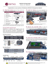
Figure 1-1. Intel PCH C612 Chipset:
System Block Diagram
Note: This is a general block diagram and may not exactly repre-
sent the features on your serverboard. See the previous pages for
the actual specications of your serverboard. This block diagram is
intended for your reference only.
SPI
LAN3
RGRMII
Debug Card
FRONT PANEL
SYSTEM POWER
CTRL
FAN SPEED
PCI-E X1 G2
USB 2.0
PCH
6.0 Gb/S
USB 2.0
LPC
#1
#0
#5
#4
RTL8211E
-VB-CG
#3
#2
RJ45
SPI
Temp Sensor
EMC1402-1 *2 at di SMBUS
TPM HEADER
USB 3.0
USB
AST2400
BMC
RMII/NCSI
COM1
Connector
VGA CONN
BMC Boot Flash
DDR3
DDR4
P1
P1
P0
P0
#2-1
DDR4
#1-4
#1-3
#1-2
#1-1
QPI
9.6G
DMI2
PCI-E X8 G3
#1-5
#1-6
DDR4
QPI
9.6G
#1
SIOM
PCI-E X16
SXB1
SLOT1
SLOT2
PCI-E X8 mini PCI-E
PCI-E X16 G3
PCI-E X16 G3
#1 #2 #3
#3
#1-7
#1-8
#2-2
#2-3
#2-4
#2-5
#2-6
#2-7
#2-8
#6
#7
#8
#9
SXB2
Go go adapter card.
BIOS
SPI
MUX
DDR4
2UPC1UPC
#2
DMI2
DMI2
SATA

1-6 1-7
Chapter 1: IntroductionSUPERSERVER 2028TP-HTR/HC0R/HC1R-SIOM USER'S MANUAL
1-4 Contacting Supermicro
Headquarters
Address: Super Micro Computer, Inc.
980 Rock Ave.
San Jose, CA 95131 U.S.A.
Tel: +1 (408) 503-8000
Fax: +1 (408) 503-8008
Email: [email protected] (General Information)
[email protected] (Technical Support)
Website: www.supermicro.com
Europe
Address: Super Micro Computer B.V.
Het Sterrenbeeld 28, 5215 ML
's-Hertogenbosch, The Netherlands
Tel: +31 (0) 73-6400390
Fax: +31 (0) 73-6416525
Email: [email protected] (General Information)
[email protected] (Technical Support)
[email protected] (Customer Support)
Website: www.supermicro.nl
Asia-Pacic
Address: Super Micro Computer, Inc.
3F, No. 150, Jian 1st Rd.
Zhonghe Dist., New Taipei City 235
Taiwan (R.O.C)
Tel: +886-(2) 8226-3990
Fax: +886-(2) 8226-3992
Email: [email protected]
Website: www.supermicro.com.tw
1-5 2U Twin
2
: System Notes
As a 2U Twin
2
conguration, the SuperServer 2028TP-HTR/HC0R/HC1R-SIOM is
a unique server system. With four system boards incorporated into a single chassis
acting as four separate nodes, there are several points you should keep in mind.
Nodes
Each of the four serverboards act as a separate node in the system. As independent
nodes, each may be powered off and on without affecting the others. In addition,
each node is a hot-swappable unit that may be removed from the rear of the chassis.
The nodes are connected to the server backplane by means of an adapter card.
Note: A guide pin is located between the upper and lower nodes on the inner chassis
wall. This guide pin also acts as a “stop” when a node is fully installed. If too much
force is used when inserting a node this pin may break off. Take care to slowly slide
a node in until you hear the “click” of the locking tab seating itself.
System Power
Dual 2000 Watt power supplies are used to provide the power for all four
serverboards. Each serverboard however, can be shut down independently of the
other with the power button on its own control panel.
Hard Drive Backplane/Drives
As a system, the SuperServer 2028TP-HTR/HC0R/HC1R-SIOM supports the use
of 24 hard drives (SAS or SATA). A single backplane works to apply system-based
control for power and fan speed functions, yet at the same time logically connects
a set of six hard drives to each of the four nodes. Consequently, RAID setup is
limited to a six-drive scheme (RAID cannot be spread across all 24 drives). See
the Drive Bay Installation/Removal section in Chapter 6 for the logical hard drive
and node conguration.

1-8
SUPERSERVER 2028TP-HTR/HC0R/HC1R-SIOM USER'S MANUAL
Notes

Chapter 2: Server Installation
2-1
Chapter 2
Server Installation
2-1 Overview
This chapter provides a quick setup checklist to get your SuperServer
2028TP-HTR/HC0R/HC1R-SIOM up and running. Following these steps in the order
given should enable you to have the system operational within a minimum amount
of time. This quick setup assumes that your system has come to you with the
processors and memory preinstalled. If your system is not already fully integrated
with a serverboard, processors, system memory etc., please turn to the chapter or
section noted in each step for details on installing specic components.
2-2 Unpacking the System
You should inspect the box the 2028TP-HTR/HC0R/HC1R-SIOM server was
shipped in and note if it was damaged in any way. If the server itself shows damage
you should le a damage claim with the carrier who delivered it.
Decide on a suitable location for the rack unit that will hold the
2028TP-HTR/HC0R/HC1R-SIOM server. It should be situated in a clean, dust-
free area that is well ventilated. Avoid areas where heat, electrical noise and
electromagnetic elds are generated. You will also need it placed near a grounded
power outlet. Read the Rack and Server Precautions in the next section.
2-3 Preparing for Setup
The box the SuperServer 2028TP-HTR/HC0R/HC1R-SIOM was shipped in should
include two sets of rail assemblies, two rail mounting brackets and the mounting
screws you will need to install the system into the rack. Follow the steps in the
order given to complete the installation process in a minimum amount of time.
Please read this section in its entirety before you begin the installation procedure
outlined in the sections that follow.

Chapter 2: Server Installation
2-32-2
SUPERSERVER 2028TP-HTR/HC0R/HC1R-SIOM USER'S MANUAL
Choosing a Setup Location
• Leave enough clearance in front of the rack to enable you to open the front door
completely (~25 inches) and approximately 30 inches of clearance in the back
of the rack to allow for sufcient airow and ease in servicing.
• This product is for installation only in a Restricted Access Location (dedicated
equipment rooms, service closets and the like).
• This product is not suitable for use with visual display work place devices
acccording to §2 of the the German Ordinance for Work with Visual Display Units.
2-4 Warnings and Precautions
Rack Precautions
• Ensure that the leveling jacks on the bottom of the rack are fully extended to
the oor with the full weight of the rack resting on them.
• In single rack installation, stabilizers should be attached to the rack. In multiple
rack installations, the racks should be coupled together.
• Always make sure the rack is stable before extending a component from the
rack.
• You should extend only one component at a time - extending two or more
simultaneously may cause the rack to become unstable.
Server Precautions
• Review the electrical and general safety precautions in Chapter 4.
• Determine the placement of each component in the rack before you install the
rails.
• Install the heaviest server components on the bottom of the rack rst, and then
work up.
• Use a regulating uninterruptible power supply (UPS) to protect the server from
power surges, voltage spikes and to keep your system operating in case of a
power failure.
• Allow any hot plug drives and power supply modules to cool before touching
them.
• Always keep the rack's front door and all panels and components on the servers
closed when not servicing to maintain proper cooling.
Rack Mounting Considerations
Ambient Operating Temperature
If installed in a closed or multi-unit rack assembly, the ambient operating
temperature of the rack environment may be greater than the ambient temperature
of the room. Therefore, consideration should be given to installing the equipment
in an environment compatible with the manufacturer’s maximum rated ambient
temperature (Tmra).
Reduced Airow
Equipment should be mounted into a rack so that the amount of airow required
for safe operation is not compromised.
Mechanical Loading
Equipment should be mounted into a rack so that a hazardous condition does not
arise due to uneven mechanical loading.
Circuit Overloading
Consideration should be given to the connection of the equipment to the power
supply circuitry and the effect that any possible overloading of circuits might have
on overcurrent protection and power supply wiring. Appropriate consideration of
equipment nameplate ratings should be used when addressing this concern.
Reliable Ground
A reliable ground must be maintained at all times. To ensure this, the rack
itself should be grounded. Particular attention should be given to power supply
connections other than the direct connections to the branch circuit (i.e. the use of
power strips, etc.).
Warning! To prevent bodily injury when mounting or servicing this unit in a
rack, you must take special precautions to ensure that the system remains
stable. The following guidelines are provided to ensure your safety:
• This unit should be mounted at the bottom of the rack if it is the only unit in
the rack.
• When mounting this unit in a partially lled rack, load the rack from the bottom
to the top with the heaviest component at the bottom of the rack.
• If the rack is provided with stabilizing devices, install the stabilizers before
mounting or servicing the unit in the rack.

Chapter 2: Server Installation
2-52-4
SUPERSERVER 2028TP-HTR/HC0R/HC1R-SIOM USER'S MANUAL
2-5 Installing the System into a Rack
This section provides information on installing the 2028TP-HTR/HC0R/HC1R-SIOM
into a rack unit with the rails provided. There are a variety of rack units on the market,
which may mean that the assembly procedure will differ slightly from the instructions
provided. You should also refer to the installation instructions that came with the
rack unit you are using. Note: This rail will t a rack between 26.5" and 36.4" deep.
Identifying the Sections of the Rack Rails
The chassis package includes two rail assemblies in the rack mounting kit. Each
assembly consists of three sections: An inner chassis rail which secures directly to
the chassis, an outer rail that secures to the rack, and a middle rail which extends
from the outer rail (see Figure 2-1). These assemblies are specically designed for
the left and right side of the chassis.
Figure 2-1. Identifying the Outer Rail, Middle Rail and Inner Rails
(Left Rail Assembly Shown)
Inner Rail
Rail Assembly
(Shown with Rails
Retracted)
This Side Faces
Outward
Locking Tab
Middle Rail
Outer Rail
Figure 2-2. Extending and Releasing the Inner Rail
Locking Tabs
Each inner rail has a locking tab. This tab locks the chassis into place when installed
and pushed fully into the rack. These tabs also lock the chassis in place when fully
extended from the rack. This prevents the server from coming completely out of
the rack when when the chassis is pulled out for servicing.
Releasing the Inner Rail
Use the procedure below to release the inner rails from the outer rails.
Releasing Inner Rail from the Outer Rails (Figure 2-2)
1. Identify the left and right outer rail assemblies as described in section 2-5.
2. Pull the inner rail out of the outer rail until it is fully extended as illustrated
below.
3. Press the locking tab down to release the inner rail.
4. Pull the inner rail all the way out.
5. Repeat steps 1-3 for the second outer rail.
1
2
1
1
1
3
1
4
Warning: do not pick up the server with the front handles. They are
designed to pull the system from a rack only.

Chapter 2: Server Installation
2-72-6
SUPERSERVER 2028TP-HTR/HC0R/HC1R-SIOM USER'S MANUAL
Figure 2-3. Installing the Inner Rails
Installing The Inner Rails on the Chassis
To install the inner rails, use the procedure below.
Installing the Inner Rails (Figures 2-3 and 2-4)
1. Conrm that the left and right inner rails have been correctly identied.
2. Place the inner rail rmly against the side of the chassis, aligning the hooks
on the side of the chassis with the holes in the inner rail.
3. Slide the inner rail forward toward the front of the chassis until the rail clicks
into the locked position, which secures the inner rail to the chassis.
4. Secure the inner rail to the chassis with the screws provided.
5. Repeat steps 1 through 4 above for the other inner rail.
Figure 2-5. Extending and Releasing the Outer Rails
1
1
1
2
1
3
1
4
21D01
L-min=676.00(26.61")(outer rail)
Installing the Outer Rails on the Rack
Use the procedure below to install the outer rails onto the rack.
Installing the Outer Rails (Figure 2-5)
1. Press upward on the locking tab at the rear end of the middle rail.
2. Push the middle rail back into the outer rail.
3. Hang the hooks of the front of the outer rail onto the slots on the front of
the rack. If necessary, use screws to secure the outer rails to the rack, as
illustrated above.
4. Pull out the rear of the outer rail, adjusting the length until it ts within the
posts of the rack.
5. Hang the hooks of the rear portion of the outer rail onto the slots on the rear
of the rack. If necessary, use screws to secure the rear of the outer rail to the
rear of the rack.
6. Repeat steps 1-5 for the remaining outer rail.
Slide rail mounted equipment is not to be used as a shelf or a work space.
Stability hazard. The rack stabilizing mechanism must be in place, or the
rack must be bolted to the oor before you slide the unit out for servicing.
Failure to stabilize the rack can cause the rack to tip over.
Figure 2-4. Inner Rails Installed on the Chassis
1
3
1
4
1
4
1
2
Inner Rails

2-8
SUPERSERVER 2028TP-HTR/HC0R/HC1R-SIOM USER'S MANUAL
Figure 2-6. Installing into a Rack
Ball-Bearing
Shuttle
Standard Chassis Installation
Installing the Chassis into a Rack (Figure 2-6)
1. Conrm that the inner rails are properly installed on the chassis.
2. Conrm that the outer rails are correctly installed on the rack.
3. Pull the middle rail out from the front of the outer rail and make sure that the
ball-bearing shuttle is at the front locking position of the middle rail.
4. Align the chassis inner rails with the front of the middle rails.
5. Slide the inner rails on the chassis into the middle rails, keeping the pressure
even on both sides, until the locking tab of the inner rail clicks into the front of
the middle rail, locking the chassis into the fully extended position.
6. Depress the locking tabs of both sides at the same time and push the chassis
all the way into the rear of the rack.
7. If necessary for security purposes, use screws to secure the chassis handles
to the front of the rack.
Note: The gure below is for illustrative purposes only. Always install servers to
the bottom of the rack rst.

Chapter 3: System Interface
3-1
Chapter 3
System Interface
3-1 Overview
There are several LEDs on the control panel and on the drive carriers to keep you
constantly informed of the overall status of the system. SC217HQ+ models include
four front panels on the handles of the chassis which control each of the systems.
This chapter explains the meanings of all LED indicators and the appropriate
response you may need to take.
Figure 3-1. Control Panel

SUPERSERVER 2028TP-HTR/HC0R/HC1R-SIOM USER'S MANUAL Chapter 3: System Interface
3-2 3-3
3-2 Control Panel Button
Alert
This LED is illuminated when an alert condition occurs.
• A solid red light indicates an overheat condition in the system.
• A ashing red light which ashes in one second intervals indicates a fan failure.
Power
The main power button on each of the four control panels is used to apply or remove
power from the power supply to each of the four systems in the chassis. Turning
power to the system off with this button removes the main power, but keeps standby
power supplied to the system. Therefore, you must unplug the AC power cord from
any external power source before servicing. The power button has a built-in LED
which will turn green when the power is on.
UID
When used with a UID compatible serverboard, the UID button is used to turn on
or off the blue light function of the LED. This is built into the front side of the UID
button and at the rear end of each serverboard node, for those serverboards which
support it. Once the blue light is activated, the unit can be easily located in very
large racks and server banks.
3-3 Control Panel LEDs
The four control panels are located on the front handle of the SC217HQ+ chassis.
Each control panel has two additional LEDs. These LEDs provide you with critical
information related to different parts of the system. This section explains what each
LED indicates when illuminated and any corrective action you may need to take.
!
• A ashing red light which ashes in four second interfals indicates a power
failure.
When notied of an alert, check the routing of the cables and make sure all fans
are present and operating normally. You should also check to make sure that the
chassis covers and air shrouds are installed. Finally, verify that the heatsinks are
installed properly. This LED will remain ashing or on as long as the temperature
is too high or a fan does not function properly.
NIC
Indicates network activity on either LAN1 or LAN2 when ashing.
3-4 Hard Drive Carrier LEDs
Hard Drives
Each drive carrier has two LEDs.
• Blue: When illuminated, this blue LED (on the front of the drive carrier) indicates
drive activity. A connection to the backplane enables this LED to blink on and
off when that particular drive is being accessed.
• Red: The red LED to indicate a hard drive failure. If one of the hard drives fail,
you should be notied by your system management software.

SUPERSERVER 2028TP-HTR/HC0R/HC1R-SIOM USER'S MANUAL
3-4
Notes

4-1
Chapter 4: Warning Statements for AC Systems
Chapter 4
Standardized Warning Statements for AC Systems
4-1 About Standardized Warning Statements
The following statements are industry standard warnings, provided to warn the user
of situations which have the potential for bodily injury. Should you have questions
or experience difficulty, contact Supermicro's Technical Support department
for assistance. Only certied technicians should attempt to install or congure
components.
Read this appendix in its entirety before installing or conguring components in the
Supermicro chassis.
These warnings may also be found on our web site at http://www.supermicro.com/
about/policies/safety_information.cfm.
Warning Denition
Warning!
This warning symbol means danger. You are in a situation that could cause bodily
injury. Before you work on any equipment, be aware of the hazards involved with
electrical circuitry and be familiar with standard practices for preventing accidents.
警告の定義
この警告サインは危険を意 味します。
人身事故につながる可能性がありますので、いずれの機器でも動作させる前に、
電気回路に含まれる危険性に注意して、標準的な事故防止策に精通して下さい。
此警告符号代表危险。
您正处于可能受到严重伤害的工作环境中。在您使用设备开始工作之前,必须充分
意识到触电的危险,并熟练掌握防止事故发生的标准工作程序。请根据每项警告结
尾的声明号码找到此设备的安全性警告说明的翻译文本。
此警告符號代表危險。
您正處於可能身體可能會受損傷的工作環境中。在您使用任何設備之前,請注意觸
電的危險,並且要熟悉預防事故發生的標準工作程序。請依照每一注意事項後的號
碼找到相關的翻譯說明內容。
Page is loading ...
Page is loading ...
Page is loading ...
Page is loading ...
Page is loading ...
Page is loading ...
Page is loading ...
Page is loading ...
Page is loading ...
Page is loading ...
Page is loading ...
Page is loading ...
Page is loading ...
Page is loading ...
Page is loading ...
Page is loading ...
Page is loading ...
Page is loading ...
Page is loading ...
Page is loading ...
Page is loading ...
Page is loading ...
Page is loading ...
Page is loading ...
Page is loading ...
Page is loading ...
Page is loading ...
Page is loading ...
Page is loading ...
Page is loading ...
Page is loading ...
Page is loading ...
Page is loading ...
Page is loading ...
Page is loading ...
Page is loading ...
Page is loading ...
Page is loading ...
Page is loading ...
Page is loading ...
Page is loading ...
Page is loading ...
Page is loading ...
Page is loading ...
Page is loading ...
Page is loading ...
Page is loading ...
Page is loading ...
Page is loading ...
Page is loading ...
Page is loading ...
Page is loading ...
Page is loading ...
Page is loading ...
Page is loading ...
Page is loading ...
Page is loading ...
Page is loading ...
Page is loading ...
Page is loading ...
/