
P A G E 1
mikromedia 4 for STM32 CAPACITIVE U S E R M A N U A L
USER MANUAL
for STM32 CAPACITIVE

Thank you for choosing Mikroe!
We present you the ultimate multimedia solution for embedded development.
Elegant on the surface, yet extremely powerful on the inside, we have designed it to inspire outstanding achievements.
And now, it’s all yours.
Enjoy premium.

Introduction 5
1.Key microcontroller features 6
1.1 MCU programming/debugging 8
1.2 MCU reset 8
2. Power supply unit 10
2.1 Detailed description 11
2.2 Voltage reference 11
2.3 PSU connectors 12
2.4 Power redundancy & UPS 15
2.5 Powering up the board 15
3. Capacitive display 16
4. Data storage 18
4.1 microSD card slot 18
4.2 External flash storage 18
5. Connectivity 19
5.1 Ethernet 19
5.2 RF 20
5.3 USB 21
5.4 1x26 pin headers 22
6. Sound-related peripherals 24
6.1 Piezo buzzer 24
6.2 Audio CODEC 25
6.3 Audio connectors 25
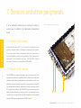
7. Sensors and other peripherals 26
7.1 Ambient light sensor 26
7.2 Digital motion sensor 27
7.3 IR receiver module 27
7.4 RGB LED 27
7.5 Temperature sensor 28
7.6 Real-time clock (RTC) 28
What’s next 30
Table of contents


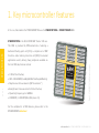
mikromedia 4 for STM32 CAPACITIVE is a compact
development board designed as a complete solution for
the rapid development of multimedia and GUI-centric
applications. By featuring a 4.3” capacitive touch screen
driven by the powerful graphics controller that can display
the 24-bit color palette (16.7 million colors), along with a
DSP-powered embedded sound CODEC IC, represents a
perfect solution for any type of multimedia application.
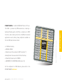
At its core, there is a powerful 32-bit STM32F407ZGT6 or
STM32F746ZGT6 microcontroller (referred to as “host MCU”
in the following text), produced by STMicroelectronics,
which provides sufficient processing power for the most
demanding tasks, ensuring fluid graphical performance and
glitch-free audio reproduction.
However, this development board is not limited to
multimedia-based applications only: mikromedia 4 for STM32
CAPACITIVE (“mikromedia 4” in the following text) features
USB, Ethernet, RF connectivity options, digital motion
sensor, piezo-buzzer, battery charging functionality, SD-
Card reader, RTC, and much more, expanding its use beyond
the multimedia. Two standardized 1x26 pin headers expose
the available MCU pins to the user, adding another layer of
expandability. By using mikromedia 4 shield, connectivity
can be further expanded with several mikroBUS
™
sockets,
additional connectors, peripherals, and so on.
The usability of mikromedia 4 does not end with its ability
to accelerate the prototyping and application development
stages: it is designed as the complete solution which can
be implemented directly into any project, with no additional
hardware modifications required. Four mounting holes
(3.2mm / 0.126”) at all four corners allow simple installation
with mounting screws. For most applications, a nice stylish
casing is all that is needed to turn the mikromedia 4
development board into a fully functional, high-performance,
feature-rich design.

P A G E 6
mikromedia 4 for STM32 CAPACITIVE U S E R M A N U A L
STM32F407ZGT6
1. Key microcontroller features
STM32F407ZGT6 is the 32-bit RISC ARM
®
Cortex
®
-M4 core.
This MCU is produced by STMicroelectronics, featuring a
dedicated floating-point unit (FPU), a complete set of DSP
functions, and a memory protection unit (MPU) for elevated
application security. Among many peripherals available on
the host MCU, key features include:
∫ 1 MB of Flash memory
∫ 192 + 4 KB of SRAM (including 64 KB of Core Coupled Memory)
∫ Adaptive real-time accelerator (ART Accelerator
™
)
allowing 0-wait state execution from Flash memory
∫ Operating frequency up to 168 MHz
∫ 210 DMIPS / 1.25 DMIPS/MHz (Dhrystone 2.1)
For the complete list of MCU features, please refer to the
STM32F407ZGT6 datasheet
At its core, mikromedia 4 for STM32 CAPACITIVE uses the STM32F407ZGT6 or STM32F746ZGT6 MCU.
APB2 84MHz
3 x ADC
temperature sensor
1 x SPI
2 x USART
3 x TIMER 16-bit
2 x TIM/PWM 16-bit
SDIO/MMC
2 x CAN
3 x I2C
2 x SPI
2 x UART
2 x USART
5 x TIMER 16-bit
2 x TIMER 32-bit
APB1 42MHz
2 x DAC
2 x TIMER 16-bit
WWDG
RTC
IWDG
SRAM 176 KB
FLASH 1MB
EXT. MEM. CONTR
DMA 2
ETH. MAC 10/100
JTAG & SW
USB OTG FS
CAM. INTERFACE
RNG
DMA 1
SRAM 16KB
USB OTG HS
POWER / RESET
AHB BUS - MATRIX
GPIO PORT
(A,B,C,D,E,F,G,H,I)
ARM
Cortex™-M4
STM32F407ZG
Figure 1: STM32F407ZGT6 MCU block schematic

P A G E 7
mikromedia 4 for STM32 CAPACITIVE U S E R M A N U A L
APB2 84MHz
3 x ADC
temperature sensor
4 x SPI
2 x USART
3 x TIMER 16-bit
2 x TIM/PWM 16-bit
SDIO/MMC
2 x CAN
4 x I2C
2 x SPI
4 x UART
2 x USART
5 x TIMER 16-bit
2 x TIMER 32-bit
APB1 42MHz
2 x DAC
3 x TIMER 16-bit
WWDG
RTC
IWDG
SRAM 240 KB
FLASH 1MB
EXT. MEM. CONTR
DMA 2
ETH. MAC 10/100
JTAG & SW
USB OTG FS
CAM. INTERFACE
RNG
DMA 1
SRAM 16KB
USB OTG HS
POWER / RESET
AHB BUS - MATRIX
GPIO PORT
(A,B,C,D,E,F,G,H,I)
ARM
Cortex™-M7
STM32F746ZGT6
MCUs FEATURES
STM32F746ZGT6 is the 32-bit RISC ARM
®
Cortex
®
-M7 core.
This MCU is produced by STMicroelectronics, featuring a
dedicated floating-point unit (FPU), a complete set of DSP
functions, and a memory protection unit (MPU) for elevated
application security. Among many peripherals available on
the host MCU, key features include:
∫ 1 MB Flash memory
∫ 320 KB of SRAM
∫ Adaptive real-time accelerator (ART Accelerator
™
)
allowing 0-wait state execution from Flash memory
∫ Operating frequency up to 216 MHz
∫ 462 DMIPS / 2.14 DMIPS/MHz (Dhrystone 2.1)
For the complete list of MCU features, please refer to the
STM32F746ZGT6 datasheet
Figure 2: STM32F746ZGT6 MCU block schematic

P A G E 8
mikromedia 4 for STM32 CAPACITIVE U S E R M A N U A L
MCUs FEATURES
1
4
3
2
5
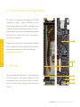
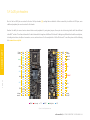
Figure 2: Front and back partial view
The host MCU can be programmed and debugged over the JTAG/SWD
compatible 2x5 pin header (2), labeled as PROG/DEBUG. This header
allows an external programmer (e.g. CODEGRIP or mikroProg) to be used.
To enable the JTAG interface, two SMD jumpers labeled as JP5 and JP6 (3)
must be populated. These jumpers are unpopulated by default, optimizing
the pin count so that more pins could be used for a large number of
onboard modules and peripherals.
Programming the microcontroller can also be done by using the bootloader
which is preprogrammed into the device by default. All the informations
about the bootloader software can be found on the following page:
www.mikroe.com/mikrobootloader
The board is equipped with the Reset button (4), which is located on the
front side of the board. It is used to generate a LOW logic level on the
microcontroller reset pin. The reset pin of the host MCU is also routed to
the pin 1 of the 1x26 pin header (5), allowing an external signal to reset
the device.
1.1 Microcontroller programming/debugging
1.2 MCU reset

P A G E 9
mikromedia 4 for STM32 CAPACITIVE U S E R M A N U A L
mikromedia 4
P A G E 9
P A G E 9
mikromedia 4
for STM32 CAPACITIVE
U S E R M A N U A L

P A G E 10
mikromedia 4 for STM32 CAPACITIVE U S E R M A N U A L
P A G E 10
mikromedia 4
for STM32 CAPACITIVE
U S E R M A N U A L
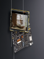
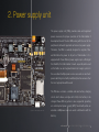
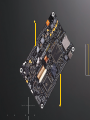
The power supply unit (PSU) provides clean and regulated
power, necessary for proper operation of the mikromedia 4
development board. The host MCU, along with the rest of the
peripherals, demands regulated and noise-free power supply.
Therefore, the PSU is carefully designed to regulate, filter,
and distribute the power to all parts of mikromedia 4. It is
equipped with three different power supply inputs, offering all
the flexibility that mikromedia 4 needs, especially when used
on the field or as an integrated element of a larger system. In
the case when multiple power sources are used, an automatic
power switching circuit with predefined priorities ensures that
the most appropriate will be used.
The PSU also contains a reliable and safe battery charging
circuit, which allows a single-cell Li-Po/Li-Ion battery to be
charged. Power OR-ing option is also supported, providing
an uninterrupted power supply (UPS) functionality when an
external or USB power source is used in combination with the
battery.
2. Power supply unit
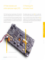
Figure 3: Power supply unit view
mikromedia 4 for STM32 CAPACITIVE U S E R M A N U A L

P A G E 11
mikromedia 4 for STM32 CAPACITIVE U S E R M A N U A L
2.1 Detailed description
POWER SUPPLY
The PSU has a very demanding task of providing power for the host MCU
and all the peripherals onboard, as well as for the externally connected
peripherals. One of the key requirements is to provide enough current,
avoiding the voltage drop at the output. Also, the PSU must be able to
support multiple power sources with different nominal voltages, allowing
switching between them by priority. The PSU design, based on a set of
high-performance power switching ICs produced by Microchip, ensures a
very good quality of the output voltage, high current rating, and reduced
electromagnetic radiation.
At the input stage of the PSU, the MIC2253, a high-efficiency boost regulator
IC with overvoltage protection ensures that the voltage input at the next
stage is well-regulated and stable. It is used to boost the voltage of low-
voltage power sources (a Li-Po/Li-Ion battery and USB), allowing the next
stage to deliver well-regulated 3.3V and 5V to the development board. A set
of discrete components are used to determine if the input power source
requires a voltage boost. When multiple power sources are connected
at once, this circuitry is also used to determine the input priority level:
externally connected 12V PSU, power over USB, and the Li-Po/Li-Ion battery.
The transition between available power sources is designed to provide
uninterrupted operation of the development board.
The next PSU stage uses two MCP16331, highly integrated, high-efficiency,
fixed frequency, step-down DC-DC converters, capable of providing up
to 1.2A. Each of the two buck regulators is used to supply power to the
corresponding power supply rail (3.3V and 5V), throughout the entire
development board and connected peripherals.
The MCP1501, a high-precision buffered voltage reference from Microchip
is used to provide a very precise voltage reference with no voltage drift. It
can be used for various purposes: the most common uses include voltage
references for A/D converters, D/A converters, and comparator peripherals
on the host MCU. The MCP1501 can provide up to 20mA, limiting its use
exclusively to voltage comparator applications with high input impedance.
Depending on the specific application, either 3.3V from the power rail,
or 2.048V from the MCP1501 can be selected. An onboard SMD jumper
labeled as REF SEL offers two voltage reference choices:
∫ REF: 2.048V from the high-precision voltage reference IC
∫ 3V3: 3.3V from the main power supply rail
2.2 Voltage reference

P A G E 12
mikromedia 4 for STM32 CAPACITIVE U S E R M A N U A L
2.3 PSU connectors
The USB-C connector (labeled as CN4) provides power from the USB host
(typically PC), USB power bank, or USB wall adapter. When powered over the
USB connector, the available power will depend on the source capabilities.
As explained, the advanced design of the PSU allows several types of power
sources to be used, offering unprecedented flexibility: when powered by
a Li-Po/Li-Ion battery, it offers an ultimate degree of autonomy. For
situations where the power is an issue, it can be powered by an external
12VDC power supply, connected over the 5.5mm barrel connector or over
the two-pole screw terminal. Power is not an issue even if it is powered
over the USB cable. It can be powered over the USB-C connector, using
power supply delivered by the USB HOST (i.e. personal computer), USB wall
adapter, or a battery power bank.
There are three power supply connectors available, each with its unique
purpose:
∫ CN4: USB-C connector (1)
∫ TB1: Screw terminal for an external 12VDC PSU (2)
∫ CN6: Standard 2.5mm pitch XH battery connector (3)
2.3.1 USB-C connector
1 32
Figure 4: Power supply connectors view

P A G E 13
mikromedia 4 for STM32 CAPACITIVE U S E R M A N U A L
POWER SUPPLY
An external 12V power supply can be connected over the 2-pole screw
terminal (labeled as TB1). When using an external power supply, it is
possible to obtain an optimal amount of power, since one external power
2.3.2 12VDC screw terminal
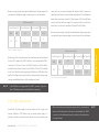
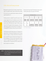
Figure 5: USB power supply table
Figure 6: External power supply table
USB power supply
Input Voltage [V] Output Voltage [V]
3.3
5
3.3 & 5
1.2
1.2
0.7 & 0.7
3.96
6
5.81
Max Current [A] Max Power [W]
MIN
4.4 5.5
MAX
External power supply
Input Voltage [V] Output Voltage [V]
3.3
5
3.3 & 5
1.2
1.2
1.2 & 1.2
3.96
6
9.96
Max Current [A] Max Power [W]
MIN
10.6 14
MAX
When using a PC as the power source, the maximum power can be obtained
if the host PC supports the USB 3.2 interface, and is equipped with USB-C
connectors. If the host PC uses the USB 2.0 interface, it will be able to
provide the least power, since only up to 500 mA (2.5W at 5V) is available
in that case. Note that when using longer USB cables or USB cables of low
quality, the voltage may drop outside the rated operating voltage range,
causing unpredictable behavior of the development board.
N O T E
N O T E
If the USB host is not equipped with the USB-C connector, a Type A to
Type C USB adapter may be used (included in the package).
When connecting an external power supply over the screw terminal,
make sure that the polarity of the wires is matched with the 12VDC
connector on the development board, according to the marked pins
of screw terminal.
Maximum power ratings, along with the allowed input voltage range in the
case when the USB power supply is used, are given in the table below:
supply unit can be easily exchanged with another, while its power and
operating characteristics can be decided per application. The development
board allows a maximum current of 1.2A per power rail (3.3V and 5V) when
using an external 12V power supply. The screw terminal is a good choice
when there is no connector installed at the end of the PSU cable.
Maximum power ratings, along with the allowed input voltage range in the
case when the external power supply is used, are given in the table below:

P A G E 14
mikromedia 4 for STM32 CAPACITIVE U S E R M A N U A L
P A G E 14
mikromedia 4
for STM32 CAPACITIVE
U S E R M A N U A L
When powered by a single-cell Li-Po/Li-Ion battery, mikromedia 4 offers an
option to be operated remotely. This allows complete autonomy, allowing
it to be used in some very specific situations: hazardous environments,
agricultural applications, etc.
The battery connector is a standard 2.5mm pitch XH connector. It allows
a range of single-cell Li-Po and Li-Ion batteries to be used. The PSU of
mikromedia 4 offers the battery charging functionality, from both the USB
connector and the 12VDC/external power supply. The battery charging
circuitry of the PSU manages the battery charging process, allowing the
optimal charging conditions and longer battery life. The charging process
is indicated by BATT LED indicator, located on the front of mikromedia 4.
The PSU module also includes the battery charger circuit. Depending on the
operational status of the mikromedia 4 development board, the charging
current can be either set to 100mA or 500mA. When the development
board is powered OFF, the charger IC will allocate all available power for the
battery charging purpose. This results in faster charging, with the charging
current set to approximately 500mA. While powered ON, the available
charging current will be set to approximately 100 mA, reducing the overall
power consumption to a reasonable level.
2.3.3 Li-Po/Li-Ion XH battery connector
Maximum power ratings along with the allowed input voltage range when
the battery power supply is used, are given in the table below:
Figure 7: Battery power supply table
Battery power supply
Input Voltage [V] Output Voltage [V]
3.3
5
3.3 & 5
1.2
1.1
0.6 & 0.6
3.96
5.5
4.98
Max Current [A] Max Power [W]
MIN
3.5 4.2
MAX
N O T E Using low-quality USB hubs, and too long or low-quality USB cables,
may cause a significant USB voltage drop, which can obstruct the
battery charging process.
P A G E 14
POWER SUPPLY

2.4 Power redundancy and
uninterrupted power supply (UPS)
2.5 Powering up the
mikromedia 4 board
The PSU module supports power supply redundancy: it will automatically
switch to the most appropriate power source if one of the power sources
fails or becomes disconnected. The power supply redundancy also allows
for an uninterrupted operation (i.e. UPS functionality, the battery will still
provide power if the USB cable is removed, without resetting mikromedia 4
during the transition period).
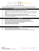
After a valid power supply source is connected (1) in our case with a single-
cell Li-Po/Li-Ion battery, mikromedia 4 can be powered ON. This can be
done by a small switch at the edge of the board, labeled as SW1 (2). By
switching it ON, the PSU module will be enabled, and the power will be
distributed throughout the board. A LED indicator labeled as PWR indicates
that the mikromedia 4 is powered ON.
POWER SUPPLY
P A G E 15
mikromedia 4 for STM32 CAPACITIVE U S E R M A N U A L
Figure 8: Battery power supply connection
2
1

P A G E 16
mikromedia 4 for STM32 CAPACITIVE U S E R M A N U A L
CAPACITIVE DISPLAY
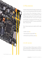
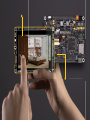
3. Capacitive display
A high-quality 4.3” TFT true-color display with a capacitive
touch panel is the most distinctive feature of the mikromedia 4.
The display has a resolution of 480 by 272 pixels, and it can
display up to 16.7M of colors (24-bit color depth). The display
of mikromedia 4 features a reasonably high contrast ratio
of 500:1, thanks to 10 high-brightness LEDs used for the
backlighting.
The display module is controlled by the SSD1963 (1)
graphics
driver IC from Solomon Systech. This is a powerful graphics
coprocessor, equipped with 1215KB of frame buffer memory.
It also includes some advanced features such as the hardware
accelerated display rotation, display mirroring, hardware
windowing, dynamic backlight control, programmable color
and brightness control, and more.
The capacitive multi-touch panel, based on the FT5216 CTP
controller, allows the development of interactive applications,
offering a touch-driven control interface. The touch panel
controller uses the I2C interface for the communication
with the host controller. This advanced multi-touch panel
controller supports gestures, including zoom and swipe in all
four directions.
Equipped with high-quality 4.3” display (2) and the multi-
touch controller that supports gestures, mikromedia 4
represents a very powerful hardware environment for
building various GUI-centric Human Machine Interface (HMI)
applications.

1
2
Figure 9: Display and SSD1963 view

P A G E 18
mikromedia 4 for STM32 CAPACITIVE U S E R M A N U A L
P A G E 18
mikromedia 4
for STM32 CAPACITIVE
U S E R M A N U A L
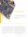
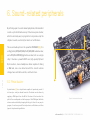
4. Data storage
The mikromedia 4 development board is equipped with two
types of storage memory: with a microSD card slot and a
Flash memory module.
4.1 microSD card slot 4.2 External flash storage
The microSD card slot (1) allows storing large amounts of data externally,
on a microSD memory card. It uses the Secure digital input/output
interface (SDIO) for communication with the MCU. The microSD card
detection circuit is also provided on the board. The microSD card is the
smallest SD Card version, measuring only 5 x 11 mm. Despite its small
size, it allows tremendous amounts of data to be stored on it. In order to
read and write to the SD Card, a proper software/firmware running on the
host MCU is required.
mikromedia 4 is equipped with the SST26VF064B Flash memory (2). The
Flash memory module has a density of 64 Mbits. Its storage cells are
arranged in 8-bit words, resulting in 8Mb of non-volatile memory in total,
available for various applications. The most distinctive features of the
SST26VF064B Flash module are its high speed, very high endurance, and
very good data retention period. It can withstand up to 100,000 cycles, and
it can preserve the stored information for more than 100 years. It also uses
the SPI interface for the communication with the MCU.
12
Figure 9: MicroSD card slot view
mikromedia 4 for STM32 CAPACITIVE U S E R M A N U A L
P A G E 18
DATA STORAGE

P A G E 19
mikromedia 4 for STM32 CAPACITIVE U S E R M A N U A L
P A G E 19
mikromedia 4
for STM32 CAPACITIVE
U S E R M A N U A L
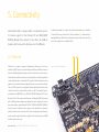
5. Connectivity
mikromedia 4 offers a huge number of connectivity options.
It includes support for the Ethernet, RF and USB (HOST/
DEVICE). Besides those options, it also offers two 1x26 pin
headers, which are used to directly access the MCU pins.
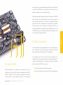
5.1 Ethernet
Ethernet is a popular computer networking technology for local area
networks (LAN). Systems communicating over Ethernet divide a stream of
data into individual packets, known as frames. Each frame contains source
and destination addresses and error-checking data so that damaged data
can be detected and re-transmitted. This makes the Ethernet protocol very
popular for communication over longer distances or in noisy environments.
The host MCU features an integrated Ethernet peripheral module, which
contains the entire communication stack on-chip. The physical layer is
provided by the LAN8720A (1), an RMII 10/100 Mbit Ethernet PHY IC from
Microchip. This IC has many useful features, including flexPWR
®
technology
with a flexible power management architecture and a support for various
low-power modes, compliance with ISO 802-3/IEEE and IEEE802.3/802.3u
frame formats, loopback modes support, auto-negotiation, automatic
polarity detection and correction, link status change wake-up detection,
vendor specific register functions, support for the reduced pin count RMII
interface, and much more.
It allows mikromedia 4 to connect to an Ethernet network over its shield as
TX and RX lines are routed to the 1x26 pin headers (2). mikromedia 4 is
equipped with two LED indicators, which are located on the front side. They
are used to signal status and data traffic.
Figure 10: 1x26 pins-header view
12
mikromedia 4 for STM32 CAPACITIVE U S E R M A N U A L

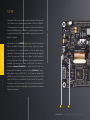
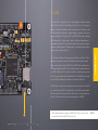
5.2 RF
mikromedia 4 offers communication over the world-wide ISM radio band.
The ISM band covers a frequency range between 2.4GHz and 2.4835GHz.
This frequency band is reserved for industrial, scientific, and medical use
(hence the ISM abbreviation). In addition, it is globally available, making it
a perfect alternative to WiFi, when the M2M communication over a short
distance is required.
mikromedia 4 uses the nRF24L01+ (1), a single-chip 2.4GHz transceiver
with an embedded baseband protocol engine, produced by Nordic
Semiconductors. It is a perfect solution for ultra-low power wireless
applications. This transceiver relies on the GFSK modulation, allowing data
rates in the range from 250 kbps, up to 2 Mbps. The GFSK modulation
is the most efficient RF signal modulation scheme, reducing the required
bandwidth, thus wasting less power. The nRF24L01+ also features a
proprietary Enhanced ShockBurst
™
, a packet-based data link layer.
Besides other functionalities, it offers a 6-channel MultiCeiver
™
feature,
which allows using the nRF24L01+ in a star network topology. The
nRF24L01+ uses the SPI interface to communicate with the host MCU.
Along the SPI lines, it uses additional GPIO pins for the SPI Chip Select,
Chip Enable, and for the interrupt. The RF section of the mikromedia 4
also features a small chip antenna (2), reducing the need for additional
hardware components.
12
P A G E 20
CONNECTIVITY
mikromedia 4 for STM32 CAPACITIVE U S E R M A N U A L
Page is loading ...
Page is loading ...
Page is loading ...
Page is loading ...
Page is loading ...
Page is loading ...
Page is loading ...
Page is loading ...
Page is loading ...
Page is loading ...
Page is loading ...
Page is loading ...
-
 1
1
-
 2
2
-
 3
3
-
 4
4
-
 5
5
-
 6
6
-
 7
7
-
 8
8
-
 9
9
-
 10
10
-
 11
11
-
 12
12
-
 13
13
-
 14
14
-
 15
15
-
 16
16
-
 17
17
-
 18
18
-
 19
19
-
 20
20
-
 21
21
-
 22
22
-
 23
23
-
 24
24
-
 25
25
-
 26
26
-
 27
27
-
 28
28
-
 29
29
-
 30
30
-
 31
31
-
 32
32


Mikroe mikromedia 5 User manual
- Type
- User manual
- This manual is also suitable for
Ask a question and I''ll find the answer in the document
Finding information in a document is now easier with AI
Related papers
-
Mikroe Air Quality Click User manual
-
-
Mikroe TMPM4K User manual
-
Mikroe MIKROE-5134 User manual
-
Mikroe 23LC1024 Operating instructions
-
Mikroe 8051-Ready User manual
-
-
Mikroe RS-485 User guide
-
Mikroe MMA8491Q User manual
-
Mikroe Port Expander User manual
Other documents
-
mikroElektronika MIKROE-3617 Operating instructions
-
-
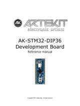 Artekit AK-STM32-DIP36 Reference guide
-
-
mikroElektronika MCP2551 User manual
-
mikroElektronika Click Booster Pack Operating instructions
-
Sunricher SR-SPI(RF/WiFi) User manual
-
 ABL electronic PIC18 User manual
-
 Sycamore SY8941 Owner's manual
-


