Page is loading ...

USER'S GUIDE
LEN.MAN.UPS.146 Rev.2.00/2009

CONTENTS
1. SAFETY INSTRUCTIONS 1
2. INTRODUCTION 2
3. DISPLAY PANEL AND COMPONENTS 5
3.1 Display panel 5
3.2 Components 7
4. INSTALLATION 12
5. OPERATION 17
5.1 Start-up the UPS 17
5.2 Turning on and turning off the UPS for the next time 17
5.3 When blackout or power fails 17
5.4 When UPS is overloaded 18
5.5 No load shutdown mode 18
5.6 Economy mode 18
5.7 Sleep mode 18
5.8 UPS self-test 18
5.9 Self-test cancellation 18
5.10 Mute alarm sound 19
5.11 Force bypass 19
5.12 Maunal maintenance bypass 19
5.13 Emergency Power Off (EPO) 19
6. LCD DISPLAY DESCRIPTION 20
7. SETTING 23
7.1 Enter password 23
7.2 System control setting 24
7.3 Time and date setting 24
7.4 Parameter setting 26
8. MAINTENANCE 27
9. TROUBLESHOOTING 28
10. SOFTWARE INSTALLATION 30

SAFETY INSTRUCTIONS
Please read carefully and follow this LEONICS NB S-series/NBP S-series UPS guide.
Important : Please keep this manual for reference in order to use the LEONICS UPS properly and safely. This
user's guide contains instructions for installation, maintenance, operation and unit etc.
For product safety, please check this product annually by our service qualified personnel or if there are any
symptoms of problems which are not mentioned in this guide or any queries, please contact your LEONICS local
distributors, LEONICS Service Center, send e-mail to [email protected] or visit www.leonics.com.
For your convenience and quick reference for LEONICS UPS service, please fill
the requested information in the blanks below.
LEONICS UPS model: ___________________________________________
Serial number: ________________________________________________
Purchased date: ________________________________________________
Purchased from: ________________________________________________
CAUTION
Risk of electric shock, DO NOT remove cover. No user serviceable part inside,
please refer servicing to qualified service personnel.
1.1 Electrical Safety
1.1.1 Do not work alone where there is danger of shock.
1.1.2 Contact with live conductors will cause burns and dangerous electric shock.
1.1.3 Please allow ONLY a certified electrician to wire your system permanently.
1.1.4 Periodically check your cable, outlets and power source to make sure that they are in good condition.
1.1.5 To reduce risk from electric shock if you can not find the electrical ground (
)of the building, unplug
the UPS from the AC source before plug in your load at the rear side of the UPS. Then, plug in the UPS to
AC source.
1.1.6 Do not touch any metal parts or any electrical connection when UPS is operating.
1.1.7 It is recommended to connect the UPS to a three wire AC source (two live wires and ground) which
connects to a protected circuit such as employs a fuse or circuit breaker.
1.2 CAUTION ! Safety guide for installation and operation
1.2.1 Before installation or using this unit, read all instructions, caution markings on the UPS and all
connected load, and all sections of this user guide.
1.2.2 Install this unit in a temperature and humidity controlled indoor area with adequate air flow and away
from chemical particles or flammable substances. Avoid installing the unit near radio transmission
station, heat dissipation equipment and direct sunlight.
1.2.3 This unit has ventilation grills. Ensure that sufficient ventilation is provided. DO NOT block the
ventilation grills.
1.2.4 Use insulated tools to reduce your risk of electric shock.
1.2.5 Remove all jewelry or other metal objects such as rings, necklace, bracelets and watches when installing
this product.
1.2.6 Properly wiring the cables as shown in the wiring diagram.
- 1 -

- 2 -
1.2.7 Before connecting the communication interface signal cable to computer, turn off the UPS and
disconnect it from the utility line.
1.2.8 Turn on the UPS before turn on the load to prevent surge from the loads.
1.2.9 DO NOT connect utility power to the UPS OUTPUT. This may cause the UPS damaged.
1.2.10When heavy rain, avoid using electronic instruments including
UPS to pre
vent it from lightning.
1.2.11Use soft cloth to clean the UPS when it is OFF. DO NOT clean it with solvent.
1.2.12DO NOT use the UPS with life recovery instruments. The failure of UPS may cause life recovery
instruments failure or effect to their performance or
effect
to the safety system of those instruments.
1.3 Warning ! Battery Safety
1.3.1 The UPS has hazardous voltages inside, do not disassemble any parts of UPS except for the battery.
1.3.2 Users are not allowed to repair, recondition or disassemble the UPS. This must be done by LEONICS
qualified technicians only.The battery that is inside your UPS can be recycled. It contains LEAD, which is
harmful to health and the environment. If It can not be disposed of properly.
1.3.3 Do not dispose of batteries in a fire. They may be exploded.
1.3.4 Do not disassemble batteries. They contains poisonous electrolyte which is harmful to your skin and
eyes.
1.3.5 Replace batteries with the same type and rating and follow the proper battery replacement procedure.
1.3.6 When replacing a battery, use tools with insulated handles and remove any watch, rings or other metal
objects that you wear in order to avoid electric shock.
1.3.7 If user has to keep the UPS or does not use if for long time, recharge the battery every 3 months in order
to preserve the battery. To recharge the battery, connect it to the AC utility and turn on the UPS for 8
hours.
INTRODUCTION
2.1 General
LEONICS NB S-series/NPB S-series UPS is a True On-line Double conversion uninterruptible power supply which
is the highest quality power protection system to protect against all utility power problems. With LED and LCD
displays, user can view the UPS operating status anytime.
True On-Line Double conversion system has two operation steps. First, it convert alternative current (AC) to
direct current (DC) Some of the direct current will flow to charge the battery to be backup power and the rest will
invert to alternative current and then supply to load. If the AC input is disconnected, the UPS will invert the direct
current from battery to alternative current and supply to load. UPS will supply AC power to load continuously.
Vocabulary
Load: Any equipment which is plugged into the UPS and gets power from the UPS such
as a computer, printer, fax machine or modem.
UPS : NB S-Series / NBP S-series UPS
VA : The unit of UPS power rating showing its capacity.

- 3 -
2.2 Features
-True On-line pure sine wave
-Microprocessor controller
-Stable output frequency (Crystal control)
-Over current and short circuit protection
-Built-in output isolation transformer
-Load safe battery test (available in NBP S-series only)
- EMI/RFI and power line noise protection
-Automatic bypass overload protection
-Automatic bypass transfer switch (zero transfer time)
- DC start (AC start without battery (option))
-Manual self-test
- RS-232 communication port
-Sealed lead acid maintenance free battery
- LED indicator and LCD display
2.3 UPS Operation
2.3.1
When utility power and loads are normal
Above diagram shows how UPS works when utility power (AC line) is normal and UPS has less
than100% load. UPS converts utility power from alternative current (AC) to direct current (DC) at
RECTIFIER. Some of the DC power flow to charge battery to be backup power and the rest flow
directly to INVERTER to invert power to high quality and stable AC power. Then, supply to load.
2.3.2
When utility power is normal but overload.

- 4 -
Above diagram shows how UPS works when utility power is normal and UPS has more than 100%
load. UPS converts utility power at RECTIFIER / CHARGER section to charge battery only. The power
supplied to load directly is from utility line.
2.3.3
When utility power fail but loads are normal
Above diagram shows how UPS works when utility power fails such as blackout, brownout, under
voltage, over voltage or frequency fault and UPS has less than 100% load. UPS draws backup power
from battery to invert to AC power and continuously supplies to load.
2.3.4
Use maintenance bypass switch when UPS is malfunction (option)
Above diagram shows how system works when UPS is malfunction. User is allow to temporary run
the system by turning the manual bypass switch from position A to B or at BYPASS position. All loads will
get power supplied directly from utility line. Then, contact us or our nearest service center.

- 5 -
DISPLAY PANEL AND COMPONENTS
3.1 Display panel
3.1.12
3.1.14
3.1.15
3.1.16
3.1.17
3.1.1
3.1.2
3.1.3
3.1.4
3.1.13
3.1.5
3.1.6
3.1.7
3.1.8
3.1.9
3.1.10
3.1.11
3.1.1 ON button: The button to turn on the UPS, test the operation and mute alarm sound.
3.1.2
OFF button: The button to turn off the UPS and force the UPS to bypass the power source.
3.1.3
, , and buttons: The buttons to show the UPS parameters on LCD display.
3.1.4
LCD display: The screen to display parameter values.
3.1.5
LINE indicator: Indicate status of main power source.
Lit means the input voltage is normal.
Off means the input voltage of the main power source is out of range.
3.1.6
BYPASS indicator: Indicates status of bypass power source.
Lit means the voltage and frequency of the bypass power source is in the range.
Off means the voltage of the bypass power source is out of range or the frequency is out of
synchronized range.
3.1.7
RECTIFIER/CHARGER indicator: Indicates status of RECTIFIER and CHARGER section.
Lit means RECTIFIER and CHARGER operate normally.
Blink means RECTIFIER and CHARGER are just starting the operation.
Off means RECTIFIER and CHARGER stop operating.
3.1.8
INVERTER indicator: Indicates status of INVERTER section.
Lit means INVERTER section is operating and synchronizing frequency with the bypass power
source.
Blink means INVERTER section is operating but does not synchronize frequency with the bypass
power source.
Off means INVERTER section stop operating.

- 6 -
3.1.9 INV. SUPPLY indicator: Indicates status of power from INVERTER section which supplies to loads.
Lit means loads consume protected power from the UPS.
Off means the protected power from the UPS does not supply to loads.
3.1.10
AUTO BYPASS indicator: Indicates status of BYPASS power source which is supplying to loads
directly when overload, inverter fault or force bypass condition.
Lit means loads consume power from BYPASS power source directly by press and hold
OFF button to force bypass condition.
Slow blink means loads consume power from BYPASS power source directly automatically.
Off means there is no power from BYPASS power source supplying to load.
3.1.11
MAINTENANCE BYPASS indicator: Indicates status of BYPASS power source which is supplying to loads
directly when MAINTENANCE BYPASS SWITCH is set at position BYPASS (B)
Lit means loads consume power through MAINTENANCE BYPASS SWITCH.
Blink means MAINTENANCE BYPASS SWITCH is set at position AUTO (A) .
3.1.12
LOAD LEVEL indicator: Indicates the load quantity comparing to full capacity of the UPS. The indicator
shows from 25% (bottom LED) to OVERLOAD (top LED).
1
st
(bottom) lamp is lit means total load quantity is higher than no load condition level.
2 lamps are lit means total load quantity is between 26-49%.
3 lamps are lit means total load quantity is between 50-74%.
4 lamps are lit means total load quantity is between 75-99%.
5 lamps are lit means total load quantity is over 100%. The UPS is overloaded.
Recommend to reduce some loads.
3.1.13
BATTEY LEVEL indicator: Indicates the level of battery power comparing to the full level. The indicator
shows from replace battery (bar left LED) to full battery (bar right LED).
1
st
(left) lamp is lit means the battery power is very low and blinks when the battery should be
replaced.
2 lamps are lit means the battery power is low and blinks to alarm.
3 lamps are lit means the battery power is moderate.
4 lamps are lit means the battery power is full.
3.1.14
ON indicator: Indicates the UPS operation normally.
Lit means the UPS is operating normally.
Very slow blink means loads consume power from BYPASS power source directly by press and
hold OFF button to force bypass condition.
Slow blink means the UPS stop operating and waits to restart by startup schedule.
Fast blink means the UPS is testing the operation.
Off means the UPS stop operating.
3.1.15
SHUTDOWN indicator: Indicates the UPS stop operation or standby operation.
Lit means the UPS stop operating or UPS is in standby mode.
Slow blink means the UPS is going to shutdown due to a command from the computer.
Fast blink means the UPS is going to shutdown due to low battery or overload.
Off means the UPS does not standby or is not going to shutdown.
3.1.16
OVER TEMP./FAULT indicator: Indicates the UPS is over temperature or UPS is malfunction.
Lit means the UPS operates abnormally.
Fast blink means the UPS is over temperature.
Off means the UPS operates normally or is normal temperature.
3.1.17
ALARM indicator: Indicates the UPS has fault.
Blink means the UPS alarms fault.
Off means the UPS operates normally.

- 7 -
3.2 Components
AB
3.2.9
3.2.18
3.2.1
3.2.10
3.2.5
3.2.6
3.2.2
3.2.3
3.2.4
3.2.15
3.2.11
3.2.19
3.2.14
SNMP AGENT
NORMAL
PRECHARGE
MANUAL BYPASS
INPUT
220 VAC
1Ø 50Hz
OUTPUT
220 VAC
1Ø 50Hz
INPUT
CIRCUIT BREAKER
BATTERY
CIRCUIT BREAKER
BYPASS
RS-232
REMOTE TERMINAL
REMOTE STATUS INTERFACE
DI 2DI 1
GROUND
213456
7
891011 12 13 14
K1 K2 K4K3 K5 K6
NO NC
COMMON
NO NC NO NO NO NO
IT'S IMPORTANT TO OBSERVE THE CORRECT POLARITY WHEN
MAKING CONNECTION. REVERSE POLARITY CONNECTIONS
WILL DAMAGE THIS PRODUCT.
DO NOT
TURN THE BATTERY CIRCUIT BREAKER ON BEFORE
PRE-CHARGE UPS, AS IT MAY CAUSE DAMAGE TO THE UPS.
PRESS AND HOLD "PRECHARGE" BUTTON FOR 15 SECONDS AND
THEN TURN ON THE BATTERY CIRCUIT BREAKER.
DO NOT
CONNECT OR DISCONNECT THE CABLE TO THE BATTERY
EXTENSION MODULE BEFORE YOU HAVE TURNED THE BATTERY
CIRCUIT BREAKER OFF.
DO NOT
TURN THE BATTERY BREAKER ON WHEN THE BATTERY
EXTENSION MODULE IS DISCONNECTED FROM THE UPS.
LN LN
15 16
K7
NO NC
CAUTION
CAUTION FOR BATTERY EXTENSION
RISK OF ELECTRIC SHOCK, DO NOT REMOVE COVER.
NO USER SERVICEABLE PARTS INSIDE, REFER SERVICING TO
QUALIFIED SERVICE PERSONNEL.
WARNING
OUTPUT FUSE
15A 250VAC
OUTPUT
220 VAC 1Ø 50Hz
BATTERY EXTENSION
OFFOFF OFFOFF
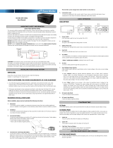
Rear panel of NB-2KS UPS

- 8 -
Rear panel of NBP-3KS, NBP-5KS and NBP-6KS UPS

Front panel of NBP-8KS and NBP-10KS UPS
- 9 -

Rear panel of NBP-8KS and NBP-10KS UPS
- 10 -

- 11 -
3.2.1 PRECHARGE: A button to press and hold for 5 seconds before turn on BATTERY circuit breaker
every time for safety. The capacitor will first charge in order to protect surge or spark when urn on
BATTERY circuit breaker.
3.2.2
MAINTENANCE MANUAL BYPASS SWITCH (option) : The switch to switch power source from AC utility
power to BYPASS power source for maintenance.
- NORMAL/AUTO: Select this position to tranfer loads to consume the protected power from UPS.
- BYPASS: Select this position to transfer loads to consume power from bypass power source when
the UPS need to maintenance.
3.2.3
RS232-PC: The port for connecting RS-232 cable from UPS to computer to send and receive electricity
data with Easy-Mon X (download Easy-Mon X at www.leonics.com).
3.2.4
REMOTE TERMINAL (option): The port to send and receive remote signal to display the operation of
the UPS via remote display or website.
3.2.5
REMOTE STATUS INTERFACE (option) : The terminal for sending remote contact signal; normally open
(NO), normally close (NC) and common (COM) to display the operating status of the UPS. The
descriptions of each signal pin are as follow.
3.2.5.1 DI1: Reserved.
3.2.5.2 DI1: Reserved.
3.2.5.3 GROUND: ground of digital input signal.
3.2.5.4 COMMON: COMMON pin of the contact signal.
3.2.5.5 K1 (NO, NC): UPS Normal / Fault (NO and NC contacts of K1 relay).
3.2.5.6 K2 (NO, NC): Loads are protected. (NO and NC contacts of K2 relay).
3.2.5.7 K3 (NO): Run on battery signal (NO contact of K3 relay).
3.2.5.8 K4 (NO): Bypass signal (NO contact of K4 relay).
3.2.5.9 K5 (NO): Low battery signal (NO contact of K5 relay).
3.2.5.10 K6 (NO): Overload signal (NO contact of K6 relay).
3.2.5.11 K7 (NO, NC): Alarm signal (NO and NC contacts of K7 relay).
3.2.6
SNMP AGENT (option): The socket for connecting computer network LAN cable to view electricity
data and UPS status via SNMP/HTTP (Read more details in Net Agent manual).
3.2.7
AC INPUT: The cable for connecting to AC outlet or AC power source (specific models only).
3.2.8
INPUT FUSE: The component for protecting from overload or short circuit current at the UPS input.
3.2.9
OUTPUT FUSE: The component for protecting loads from overload or short circuit current at the UPS
output (specific models only).
3.2.10
UPS OUTPUT: The socket to supply protect backup power to loads (specific models only).
3.2.11
INPUT circuit breaker: The circuit breaker for protecting from overload or short circuit current at the
main AC power source.
3.2.12
BYPASS INPUT circuit breaker (option): The circuit breaker for protecting from overload or short circuit
current at bypass power source.
3.2.13
OUTPUT circuit breaker (option): The circuit breaker for protecting loads from overload or short circuit
current at the UPS output.
3.2.14
BATTERY circuit breaker: The circuit breaker for protecting from overload or short circuit current at the
battery system.
3.2.15
INPUT terminal: The terminal for connecting input power from main AC power source to the UPS.
3.2.16
BYPASS INPUT terminal: The terminal for connecting input power from bypass power source to the
UPS.
3.2.17
PE/EARTH terminal ( ) : The terminal for connecting to ground system.
3.2.18
OUTPUT terminal: The terminal for connecting to loads.
3.2.19
BATTERY EXTENSION terminal(option): The terminal for connecting to external battery bank to
extend backup time.

- 12 -
INSTALLATION
4.1 Preparation
4.1.1 Before you install the UPS, give it a through visual examination to ensure it has not been subjected to
shipping damage. If it is not in perfect condition, please contact your local distributor or service center
or e-mail to [email protected].
4.1.2 Installation of the UPS must be done by professional technicians only. Before installing or using this
unit, read all instructions, caution markings on the UPS and all connected load, and all sections of this
user guide.
4.1.3 Check the mains input voltage and alll connected load power rating to suit for UPS power rating.
4.1.4
Transportation
4.1.4.1 UPS has been fitted with casters to allow ease of transportation. UPS must be moved vertically.
4.1.4.2 Transport the UPS with its packaging until it arrive the installation location to avoid shipping
damages.
4.1.4
Location
4.1.5.1 For 2000 VA model or lower: Install the UPS at least 20 cm at the side and back to enable easy
access for installation, operation and maintenance.
4.1.5.2 For 3000 VA model or higher: Install the UPS at least 80 cm free space around the UPS to enable
easy access for installation, operation and maintenance.
4.1.5.3 Install at the floor that is capable of supporting the weight of the UPS.
4.1.5.4 Battery Extension Modules must be installed near by the UPS.
4.1.6
Working with Battery Extension Modules
Batteries are connected in series which have hazardous voltage upto 306-400 Vdc. Any battery
connection must be done by qualified technician only.
Warning: DO NOT work with batteries when UPS is operating.
4.1.7
Cable size
The cable sizes in the following table are calculated based on TIS. 11-2531 PVC insulated copper wire,
70 degree Celsius conductor temperature, 750 Volt 40 degree Celsius ambient temperature and
maximum 3 wires per conduit.
Note: -Maximum cable length must not exceed 10 metres. If in need of cable longer than 10 metres,
properly increase cable size to accommodate excessive length.
-For your safety, all cables should be wire in the suitable size conduits.
-The above data is for standard product only.
-For the battery extension module installation, please contact us.
Power rating
Main input cable (sq.mm.)
Bypass input cable
(sq.mm.)
Output cable (sq.mm.)
PE/Earth cable (
)
(sq.mm.)
1000 VA or lower
Power cord
-
-
-
2000 VA
2.5
2.5
1.5
1.5
3000 VA
2.5
2.5
2.5
2.5
5000 VA
6
6
4
4
6000 VA
6
6
6
4
8000 VA
10
10
6-10
4
10000 VA
16
16
16
6

AB
SNMP AGENT
NORMAL
PRECHARGE
MANUAL BYPASS
INPUT
220 VAC
1Ø 50Hz
OUTPUT
220 VAC
1Ø 50Hz
INPUT
CIRCUIT BREAKER
BATTERY
CIRCUIT BREAKER
BYPASS
RS-232
REMOTE TERMINAL
REMOTE STATUS INTERFACE
DI 2DI 1
GROUND
213456
7
89101112 13 14
K1 K2 K4K3 K5 K6
NO NC
COMMON
NO NC NO NO NO NO
IT'S IMPORTANT TO OBSERVE THE CORRECT POLARITY WHEN
MAKING CONNECTION. REVERSE POLARITY CONNECTIONS
WILL DAMAGE THIS PRODUCT.
DO NOT
TURN THE BATTERY CIRCUIT BREAKER ON BEFORE
PRE-CHARGE UPS, AS IT MAY CAUSE DAMAGE TO THE UPS.
PRESS AND HOLD "PRECHARGE" BUTTON FOR 15 SECONDS AND
THEN TURN ON THE BATTERY CIRCUIT BREAKER.
DO NOT
CONNECT OR DISCONNECT THE CABLE TO THE BATTERY
EXTENSION MODULE BEFORE YOU HAVE TURNED THE BATTERY
CIRCUIT BREAKER OFF.
DO NOT
TURN THE BATTERY BREAKER ON WHEN THE BATTERY
EXTENSION MODULE IS DISCONNECTED FROM THE UPS.
LN LN
15 16
K7
NO NC
CAUTION
CAUTION FOR BATTERY EXTENSION
RISK OF ELECTRIC SHOCK, DO NOT REMOVE COVER.
NO USER SERVICEABLE PARTS INSIDE, REFER SERVICING TO
QUALIFIED SERVICE PERSONNEL.
WARNING
OUTPUT FUSE
15A 250VAC
OUTPUT
220 VAC 1Ø 50Hz
BATTERY EXTENSION
OFFOFF OFFOFF
Main
Power Supply
Computer
Battery
Extension
Modules
(option)
Load Panel
AC Loads
L
N
PE
L
N
PE
Remote Panel
or Monitoring
SNMP/HTTP
Network
Installation diagram of NB-2KS UPS
4.2 Installation
- 13 -

- 14-
OFF
OFF OFF
OFF
AB
OFF
OUTPUT
CIRCUIT BREAKER
BYPASS INPUT
CIRCUIT BREAKER
Computer
SNMP/HTTP
Network
Remote Panel
or Monitoring
Main
Power Supply
L
N
Bypass
Power Supply
(option)
L
N
AC Loads
Battery
Extension
Modules
(option)
Installation diagram of NBP- 3KS, NBP -5KS and NBP-6KS UPS

- 15-
SNMP/HTTP
Network
Computer
Remote Panel
or Monitoring
Main
Power Supply
L
N
Bypass
Power Supply
(option)
L
N
AC Loads
Battery
Extension
Modules
(option)
Note: -For the single power source, it has to jump the cables between BYPASS INPUT terminal and
MAIN INPUT terminal of the UPS as shown in the installation diagram figures.
-If there are two power sources, it has to disconnect the jumping cables between BYPASS INPUT
terminal and MAININPUT terminal.
Installation diagram of NBP- 8KS and NBP-10KS UPS

- 16 -
4.2.1 Turn off all loads.
4.2.2 For 2000VA model or higher, Turn off all AC power source which supplies power to the UPS .
4.2.3 Turn off INPUT, BYPASS INPUT (if available), OUTPUT (if available) and BATTERY circuit breakers.
4.2.4 Connect RS-232 signal cable (if available) from the computer serial port to RS-232-PC port of the UPS.
4.2.5 Connect Remote terminal signal cable (if available) from remote panel or modem to REMOTE TERMINAL
port of the UPS.
4.2.6 Connect interface signal cables (if available) at REMOTE STATUS INTERFACE terminal to send and receive
remote contact signal (NO, NC, COM) for control or alarm such as PLC or buzzer.
Sample
Note: Contact rating 5A 250Vac / 5A 30Vdc
4.2.7 Connect earth cable at PE / EARTH (
) terminal.
4.2.8 Connect input cable from AC power source to the UPS.
For 1500 VA model or higher, connect the cable from AC power source at INPUT terminal of the UPS.
Connect NEUTRAL at N terminal of the UPS and connect LINE at L terminal of the UPS.
If there is single power source, jump BYPASS input terminal to INPUT terminal. If there is other power
source which is not primary power source, connect to BYPASS input terminal.
4.2.9 Connect loads to UPS.
4.2.9.1 For 1000 VA model or lower, connect loads to UPS OUTPUT outlets at the rear side of the
UPS.
4.2.9.2 For 1500 VA model or higher, connect the cable from OUTPUT terminal of the UPS to loads.
Connect NEUTRAL at N terminal of the UPS and connect LINE at L terminal of the UPS.
4.2.10In case of battery extension, remove fuse from the fuse holder or turn off circuit breaker at the battery
extension unit before connecting to the UPS. Then connect the positive (+) of the battery extension
unit to the positive (+) terminal of the UPS. And connect the negative (-) of the battery extension unit to
the negative (-) terminal of the UPS.
4.2.11 Verify all connections.
+ 12 Vdc
GND
COM
Test Sw.
Mute Sw.
12V Bazzer
12V indicator
NO
UPS contact signal

- 17 -
OPERATION
5.1 Start-up the UPS
5.1.1
For 1000 VA model or lower
5.1.1.1 Turn off all loads.
5.1.1.2 Press and hold PRECHARGE button for 5 seconds or until the LCD lit, then release. Turn on
BATTERY circuit breaker. BATTERY LEVEL indicator shows battery level.
Caution: DO NOT turn on BATTERY circuit breaker before precharge the UPS because the
UPS may be damaged.
Note: In case of battery extension, turn on BATTERY circuit breaker or FUSE circuit breaker
(if available) of the battery extension unit before pressing PRECHARGE button and turning on
BATTERY circuit breaker at the UPS.
5.1.1.3 Plug input cable or input power cord to AC receptacle. INPUT, BYPASS and RECTIFIER/CHARGER
indicators are lit.
5.1.1.4 Press and hold ON button for 2 seconds or until alarm beep sound to turn on the UPS.
The ON indicator blinks and UPS start up self-test automatically. After self test, if the UPS
operates normally, the display will show the operating status
5.1.1.5 Turn on connected loads.
5.1.2
For 1500 VA model or higher
5.1.2.1 Turn off all loads.
5.1.2.2 Press and hold PRECHARGE button for 5 seconds or until the LCD lit, then release. Turn on
BATTERY circuit breaker. BATTERY LEVEL indicator shows battery level.
Caution: DO NOT turn on BATTERY circuit breaker before precharge the UPS because the
UPS may be damaged.
Note: In case of battery extension, turn on BATTERY circuit breaker or FUSE circuit breaker
(if available) of the battery extension unit before pressing PRECHARGE button and turning on
BATTERY circuit breaker at the UPS.
5.1.2.3 Turn on INPUT circuit breaker and BYPASS circuit breaker (if available). INPUT, BYPASS and
RECTIFIER/CHARGER indicators are lit.
5.1.2.4 Press and hold ON button for 2 seconds or until alarm beep sound to turn on the UPS.
The ON indicator blinks and UPS start up self-test automatically. After self test, if the UPS
operates normally, the display will show the operating status
5.1.2.5 Turn on OUTPUT circuit breaker (if available).
5.1.2.6 Turn on connected loads.
5.2 Turning on and off the UPS for the next time
After finished the start-up procedure, press and hold OFF button until alarm beep sound once then
release to turn off the UPS. To turn on the UPS at the next time, Only press and hold ON button untilalarm
beep sound once then release.
5.3 When blackout or power fails
When blackout or power fails, the UPS continuously supplies power to loads for 15-90 minutes
(depending on load quantity and UPS power rating). UPS draw backup power from battery (INV. SUPPLY and
ALARM indicators blink and alarm sound). When the backup power in the battery is low, LOW BATT. indicator
(the 2
nd
from left) will blink and alarm sound rapidly to warn that the UPS will shutdown in a few minutes (Low

- 18 -
Battery Shutdown status). If the power returns to normal before the UPS goes to Low Battery Shutdown mode,
UPS will switch back to consume power from AC utility power and charge battery automatically.
5.4 When UPS is overloaded
When UPS is overloaded (OVERLOAD indicator lit, ALARM indicator blinks and alarm sound), the AUTO-
MATIC TRANSFER SWITCH will transfer load to consume power from bypass power source direclty (AUTO
BYPASS indicator blinks and alarm sound) for preventing the UPS damage. User should reduce some loads
until load quantity is about 75% and control the quantity not exceed 100% in order to make the loads
consume power from the UPS all the time.
5.5 No load shutdown mode
When the UPS is supplying backup power and there is no connected loads, UPS will shutdown auto-
matically after supplies backup power for 10 minutes in order to reserve the battery power. This feature is set
disabled in the standard product. (This feature is available in the UPS with Battery save / No Load Shutdown
mode)
5.6 Economy mode
Economy mode is an energy saving mode. In this operating mode, UPS transfer loads to consume
power from bypass power source when the bypass power source is normal and run the INVERTER operation to
be the backup source when the bypass power source fails.
5.7 Sleep mode
Sleep mode is an energy saving mode. In this operating mode, UPS transfer loads to consume power
from bypass power source and stop the INVERTER operation when UPS found no connected load or load
consume power from the UPS is lower than no load condtion setting. During Sleep mode, If there are loads
greater than set value, the INVERTER section will restart automatically and exit from sleep mode.
When UPS found no load and bypass power source fails, UPS will start INVERTER section and stand by
to be the backup power source when there is load.
5.8 UPS self-test
UPS tests the operation of RECTIFIER, CHARGER and INVERTER section. There are 4 types of self-test.
5.8.1
Start-up self-test
When press ON button to start-up the UPS, it tests the operation automatically.
5.8.2
Manual self-test
When the UPS is operating, double click the ON button to start manual self-test.
5.8.3
Schedule self-test (option)
User can set UPS self-test schedule via Easy-Mon X (Read more details in Easy-Mon X user’s guide in
the CD-ROM or at www.leonics.com).
5.8.4
Auto self-test (option)
User can set UPS self-test automatically every 2 weeks or every day. This feature is disabled in the
standard product.
Every test, if the battery is fully charged, the UPS will also check if the battery is still in good condition
or need to be replaced.
5.9 Self-test cancellation
Before the UPS starts INVERTER section test, user can double click the ON button to cancel the self-test.
/