Page is loading ...

22022613 Rev A
Installation and Owner’s Manual
U.S. and Canada call toll-free:
1-877-ROC-N-ROL
(1-877-762-6765)
Outside the U.S. and Canada, call:
(616) 243-3633
E-mail: support@amientertainment.net
www.amientertainment.net


AMI extends the original operator of this equipment the following warranty:
All parts are guaranteed to be free of defects in material and workmanship for the specific periods listed. AMI agrees to repair or replace
without charge during such period any part which proves defective upon examination by AMI. All costs of shipping a defective part to
AMI’s offices shall be borne by the original operator. AMI shall bear the shipping costs for the replacement of defective parts.
Component Warranty Period Conditions
(from date of shipment)
Electronic Circuit Boards 2 Years Parts
Core Computer Motherboard 1 Year Parts
Electrical & Mechanical Parts 2 Years Parts
LCD Display 1 Year Parts
Touchscreen Sensor 5 Years Parts
Touchscreen Controller 10 Years Parts
Hard Drive Life* *Full Replacement by AMI, at no charge, for the life
of the AMI Entertainment® contract.
In the case of parts supplied to AMI as components, AMI extends the same warranty period as extended by the original manufacturer.
The above warranty applies provided that all parts of the product have been serviced properly as directed in the service manual, and
provided the alleged defective part, upon examination by AMI, shall prove to be thus defective. Under no circumstances shall AMI be liable
for any incidental, consequential or special damages, losses or expenses arising from or in connection with the use of, or the inability to
use, the product for any purpose. AMI reserves the right to make any changes or improvements in its products without notice and
obligation, and without being required to make corresponding changes or improvements in products theretofore manufactured or sold.
This warranty will not apply to any product or any part which has been subjected to any accident, abuse, or misuse.
AMI ENTERTAINMENT NETWORK, INC. EXTENDS NO WARRANTY, EXPRESSED OR IMPLIED, TO PURCHASERS OR USERS OF ITS
PRODUCTS EXCEPT AS HEREIN SET FORTH, WHETHER BY OPERATION OF LAW OR OTHERWISE.
NiteHAWK JUKEBOX WARRANTY

NITESTAR DUET WALL
WARRANTY
This card completed by: Date_________________
Name____________________________ Company_______________________________
Street Address____________________________________________________________
City____________________________________ State_________ Zip________________
Telephone: Area Code____________ Number___________________________________
Model No._____________________ Serial No.__________________________________
Product Purchased From____________________________________________________
Please complete the following:
This product’s performance when first powered up was:
The overall quality of this product was:
The distributor support for this product was:
The operation manual and instructions are:
If there are any suggested product improvements or if problems are encountered during installation
and/or setup, please advise in the space provided below.
_______________________________________________________________________________
_______________________________________________________________________________
_______________________________________________________________________________
warranty
Excellent Good Fair
____
____
____
____
____
____
____
____
____
____
____
____

NiteHAWK Internet Jukebox Safety
22022613 Rev A i
Safety
IMPORTANT SAFETY INFORMATION
1. Read these instructions.
2. Keep these instructions.
3. Heed all warnings.
4. Follow all instructions.
5. Do not use this jukebox near water.
6. Do not block any ventilation openings. Install
in accordance with the manufacturer’s
instructions.
7. Do not install near any heat sources such as
radiators, heat registers, stoves, or other
jukebox (including amplifiers) that produce
heat.
8. Do not defeat the safety purpose of the
polarized or grounding type plug. A polarized
plug has two blades with one wider than the
other. A grounding type plug has two blades
and a third grounding prong. The wide blade
or the third prong is provided for your safety.
If the provided plug does not fit into your
outlet, consult an electrician for replacement
of the obsolete outlet.
9. Protect the power cord from being walked on
or pinched, particularly at plugs, convenience
receptacles, and the point where they exit
from the jukebox.
10. Only use the attachments/accessories specified
by the manufacturer.
11. Use only with the cart, stand,
tripod, bracket, or table
specified by the manufacturer or
sold with the jukebox. When a
cart is used, use caution when
moving the cart/jukebox
combination to avoid injury from
tip-over.
12. Unplug this jukebox during lightning storms or
when unused for long periods of time.
13. Refer all servicing to qualified service personnel.
Servicing is required when the jukebox has been
damaged in any way, such as when the power
supply cord or plug is damaged, liquid has been
spilled or objects have fallen into the jukebox, the
jukebox has been exposed to rain or moisture,
does not operate normally, or has been dropped.
When replacing a battery – “CAUTION: Danger of
explosion if battery is incorrectly replaced.
Replace only with the same or equivalent type.”
CAUTION
Be extremely careful when working with this jukebox if it is not securely attached to a wall or
similar structure. Because this jukebox is very top heavy, opening the door may cause it to
tip over.

Safety NiteHAWK Internet Jukebox
ii 22022613 Rev A
CAUTION!
The lightning flash with arrowhead symbol, within an equilateral
triangle is intended to alert the user to the presence of non-
insulated “dangerous voltage” within the product’s enclosure that
may be of sufficient magnitude to constitute a risk of electric shock
to persons.
CAUTION!
The exclamation point within an equilateral triangle is intended to
alert the user to the presence of important operating and
maintenance or servicing instructions.
!WARNING!
Do not expose this jukebox to rain or moisture.
No objects filled with liquid, such as vases, shall be placed
on the jukebox.
DO NOT REMOVE ANY COVERS, GUARDS, OR SHIELDS.
NO USER SERVICEABLE PARTS ARE INSIDE THIS JUKEBOX.
REFER SERVICING TO QUALIFIED SERVICE PERSONNEL
CAUTION!
RISK OF ELECTRIC SHOCK
DO NOT OPEN

NiteHAWK Internet Jukebox Table of Contents
22022613 Rev A iii
Table of Contents
SECTION: 1 UNPACKING & SYSTEM DESCRIPTION................................................................................. 1-1
Introduction............................................................................................................................................... 1-1
NiteHAWK Jukebox Features .................................................................................................................. 1-1
General Features: ............................................................................................................................... 1-1
Service Features: ................................................................................................................................ 1-1
Unpacking Instructions ............................................................................................................................. 1-2
Door.......................................................................................................................................................... 1-2
Visual Inspection ...................................................................................................................................... 1-2
Handy Case.............................................................................................................................................. 1-2
Warranty Registration Card...................................................................................................................... 1-2
Installation Instructions............................................................................................................................. 1-3
Installing the Hanger Bracket ................................................................................................................... 1-3
Hanging the NiteHAWK on a Bracket ...................................................................................................... 1-5
Major Components of the NiteHAWK....................................................................................................... 1-6
Computer Core Assembly................................................................................................................... 1-6
Touchscreen 19” LCD Monitor............................................................................................................ 1-6
System Power Supply......................................................................................................................... 1-6
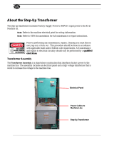
Transformer Assembly........................................................................................................................ 1-6
LED Controller..................................................................................................................................... 1-6
Router.................................................................................................................................................. 1-6
Volume Control Unit............................................................................................................................ 1-7
4-Channel Pre-amplifier ...................................................................................................................... 1-7
1000-Watt Audio Digital Power Amplifier............................................................................................ 1-7
Audio Output Transformers................................................................................................................. 1-7
Bill Acceptor ........................................................................................................................................ 1-7
NiteHAWK Specifications....................................................................................................................... 1-10
Sound System................................................................................................................................... 1-10
Fuses and Circuit Breakers............................................................................................................... 1-10
Lighting.............................................................................................................................................. 1-10
SECTION: 2 INITIAL SET UP AND TESTING................................................................................................ 2-1
Initial Set Up ............................................................................................................................................. 2-1
Testing the Network ............................................................................................................................ 2-1
Calibrating the Touchscreen ............................................................................................................... 2-1
Credit Test........................................................................................................................................... 2-2
Audio Test ......................................................................................................................................... 2-33
Connection Rules ..................................................................................................................................... 2-3
SECTION: 3 SOUND SYSTEM SETUP .......................................................................................................... 3-1
Introduction............................................................................................................................................... 3-1
Extension Speaker Operation .................................................................................................................. 3-1
Selecting Speaker Power......................................................................................................................... 3-3
General Instructions ............................................................................................................................ 3-3
Selection Procedures .......................................................................................................................... 3-3

Table of Contents NiteHAWK Internet Jukebox
iv 22022613 Rev A
Extension Speakers Connected E1 to E7 or T1 to T7.........................................................................3-4
4-Ohm Speakers Connected to Transformer Taps E1 through E6 or T1 through T6 .........................3-5
4-Ohm Speakers Connected to Channel 1 Transformer Taps:...........................................................3-5
4-Ohm Speakers Connected to Channel 2 Transformer Taps:...........................................................3-5
8-Ohm Speakers Connected to Transformer Taps E1 through E6 or T1 through T6 .........................3-6
8-Ohm Speakers Connected to Channel 1 Transformer Taps............................................................3-6
8-Ohm Speakers Connected to Channel 2 Transformer Taps............................................................3-6
Amplifier Overload Check....................................................................................................................3-8
Speaker Synopsis...................................................................................................................................3-18
1000 Watts of RMS Power per Amplifier or 500 Watts per Channel.................................................3-18
SECTION: 4 ADDING MICROPHONES..........................................................................................................4-1
SECTION: 5 LED LIGHTING AND BILL ACCEPTOR....................................................................................5-1
LED Control Assembly (#61182001)...................................................................................................5-1
Features of the LED Control Assembly (#61182001) (Figure 5–1).....................................................5-1
Flash Rate (Speed) of the Perimeter LEDs.........................................................................................5-1
Brightness of the Perimeter and Face Graphic (Panel) LEDs.............................................................5-1
Music Beat Sensitivity for Perimeter LEDs..........................................................................................5-2
LED Flash Mode Setting for Perimeter LEDs (Figure 5–2) .................................................................5-2
Setting Pattern for Perimeter LEDs .....................................................................................................5-2
Bill Acceptor Settings................................................................................................................................5-4
Coinco Vantage Setup.........................................................................................................................5-4
MEI AE2611 Setup ..............................................................................................................................5-6
SECTION: 6 ROUTINE SERVICE ...................................................................................................................6-1
Introduction ...............................................................................................................................................6-1
Preventive Maintenance ...........................................................................................................................6-1
Exterior ................................................................................................................................................6-1
Touchscreen Calibration......................................................................................................................6-2
Hard Drive Replacement .....................................................................................................................6-2
Air Filter ...............................................................................................................................................6-3
SECTION: 7 TROUBLESHOOTING................................................................................................................7-1
Introduction ...............................................................................................................................................7-1
Power Supply Board............................................................................................................................7-2
4-Channel Pre-amplifier.......................................................................................................................7-2
Volume Control Unit ............................................................................................................................7-2
Power Amplifier....................................................................................................................................7-2
Computer Core Assembly ...................................................................................................................7-3
Sequence of Operation.............................................................................................................................7-4
Troubleshooting Charts ..........................................................................................................................7-16
SECTION: 8 PARTS CATALOG .....................................................................................................................8-1
Introduction ...............................................................................................................................................8-2
Catalog Description...................................................................................................................................8-2
Parts List Description................................................................................................................................8-2
Ordering Replacement Parts ....................................................................................................................8-2
Accessory Equipment .............................................................................................................................8-17

NiteHAWK Internet Jukebox Table of Contents
22022613 Rev A v
List of Tables
Table 3–1 – Extension Speaker Worksheet Sheet 1 ................................................................................... 3-4
Table 3–2 – Extension Speaker Worksheet Sheet 2 ................................................................................... 3-5
Table 3–3 – Extension Speaker Worksheet Sheet 3 ................................................................................... 3-6
Table 3–4 – Extension Speaker Worksheet Sheet 4 ................................................................................... 3-7
Table 3–5 – Jukebox Speaker Power ........................................................................................................... 3-7
Table 3–6 – Jukebox Speaker Power (Rock-Ola Floor Models Only) ....................................................... 3-8

Table of Contents NiteHAWK Internet Jukebox
vi 22022613 Rev A
Table of Figures
Figure 1–1 – Installing the Hanger Bracket ......................................................................................................1-4
Figure 1–2 – Reinstalling the Retainer Brackets ..............................................................................................1-5
Figure 1–3 – Major Components ......................................................................................................................1-8
Figure 1–4 – Bottom Panel Filter and Switches ...............................................................................................1-9
Figure 2–1 – Computer Core............................................................................................................................2-2
Figure 2–2 – Calibration Screen.......................................................................................................................2-2
Figure 2–3 – Jukebox User Interface – “1 Credit Plays” Selected ...................................................................2-3
Figure 3–1 – Supported Output Transformer Assemblies................................................................................3-1
Figure 3–2 – Speaker Connections Rowe Floor Models................................................................................3-10
Figure 3–3 – Speaker Connections Rowe Wall-Mounted Model ...................................................................3-12
Figure 3–4 – Speaker Connections Rock-Ola................................................................................................3-14
Figure 3–5 – Audio Output Transformer Wiring Diagram (#40832115) .........................................................3-16
Figure 3–6 – Audio Distribution Assembly Wiring Diagram (70251-A) ..........................................................3-17
Figure 3–7 – External Speakers with Jukebox Speakers Connected to E1 – E7 Rowe Floor Model............3-19
Figure 3–8 – Ten speakers with Jukebox Speakers Connected to E3 – E7 Rowe Floor Model ...................3-20
Figure 3–9 – Low Voltage and 70V Speakers with Jukebox Speakers Connected to
E1 – E7 Rowe Floor Model............................................................................................................................3-21
Figure 3–10 – Ten Speaker Connected to E1 – E7 Rowe Wall-Mounted Model...........................................3-22
Figure 3–11 – Low Voltage and 70V Speaker Connection to E1 – E7 Rowe Wall-Mounted Model..............3-23
Figure 3–12 – External Speaker Connection with Jukebox speakers connected to E1 – E7 Rock-Ola ........3-24
Figure 3–13 – Ten Speakers with Jukebox Speakers Connected to T3–T7 Rock-Ola..................................3-25
Figure 3–14 – Low Voltage and 70V Speakers with Jukebox Speakers Connected to T1-T7 Rock-Ola ......3-26
Figure 3–15– Volume Control Unit .................................................................................................................3-27
Figure 3–16 – Volume Connections Using Existing 3-Wire or 4-Wire Cable 6 Conductor
Modular Wall Jack Radio Shack Model LT-468 Catalog #279-005................................................................3-28
Figure 4–1 – Microphone Connections.............................................................................................................4-1
Figure 4–2 – Paging Microphone Setup Screen ..............................................................................................4-2
Figure 4–3 – VCU Setup Screen......................................................................................................................4-3
Figure 5–1 – LED Control Assembly ................................................................................................................5-3
Figure 5–2 – Program DIP Switches ................................................................................................................5-3
Figure 5–3 – Coinco Vantage DIP Switches ....................................................................................................5-4
Figure 5–4 – Service Mode Button and Diagnostic Indicator LED ...................................................................5-4
Figure 5–5 – Removing the Lower Housing .....................................................................................................5-5
Figure 5–6 – Configuration Settings.................................................................................................................5-5
Figure 5–7 – MEI Bill Acceptor .........................................................................................................................5-6
Figure 6–1 – Calibrate Button...........................................................................................................................6-2
Figure 6–2 – Calibration Screen.......................................................................................................................6-2
Figure 6–3 – Computer Core............................................................................................................................6-2
Figure 6–4 – Filter Removal .............................................................................................................................6-3
Figure 7–1 – NiteHAWK Wiring Diagram (Sheet 1) .........................................................................................7-6
Figure 7–1 – NiteHAWK Wiring Diagram (Sheet 2) .........................................................................................7-7
Figure 7–1 – NiteHAWK Wiring Diagram (Sheet 3) .........................................................................................7-8

NiteHAWK Internet Jukebox Table of Contents
22022613 Rev A vii
Figure 7–1 – NiteHAWK Wiring Diagram (Sheet 4)......................................................................................... 7-9
Figure 7–1 – NiteHAWK Wiring Diagram (Sheet 5)....................................................................................... 7-10
Figure 7–1 – NiteHAWK Wiring Diagram (Sheet 6)....................................................................................... 7-11
Figure 7–1 – NiteHAWK Wiring Diagram (Sheet 7)....................................................................................... 7-12
Figure 7–1 – NiteHAWK Wiring Diagram (Sheet 8)....................................................................................... 7-13
Figure 7–1 – NiteHAWK Computer Core Schematic (Page 1) ...................................................................... 7-14
Figure 7–1 – NiteHAWK Computer Core Schematic (Page 2) ...................................................................... 7-15
Figure 8–1 – Door Assembly (External View).................................................................................................. 8-4
Figure 8–2 – Door Assembly – Internal View................................................................................................... 8-6
Figure 8–3 – Shell Assembly (Internal View)................................................................................................... 8-8
Figure 8–4 – Shell Assembly (Internal View, Left Hand Side)....................................................................... 8-10
Figure 8–5 – Shell Assembly (Internal View, Right Hand Side)..................................................................... 8-11
Figure 8–6 – Computer Core Assembly......................................................................................................... 8-12
Figure 8–7 – Power Supply Assembly ........................................................................................................... 8-13
Figure 8–8 – 4-Channel Pre-Amplifier ........................................................................................................... 8-14
Figure 8–9 – Output Transformer Assembly.................................................................................................. 8-15
Figure 8–10 – Hanger Bracket Assembly ...................................................................................................... 8-16

This page intentionally left blank.

NiteHAWK Internet Jukebox Unpacking & System Description
22022613 Rev A 1-1
Section: 1 Unpacking & System Description
Introduction
The NiteHAWK jukebox is part of a much larger system – the AMI Entertainment network.
This network is a digital platform that delivers music across the Internet to Rowe Jukeboxes
anywhere.
The NiteHAWK jukebox is an Internet-enabled jukebox that allows all the traditional
functions of a jukebox backed by the power of the Internet. This Internet connectivity gives
patrons more features, such as the ability to download “Music On Demand” songs when
their song choice is not already on the jukebox.
NiteHAWK Jukebox Features
General Features:
• Sturdy construction and reliable design
• Conveniently located customer, operator, and service controls
• All major components are modular and easy to replace, if needed
• Computer-controlled digital music
• A 1000-watt amplifier with dual 5-band graphic equalizer
• Song reject
• 300 album and cover art capacity
• Unwanted music categories can be blocked
• Quarter Coin Acceptance
• Bill acceptance of $1, $5, $10, and $20
• Bill Box Capacity of 1000 bills
• Web-based management
• Dynamic Attract mode
• “Music On Demand” song download
• Dynamic search capabilities
• No pause between plays
• Easy to change pricing
• Background music tie-in
• Expandable to 2 or 4 zones
Service Features:
• All servicing can be done from the front of the jukebox
• Modular component construction for easy replacement
• No CD’s to bother with or cumbersome cover art mechanisms
• Complete cash and play audit information
• Password protected Operator Web site
• Access anytime and from anywhere
• Track revenue and usage
• Download new music and other content
• Check system status

Unpacking & System Description NiteHAWK Internet Jukebox
1-2 22022613 Rev A
Unpacking Instructions
This section contains information for unpacking the jukebox and installing it at a location.
The jukebox is shipped with all major components except the Volume Control Unit in place.
Save all tie-down hardware in case the NiteHAWK must be moved to another location.
1. Remove the shipping carton with care: Do not use shipping hooks or sharp tools that
could damage the jukebox cabinet.
2. Remove the plastic bag that covers the jukebox.
3. Carefully inspect the interior and exterior of the jukebox to ensure that no damage
occurred during transit.
If damage is detected, the carrier who delivered the jukebox should be contacted
immediately to examine it. Regardless of the exterior condition of the shipping cartons, the
carrier should be called and notified of damage. Do not destroy packing material or boxes
until the carrier’s agent has examined them.
Damage claims are your responsibility. Do not return damaged merchandise until after your
claim has been established. Once your claim has been established, merchandise may be
returned to your Rowe distributor for repair. The invoice amount for repair charges can then
be collected from the carrier.
Door
Locate the white bag in the coin return on the side of the cabinet. Remove the door key
from the bag and unlock the door. Turn the key clockwise and press in on the door as you
turn the key.
Visual Inspection
Check to be sure that all electrical plugs inside the jukebox are completely seated into their
receptacles.
Handy Case
Locate the Handy Case in a blue plastic envelope. The Handy Case contains a variety of
items, including this jukebox service manual and parts catalog, Volume Control Unit, spare
parts, and fuses. Keep the Handy Case with the jukebox at all times for ready reference.
Warranty Registration Card
A postage-paid Warranty Registration Card is included in this manual. This card should be
filled out and returned to Rowe.

NiteHAWK Internet Jukebox Unpacking & System Description
22022613 Rev A 1-3
Installation Instructions
CAUTION!
NiteHAWK must be solidly fastened to structural members within the supporting wall.
NiteHAWK weighs 180 pounds (82 kg); if it falls, it could cause damage or injury.
CAUTION!
Supplied fasteners (1-1/2” lag screws) are for wood wall stud construction. The
installer must use supplied fasteners, or longer length lag screws.
Installing the Hanger Bracket
The Hanger Bracket is shipped installed to back of the NiteHAWK. Refer to Figure 1–1.
1. Loosen the 2 screws in the slots of both Retainer Brackets. Refer to Figure 1–2.
Slide the Retainer Bracket to the side and remove. Then lower and remove the
Hanger Bracket.
IMPORTANT: Save the Retainer Brackets for later use after the NiteHAWK is
installed.
2. PREFERRED METHOD*: At the installation location, use a level to mark a line that
is exactly level and 66.5" (169 cm) above the floor. This will place the bottom of the
NiteHAWK at 30.80" (78.2 cm) above the floor.
IMPORTANT: This line must be level so that the mounted NiteHAWK will be level.
IMPORTANT: If replacing a WP-100 series CD Box or an NDW-1 Duet Box, use the
level to mark a line that is exactly 4 1/2" directly below the existing holes. This will
allow the use of existing lower holes in the wall and place the NiteHAWK at the same
recommended height.
3. Locate the wall stud locations on the horizontal line. If using the supplied lag screws,
drill 5/32" holes at the mark.
4. Place the Hanger Bracket against the wall. Align the Hanger Bracket holes with the
wall marks and attach with all fasteners.
* In order to comply with the height requirements of the ADA (Americans with
Disabilities Act), this line must be no more than 56.450 inches from the floor.

Unpacking & System Description NiteHAWK Internet Jukebox
1-4 22022613 Rev A
16.000 5.665
5.162
5.615
5.112 8.132 7.868
35.703
FLOOR
30.80
2.700
17.750
66.500*
Figure 1–1 – Installing the Hanger Bracket
Hanger
Bracket

NiteHAWK Internet Jukebox Unpacking & System Description
22022613 Rev A 1-5
Hanging the NiteHAWK on a Bracket
CAUTION!
The NiteHAWK weighs 180 pounds (82 kg) and requires at least two people for
lifting. To see the Hanger Bracket alignment to the holes in the back panel, open the
Main Door.
1. As you lift the NiteHAWK to the Hanger Bracket, look through the opened door to
be sure the keyhole slots of the NiteHAWK Back Panel are aligned with the
spools of the Hanger Bracket.
2. Push the NiteHAWK against wall and lower it onto the spools.
3. While the Door is still opened, visually check that the NiteHAWK Back Panel is
properly seated on the spool slots.
4. Reinstall the Retainer Brackets and tighten the screws to lock the NiteHAWK on
the Hanger Bracket. Refer to Figure 1–2.
Loosen Screws
Hanger Bracket Spool
Loosen Screws Retainer Brackets
Figure 1–2 – Reinstalling the Retainer Brackets

Unpacking & System Description NiteHAWK Internet Jukebox
1-6 22022613 Rev A
Major Components of the NiteHAWK
Figures 1–3 and 1–4 show the major components of the NiteHAWK Jukebox. Take a
minute to familiarize yourself with these components.
Computer Core Assembly
The Computer Core Assembly is the heart of the system and has a removable hard drive
and a single board computer. The hard drive is the only storage in the system and contains
Windows XP Embedded Operating System software, all application software, all music, and
all setup and audit data. The single board computer converts music selections stored on the
hard drive into a stereo signal for the system’s audio components. It connects to the
Internet, the SVGA touchscreen monitor, and the Rowelink modules. It also includes the
coin switch, router reset, fan circuits, bill acceptor, song reject, infrared detector and
amplifier mute.
Touchscreen 19” LCD Monitor
All machine operations are done through the touchscreen monitor. These include viewing
and making selections, displaying the selection being played, displaying pricing and credits,
viewing and changing setup and audit data, and downloading “Music On Demand”
selections.
System Power Supply
The system power supply produces +9 VDC, +12 VDC, +24 VDC, and contains a relay to
switch the jukebox lights, touchscreen monitor, and Bill Acceptor ON or OFF. It has an IEC
320 power inlet, two 6A circuit breakers and two 4A fuses.
Transformer Assembly
The transformer assembly supplies power for the 4-Channel Pre-Amplifier, 1000-Watt Audio
Digital Amplifier, and the system power supply described above.
LED Controller
This module controls the LEDs that illuminate the perimeter lighting on the door and the
door graphics of the jukebox. It provides adjustments for the Brightness, Flash Rate, and
Music Sensitivity along with controls for the patterns used during standby, and separately,
the times when music is playing.
Router
This device provides the interface between the Computer Core Assembly and the
broadband modem or satellite receiver. There is a one-time configuration process to set this
device for your particular Internet Service Provider (ISP). In addition to the port required for
the Computer Core Assembly, there are three other ports provided for other devices.

NiteHAWK Internet Jukebox Unpacking & System Description
22022613 Rev A 1-7
Volume Control Unit
The Volume Control Unit (VCU), a Rowelink module, should be mounted remotely (behind
bar, etc.). The 100-foot modular cable (included) can be connected between the unit and
the green VCU plug on the Computer Core Assembly. It displays and controls the volume of
the amplifier channels and microphones. If an existing 100 foot cable is already in place, you
can use the 3-wire or 4-wire (see Figure 3-16) alternate wiring.
• The POWER button turns the NiteHAWK Jukebox lights, touchscreen monitor and Bill
Acceptor ON or OFF.
• The REJECT button rejects the selection playing.
• The FUTURE button adds credits toward selections (See “Credit Management” in the
Operator Setup Screens Manual).
• The MODE key toggles between channels and microphones.
• The VCU also raises or lowers the volume of the channel(s) or microphone using the UP
DOWN keys. The volume range is 0 to 63. Channel Volume is displayed when the
mode LED is off, and microphone volume is displayed when the mode LED is on.
The CH, MIC, and SINGER LEDs indicate what volume is being displayed. When
adjusting channel volume, if more than one LED is on, it means those channels have the
same volume. All four channels have the same volume when shipped from the factory
(see Section 3 of the included “Network Setup, Jukebox Operation, Operator Setup
Screens” manual for other possible configurations).
4-Channel Pre-amplifier
This Rowelink module transforms audio signals from the Computer Core Assembly,
microphones, and other sound processors/equipment/systems into signals for the Power
Amplifier. It contains Automatic Volume Control (AVC) circuits to adjust for varying
recording levels and tone controls, and 5-band equalizers. All adjustments and options are
programmable via the touchscreen and are retained on the Computer Core Assembly hard
drive (see Section 3 of the included “Network Setup, Jukebox Operation, Operator Setup
Screens” manual for setup information).
1000-Watt Audio Digital Power Amplifier
The 2-channel digital audio power amplifier is rated 1000 watts RMS (500 per channel) into
a 2-ohm load. The full volume output voltage is 32 volts.
The amplifier is protected against overloads and short circuits. Continuous severe
overloads or shorts may shut down the amplifier (or a channel) but will not damage it. If the
overload is removed a signal will reset the amplifier when the next selection plays.
Audio Output Transformers
The output transformers “step up” the power amplifiers output voltage for 70-volt extension
speakers. They also provide screw terminal connections for selecting different power levels
for extension speakers.
Bill Acceptor
The Coinco® Vantage™, with an 1100-bill stacker or MEI® Series 2000 bill acceptor, with a
1000-bill stacker, operates on 120 VAC input power and sends its pulsed credit signals to
the Computer Core.

Unpacking & System Description NiteHAWK Internet Jukebox
1-8 22022613 Rev A
Figure 1–3 – Major Components
Power Transformer
Computer Core
Route
r
Coin Acceptor
Coin Inlet
Bill Accepto
r
Touchscreen
19” LCD Monito
r
LED Controller
LCD Power
Adapter
System Power Supply Audio Output
Transformer
Cabinet Fan
A
ir Filte
r
4-Channel Pre-amplifier
1000 Watt Digital Audio
Output Transformer
/