Page is loading ...

Page 1 of 8
26683851
REV. A
Ecast View B75B Motherboard Upgrade Kit
Kit #26683801
This kit will not support the Ecast View COIM Board. If your View core computer
has the Ecast View COIM board installed you must order the AMI Hardware
conversion Kit # 26683513.
Tools Required
#2 Phillips Head Screwdriver.
Parts Included with this Kit
Item # Part Number Description Quantity
1 40924214 B75B Motherboard 1
2 22219001 SATA Hard Drive (US) 1
3 40980802 Bracket SATA Mounting Adapter 1
4 22132253 Cable HD SATA Power 1
5 22132252 Cable HD SATA/DATA 1
6 34037946 Harness ATX Power Adapter 1
7 22132284 Harness Front Panel View (B75B) 1
8 22132280 Cable Assembly COM to I/O 1
9 80351604 Screws #4-40 x ¼ Phillip (Not Shown) 4
10 ST-06348 Screws #6-32 x ¼ Phillip (Not Shown) 4
These Instructions
Figure 1
Installation Instructions
1
2
3
4
6
5
8
7

Page 2 of 8
26683851
REV. A
Note: Installation of this kit will disable your serial credit card reader (if installed). If you
require a credit card reader, please call AMI Tech Support at 877-ROC-N-ROL to order a
new USB Encrypted Card Reader Kit for your jukebox.
1. Turn the jukebox off and unplug it from the wall outlet.
2. Unplug all the harness connections to the View core computer assembly and remove the
core computer from the jukebox.
3. Remove the Ecast hard drive from the core computer. This hard drive will not be reused.
Please return it to AMI.
4. Disconnect all of the cables from the AMI View I/O board. Route all of the cables thru
the access slots into the core computer chassis. Remove the (4) screws holding the I/O
board and its cover. Remove the (6) screws holding the chassis cover to access the
motherboard.
Figure 2
ECAST HARD
DRIVE
I/O BOARD
ACCESS
SLOTS
CHASSIS
COVER

Page 3 of 8
26683851
REV. A
5. Before installing your B75B Motherboard confirm the “J1” jumper pins 1 and 2 are
shorted if you are converting a 19” touchscreen. If you are converting a 15” Touchscreen
the “J1” jumper pins 2 and 3 on the B75B motherboard must be shorted. See Figure 3.
Figure 3
6. Disconnect the (3) ribbon cables and the IDE hard drive cable, they will not be reused.
Disconnect the 20 pin ATX power supply connector as shown in Figure 4
7. Remove the (4) screws holding the motherboard and the I/O Shield to the core computer
chassis. The motherboard and the I/O Shield will not be reused.
Figure 4
IDE CABLE
RIBBON
CABLES
20 PIN
POWER
CONNECTOR
MOTHERBOARD
J1 HEADER

Page 4 of 8
26683851
REV. A
8. Position the new I/O Shield into the computer chassis and install the new B75B motherboard
(Item #1) using the (4) screws removed in step # 7.
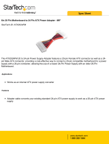
9. Locate the Front Panel Harness (Item #7) labeled 22132284. Connect the (10) pin housing to
the “F-Panel” header of the B75B motherboard. See Figure 5.
10. Locate the COM to I/O cable (Item #8) labeled 22132280. Connect the (10) pin housing to
the “COM1” header of the B75B motherboard. See Figure 5.
11. Connect the 20 pin ATX power supply connector to the B75B motherboard. Locate the ATX
(4) Pin Adapter Harness labeled 34037946 (Item #11). Connect the (4) pin female housing to
the (4) pin male housing of the ATX power supply. Connect the (4) pin male housing to the
B75B motherboard as shown in Figure 5.
12. Connect the SATA/DATA Hard Drive cable (Item #5) to the SATA connector as shown in
Figure 5. Connect the HD SATA Power Cable (Item #4) to the remaining (4) pin ATX power
supply connector.
Figure 5
COM1
HEADER
F PANEL
HEADER
20 PIN ATX
CONNECTOR
4 PIN ATX
CONNECTOR
SATA/DATA
CONNECTOR

Page 5 of 8
26683851
REV. A
13. Carefully route the SATA/DATA and SATA power cables from the motherboard thru the
access slots for the hard drive. Route the remaining (4) pin ATX power cable, COM to I/O
and the front panel harnesses thru the access slots for the AMI View I/O board.
14. Check harness routing for pinch points or fan interference. Install the computer core cover
and AMI I/O board cover with the same screws removed in Step # 4.
15. Secure the SATA hard drive 22219001 (Item #2) to the SATA Mounting Adapter Bracket
40980802 (Item #3) using the (4) #4-40 x 1/4 screws 80351604 (Item #9) as shown in Figure
6.
Figure 6
16. Install the adapter bracket and hard drive assembly to the Computer Core with (4) #6-32 x ¼
screws ST-06348 (Item #10) as shown in Figure 7. Connect the SATA power cable and the
SATA/Data Cable to the hard drive as shown in Figure 7.
Figure 7
HARD
DRIVE
#4-40 ¼ SCREWS
(TWO ON
EITHER SIDE)
ADAPTOR
BRACKET
SATA/DATA
AND POWER
CONNECTIONS
HARD
DRIVE
ASSEMBLY

Page 6 of 8
26683851
REV. A
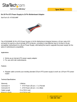
17. Connect the (4) pin ATX power supply housing to the header labeled “CN1 Power” on the
I/O Board. Connect the (20) pin housing of the front panel harness to the header labeled
“CN5 Core Control” on the I/O Board. Connect the (10) pin COM to I/O ribbon cable to the
header labeled “CN6 RS232” on the I/O Board as shown in Figure 8.
Figure 8
18. Double check that all harnesses are properly connected and all mounting screws are tight.
Reinstall the Computer Core back into the jukebox. Reconnect all harnesses to the AMI
View I/O board and touch screen cables removed in Step #4.
Power up Testing
19. Plug the jukebox back into the wall outlet then power up the jukebox to ensure the jukebox
UI comes up. This will take some time and may include one or more reboots.
20. In order for the jukebox to connect to the AMI network, the MAC address of the computer
core must be entered into the AMI database and the jukebox will have to be added to your
operating contract. This will require a phone call to the AMI Tech Support line, 1-877-ROC-
N-ROL (1-877-762-6765).
21. The MAC address is found on a Service Mode screen.
22. If the jukebox is not in the Service Mode, push the Activate Service Screen button on the
core computer I/O board.
23. Push the Calibrate Touch Screen button and calibrate the touch screen.
24. Touch Diagnostics then touch System Information. The MAC address will be displayed in
the third block down from the top right.
ATX POWER
FRONT
PANEL
COM to I/O

Page 7 of 8
26683851
REV. A
25. To help the AMI Tech Support technician configure your jukebox in the AMI system, please
have the jukebox model and serial number along with the MAC address when you call.
26. After Tech Support has entered the MAC address of the jukebox, you will need to enter the
Trigger Code.
27. From the main menu in the Service Mode, touch System Setup then touch Enable/Extend
Features.
28. Using the on-screen keypad, enter the trigger code found on the Trigger Code Card then
touch the Send Code button.
29. In order for the coin switches to work properly, you will have to adjust the coin setup on the
Cash Management – Song Pricing screen. For View kits that were installed in old Rowe CD
jukeboxes with 4 coin acceptors, use the coin setup shown in Figure 3. Otherwise, use the
Diagnostics – Credit Devices screen to discover which inputs are used for which coins then
configure the coin setup accordingly.
Figure 9

Page 8 of 8
26683851
REV. A
/