Page is loading ...

Z-WORLD SINGLE BOARD COMPUTER
BL2500
EMBEDDED PLC
USER’S MANUAL

COPYRIGHT
EMBEDDED PLC BL2500 User’s Manual y Part Number: TD-0002-4
© 2006 OEM Technology Solutions Pty Ltd. All rights reserved worldwide. This document is the property of
OEM Technology Solutions Pty Ltd and may not be copied, used or disclosed in whole or in part except with
the prior written permission of OEM Technology Solutions Pty Ltd or if it has been furnished under contract
with another party, as specified in that contract. The copyright and the foregoing restriction on copying, use
and disclosure extend to all media in which this information may be embodied. No liability is accepted for
errors or omissions in this document. The information contained within this document is subject to change
without notice.
TRADEMARKS
EMBEDDED PLC is a registered trademark of OEM Technology Solutions Pty Ltd.
Microsoft, Windows, Windows XP, Windows 2000 and Windows NT are registered trademarks of Microsoft
Corporation in the United States and/or other countries.
ISaGRAF is a registered trademark of ICS Triplex ISaGRAF Inc.
Rabbit and Rabbit 3000 are registered trademarks of Rabbit Semiconductor.
RabbitNet is a trademark of Z-World Inc.
Dynamic C is a registered trademark of Z-World Inc.
Indusoft is a registered trademark of Indusoft Ltd.
All other brand or product names are trademarks or registered trademarks of their respective holders.
NOTICE TO USERS
When a system failure may cause serious consequences, protecting life and property against such
consequences with a back-up system or safety device is essential. The buyer agrees that protection against
consequences resulting in system failure is the buyer’s responsibility.
This device is not approved for life support or medical systems.
OEM Technology Solutions
Unit 13, 82 Reserve Road
Artarmon NSW 2064
AUSTRALIA
Telephone: +61 (2) 9966-9424
Fax: +61 (2) 9966-9429
www.oem.net.au

EMBEDDED PLC BL2500 User’s Manual
OEM Technology Solutions Page i
TABLE OF CONTENTS
1. INTRODUCTION.................................................................................................................................1
1.1 WHAT IS EMBEDDED PLC?....................................................................................................1
1.2 BL2500 OVERVIEW .................................................................................................................1
1.3 ABOUT THIS MANUAL ............................................................................................................2
1.4 EMBEDDED PLC APPLICATION KIT ......................................................................................3
1.5 TEXT CONVENTIONS .............................................................................................................3
1.6 WINDOWS CONVENTIONS ....................................................................................................3
1.7 REFERENCE DOCUMENTS....................................................................................................4
1.8 ABBREVIATIONS AND TERMINOLOGY.................................................................................4
2. GETTING STARTED ..........................................................................................................................7
2.1 INTRODUCTION ......................................................................................................................7
2.2 SOFTWARE INSTALLATION...................................................................................................7
2.2.1 Installing ISaGRAF Workbench V3.50 ......................................................................8
2.2.2 Installing EMBEDDED PLC Board Support Package (BSP) for BL2500 ..................8
2.3 LICENSING THE ISAGRAF WORKBENCH.............................................................................8
2.3.1 Adding the software license.......................................................................................9
2.3.2 Adding a hardware license (optional) ........................................................................9
2.4 BL2500 CONNECTIONS ........................................................................................................10
2.4.1 Connect a Power Supply .........................................................................................10
2.4.2 Connect an Ethernet Cable .....................................................................................10
2.4.3 Connect an RS232 Cable (optional)........................................................................12
2.5 RUNNING A SAMPLE APPLICATION ...................................................................................12
2.6 WHERE DO I GO FROM HERE?...........................................................................................14
3. RUNNING SAMPLE APPLICATIONS..............................................................................................15
3.1 RUNNING APPLICATIONS IN SIMULATION MODE ............................................................15
3.2 RUNNING APPLICATIONS THAT USE INTERNAL VARIABLES ONLY ..............................17
3.3 RUNNING APPLICATIONS THAT USE BL2500 INPUTS AND OUTPUTS ..........................18
3.3.1 Creating I/O connectors...........................................................................................18
3.3.2 Downloading and running the ISaGRAF application...............................................19
3.4 CREATING A NEW PLC APPLICATION................................................................................20
3.4.1 Using Function Blocks Diagrams ............................................................................20
3.4.2 Using Quick Ladder Diagrams ................................................................................25
3.4.3 Using Structured Text..............................................................................................27
3.4.4 Using Instruction List ...............................................................................................29
3.4.5 Using Sequential Function Chart.............................................................................30
3.4.6 Using Flow Chart .....................................................................................................33
4. HARDWARE REFERENCE..............................................................................................................35
4.1 DIGITAL INPUTS....................................................................................................................35
4.2 DIGITAL OUTPUTS................................................................................................................36
4.3 ANALOG INPUT .....................................................................................................................36
4.4 ANALOG OUTPUT .................................................................................................................37
4.5 COMMUNICATION INTERFACES.........................................................................................38
4.5.1 Serial Ports ..............................................................................................................38
4.5.2 Ethernet Port ...........................................................................................................39
4.6 LED INDICATORS..................................................................................................................40
5. SOFTWARE REFERENCE ..............................................................................................................41

EMBEDDED PLC BL2500 User’s Manual
OEM Technology Solutions Page ii
5.1 MORE ABOUT ISAGRAF ...................................................................................................... 41
5.1.1 Project Manager ..................................................................................................... 41
5.1.2 Program Manager................................................................................................... 41
5.1.3 Variable Definition................................................................................................... 41
5.1.4 Functional Module Programming............................................................................ 41
5.1.5 IEC 61131-3 Language Editors .............................................................................. 42
5.1.6 Flow Chart Editor .................................................................................................... 42
5.1.7 Document Generator .............................................................................................. 42
5.1.8 Simulation ............................................................................................................... 42
5.2 ISAGRAF SOFTWARE REFERENCE................................................................................... 43
5.2.1 I/O Boards............................................................................................................... 43
5.2.2 ISaGRAF C Functions ............................................................................................ 45
5.2.3 ISaGRAF C Function Blocks .................................................................................. 46
6. LOADING OR UPGRADING THE FIRMWARE KERNEL .............................................................. 48
6.1 INTRODUCTION....................................................................................................................48
6.1.1 Installing EMBEDDED PLC Utility .......................................................................... 48
6.1.2 Connecting to the BL2500 ...................................................................................... 48
6.1.3 Loading and licensing the Firmware Kernel ........................................................... 49
6.1.4 Configuring the Firmware Kernel............................................................................ 50
6.2 EMBEDDED PLC UTILITY SOFTWARE REFERENCE ....................................................... 51
6.2.1 Menu Commands ................................................................................................... 51
6.2.2 Loading Shortcuts................................................................................................... 53
7. FAQ AND TROUBLESHOOTING ................................................................................................... 54
7.1 KNOWN ISSUES ................................................................................................................... 54
7.1.1 BL2500 with Rabbit 3000 Microprocessor Revision 0 (IL1T) ................................. 54
7.1.2 BL2500 with Large Sector Flash ............................................................................ 54
7.1.3 ISaGRAF Floating Point Arithmetic ........................................................................ 54
7.1.4 Reading/writing 32-bit integer/real analog variables via Modbus ........................... 54
7.2 FAQ ........................................................................................................................................ 55
7.3 TROUBLESHOOTING ........................................................................................................... 57
7.3.1 Common Errors ...................................................................................................... 57
7.3.2 Before Contacting Technical Support..................................................................... 58
8. SPECIFICATIONS ........................................................................................................................... 60
8.1 ELECTRICAL AND MECHANICAL SPECIFICATIONS ........................................................ 60
9. ABOUT INDUSOFT ......................................................................................................................... 62
9.1 USING INDUSOFT WEB STUDIO WITH EMBEDDED PLC................................................. 62

EMBEDDED PLC BL2500 User’s Manual
OEM Technology Solutions Page iii
LIST OF TABLES
Table 1: Main Features of the EMBEDDED PLC Firmware Kernel V1.04 on the BL2500 ...........................2
Table 2: EMBEDDED PLC BL2500 Serial Port Configuration ....................................................................38
Table 3: BL2500 Electrical, Mechanical and Environmental Specifications................................................61
LIST OF FIGURES
Figure 1: Power Supply Connection............................................................................................................10
Figure 2: Ethernet connections ...................................................................................................................11
Figure 3: PC <-> BL2500 RS232 connection..............................................................................................12
Figure 4: BL2500 Pinouts............................................................................................................................35
Figure 5: BL2500 Digital Inputs (Pull-up factory default).............................................................................36
Figure 6: BL2500 Digital Outputs ................................................................................................................36
Figure 7: Schematic Diagram of the A/D Converter....................................................................................37
Figure 8: Schematic Diagram of D/A Converters ........................................................................................37
Figure 9: BL2500 Multidrop Network...........................................................................................................39
Figure 10: RS485 Termination and Bias Resistors .....................................................................................39
Figure 11: RJ-45 Ethernet Port Pinout ........................................................................................................39
Figure 12: Programming Cable Connection................................................................................................49
Figure 13: BL2500 Dimensions ...................................................................................................................60

EMBEDDED PLC BL2500 User’s Manual
OEM Technology Solutions Page iv
This page is intentionally left blank

EMBEDDED PLC BL2500 User’s Manual Introduction
OEM Technology Solutions Page 1
1. INTRODUCTION
1.1 WHAT IS EMBEDDED PLC?
The EMBEDDED PLC system turns a Rabbit-based controller, such as the Coyote BL2500 Single-Board-
Computer (SBC), into a high performance and yet inexpensive Programmable Logic Controller (PLC).
The Target PLC can be programmed using the
EMBEDDED PLC – ISaGRAF® Workbench in any of the
standardized automation control programming languages IEC 61131-3:
• Sequential Function Chart (SFC)
• Function Block Diagram (FBD)
• Ladder Diagram (LD)
• Structured Text (ST)
• Instruction List (IL)
EMBEDDED PLC – ISaGRAF Workbench becomes an alternative to Dynamic C to program Rabbit-based
controllers.
The
EMBEDDED PLC system consists of two parts:
• The Target PLC: A SBC BL2500 powered with the RabbitCore® module RCM3200 (Rabbit 3000
microprocessor, 44.2 MHz clock speed, 512K Flash, 256K Battery-backed SRAM, 512K Fast SRAM
and 10/100BaseT) and loaded with the
EMBEDDED PLC Firmware Kernel (or refer to as the Kernel).
The Firmware Kernel is distributed as a .bin
file which is loaded to the Target through the
EMBEDDED PLC Utility. The Kernel runs the
PLC application in a loop (reading inputs →
evaluate the logic → updating outputs) and
also provides the communication interface
between the Target and the Workbench.
• The ISaGRAF Workbench: The Workbench
provides a complete PLC programming
environment, including an editor for each of
the PLC programming languages,
downloading PLC application to the target,
simulation, program-debugging tools and
on-line monitoring of the PLC application.
1.2 BL2500 OVERVIEW
The BL2500 is an advanced Single Board Computer that incorporates flash memory, SRAM, digital I/O
ports, A/D converter input, D/A converter outputs, RS232/RS485 ports and Ethernet interface (10/100
Mbps). The BL2500 SBC gives PLC designers extremely low-cost embedded control for high-volume
applications such as product control, factory equipment control, access control, HVAC and vending
machines.
The BL2500’s compact board size of 100 x 100 mm is easily mountable in standard 100 mm DIN rail
trays. External connections via polarized locking industry standard Molex® type connectors enable rapid
assembly with wire harnesses. These connectors also provide dependable cable harness connectivity to
I/O.
Main features of the
EMBEDDED PLC Firmware Kernel running on the BL2500 Target PLC, are shown in
Table 1.

EMBEDDED PLC BL2500 User’s Manual Introduction
OEM Technology Solutions Page 2
Table 1: Main Features of the EMBEDDED PLC Firmware Kernel V1.04 on the BL2500
Kernel filename
BL2500C_V1.04_3-0231H.bin
SBC model supported
BL2500 with Rabbit core module RCM3200 (10/100BaseT, 512K Flash, 256K +
512K SRAM, 44.2 MHz clock speed). Z-World P/N: 101-0602
I/Os supported
- 16 Digital Inputs
- 8 Digital Outputs
- 1 Analog Input (connected through AD0): 10 bits resolution, 0 – 3.3 V
- 1 Analog Output (connected through DA1): 10 bits resolution, 0 – 3.3 V
Communications
Modbus RTU over TCP/IP using static IP address
Modbus RTU over RS232 (using serial port E) or RS485 (using serial port D):
- Baud rate: 19200, 9600, 4800, 2400, 1200 or 600 (configurable through
EMBEDDED PLC Utility)
- Parity: None
- Data bits: 8
- Stop bits: 1
- Flow Control: None
Minimum polling period time is 1 cycle duration for Modbus TCP and 2 x cycle
duration for Modbus RTU over RS232/RS485. Cycle duration corresponds to the
time that kernel executes one cycle (read inputs → execute logic → update
outputs)
Performance
- Digital Input scan time is approx. 200 µs.
- Analog Input scan time is approx. 83 ms.
- Digital Output update time is approx. 30 µs per output.
- Analog Output update time is approx. 120 µs.
- Boolean instruction execution time is approx. 30 µs.
- Program execution overhead is approx. 100 µs per program.
Memory Space
Maximum size of ISaGRAF application database is 50000 bytes.
Size of ISaGRAF real-time database (holds variables, SFC engine data, C function
and function blocks data) is 10000 bytes.
Free root memory on the BL2500 is approx. 9000 bytes.
EMBEDDED PLC firmware kernel total code size is approx. 260000 bytes.
ISaGRAF V3.50 features
not supported by
EMBEDDED PLC
- On-line modifications. This feature enables the user to modify the application
while the process is running.
- Uploading application stored in the target.
1.3 ABOUT THIS MANUAL
This manual provides instructions for installing, testing, configuring and interconnecting the Z-World SBC
BL2500 running the
EMBEDDED PLC Firmware Kernel. Instructions are also provided for using the
ISaGRAF Workbench.
This User’s Manual is divided into the following chapters:
• This chapter provides and overview of the
EMBEDDED PLC and information about this publication such
as conventions used and reference documents.
• Chapter 2, Getting Started: Explains how to install the different
EMBEDDED PLC products and run a
sample application.
• Chapter 3, Running Sample Applications: Provides instructions how to run the different types of
sample applications and also how to create a PLC application using the ISaGRAF Workbench.
• Chapter 4, Hardware Reference: Provides a detailed description of the I/Os and communication ports
present in the SBC BL2500 and how to configure them in order to work with
EMBEDDED PLC.

EMBEDDED PLC BL2500 User’s Manual Introduction
OEM Technology Solutions Page 3
• Chapter 5, Software Reference: Provides an overview of the ISaGRAF Workbench functionalities and
detailed description of the ISaGRAF library elements (I/O boards software configuration, C functions
and C function blocks) available from the ISaGRAF Workbench.
• Chapter 6, Using
EMBEDDED PLC Utility: Detailed description of the EMBEDDED PLC Utility.
• Chapter 7, FAQ and Troubleshooting: Describes the known issues with this release, frequently asked
questions and troubleshooting.
• Chapter 8, Specifications: Describes the electrical, mechanical and environmental specifications of
the BL2500.
• Chapter 9, About Indusoft: A brief description of Indusoft Web Studio and how can be used in
conjunction with
EMBEDDED PLC.
1.4 EMBEDDED PLC APPLICATION KIT
The EMBEDDED PLC BL2500 Application Kit contains the hardware and software needed to use the SBC
BL2500 with EMBEDDED PLC system. It contains:
• BL2500 Single Board Computer with Ethernet capability and pre-loaded with the
EMBEDDED PLC
Firmware Kernel.
• 1.27mm programming cable.
• Ethernet crossover cable.
•
EMBEDDED PLC BL2500 CD-ROM, with complete product documentation on disk.
•
EMBEDDED PLC – ISaGRAF V3.50 Workbench License Registration form.
• Getting Started instructions.
1.5 TEXT CONVENTIONS
This manual uses special formatting to help you quickly identify certain items, as follows:
• Titles, labels, and new terms are indicated using italic text.
• File names, messages and screen text are indicated using bold, courier text (for example,
C:\OEMTech\Install.exe).
• Variables and information you must provide are indicated using bold, italicized text enclosed in < and
> brackets (for example, run the <driver name>.exe file indicates you must provide a driver name).
• Buttons, menu options and keyboard key are indicated in bold.
• Text requiring special emphasis is in bold italic.
• Some information is segregated into Note and Caution boxes as follows:
¾
" Notes provide supplemental information related to the surrounding text, usually the text just
preceding the note.
¾
, Caution provides information necessary to prevent damage or problems.
1.6 WINDOWS CONVENTIONS
This manual uses the following Windows conventions:
• Dialog boxes (or dialogs) are windows that allow you to enter information.
• Text boxes (or fields) are areas in dialogs where you can type in text.
• Radio buttons are white circles in which a black dot appears or disappears when you click on the
button. Typically, the black dot indicates that the option or function is enabled (active). The absence
of a black dot indicates the option or function is disabled (inactive).

EMBEDDED PLC BL2500 User’s Manual Introduction
OEM Technology Solutions Page 4
• Check-boxes are white squares in which a check appears or disappears when you click on it with the
cursor. Typically, the check indicates that the option or function is enabled (active). The absence of a
check indicates the option or function is disabled (inactive).
• Buttons are icons in boxes that appear “pressed” when you click on them.
• Lists are panes (white boxes) in windows or dialog boxes containing two or more selectable options.
• Combo-boxes have arrows that, when clicked, show part or all of an otherwise concealed list.
"
Note:
The dialogs and procedures described in this manual are valid for Windows 2000 and XP.
Some terms may vary according to the operating system (type, language and version) you
are using.
1.7 REFERENCE DOCUMENTS
[1] 019-0120 · 041215-H – Coyote (BL2500) C-Programmable Single-Board Computer with Ethernet
User's Manual, 2002-2004 Z-World Inc.
[2] ISaGRAF Version 3.5 User’s Guide, 1994 – 2004 ICS Triplex ISaGRAF Inc.
[3] 019-0108 · 050610-P - Rabbit® 3000 Microprocessor User's Manual, 2002-2005 Rabbit
Semiconductor.
1.8 ABBREVIATIONS AND TERMINOLOGY
The following abbreviations are terms used throughout the document.
Term Description
A/D Analog to Digital
BSP Board Support Package
D/A Digital to Analog
DDE Dynamic Data Exchange
FAQ Frequently Asked Questions
FBD Function Block Diagram
FC Flow Chart
HMI Human Machine Interface
HVAC Heating, Ventilation and Air-Conditioning. This is sometimes referred to as climate control.
I/O Input/Output
IL Instruction List
IWS Indusoft Web Studio
LAN Local Area Network
LD Ladder Diagram
LED Light Emitting Diode
ODBC Open Database Connectivity
OPC OLE (Object Linking and Embedding) for Process Control
PC Personal Computer
PLC Programmable Logic Controller
RAM Random Access Memory
SBC Single Board Computer
SCADA Supervisory Control And Data Acquisition
SFC Sequential Function Chart

EMBEDDED PLC BL2500 User’s Manual Introduction
OEM Technology Solutions Page 5
SRAM Static Random Access Memory
ST Structured Text
TCP/IP Transport Control Protocol/Internet Protocol
USB Universal Serial Bus

EMBEDDED PLC BL2500 User’s Manual Introduction
OEM Technology Solutions Page 6
This page is intentionally left blank

EMBEDDED PLC BL2500 User’s Manual Getting Started
OEM Technology Solutions Page 7
2. GETTING STARTED
2.1 INTRODUCTION
The EMBEDDED PLC Application Kit provides all the necessary tools to program the Z-World SBC BL2500
(Coyote) via the ISaGRAF Soft Logic package. This chapter will help you to quickly install the necessary
software to run a PLC sample application on the BL2500 target using the ISaGRAF Workbench. This
chapter contains also important information about licensing your product.
To run the
EMBEDDED PLC software products it is required to have a Personal Computer (PC) with at least
a 133-MHz processor (550-MHz or faster processor is recommended). This PC will be referred as the
Host. The PC must have the following hardware and software configuration:
• Windows 2000 or XP operating system
• 128 MB of RAM required; 256 MB or more recommended
• 1.25 to 2 GB of available hard-disk space
• CD-ROM or DVD-ROM drive
• VGA or hardware that supports console redirection required; Super VGA supporting 800 x 600 or
higher-resolution monitor recommended
• 1 serial port (COM1 – COM4)
• Ethernet card
"
Note:
The EMBEDDED PLC Application Kit comes with one Z-World SBC BL2500 pre-loaded with the
EMBEDDED PLC Firmware Kernel. If you require to load the Firmware Kernel to another BL2500
or to upgrade the current one, go to Chapter 6, which describes in detail the installation of the
additional software and how to load or upgrade the
EMBEDDED PLC Firmware Kernel to the
Target.
2.2 SOFTWARE INSTALLATION
The EMBEDDED PLC CD-ROM contains the following software:
• ISaGRAF_V3.50:
EMBEDDED PLC – ISaGRAF V3.50 Workbench installer. This particular installation
is intended to work in stand-alone mode or only with
EMBEDDED PLC Rabbit-based targets. After
installation of the Workbench, the software runs in a trial mode for 30 days. After period expires,
license is required.
• BL2500C_BSP_V1.04_9-0003-006:
EMBEDDED PLC Board Support Package (BSP) for the SBC
BL2500. It contains the
EMBEDDED PLC BL2500 Firmware Kernel and the ISaGRAF I/O boards and
sample files to be installed in the ISaGRAF directory.
• EmbeddedPLCUtility_V1.03_3-0237G: Microsoft Windows Installer of the
EMBEDDED PLC Utility.
The
EMBEDDED PLC Utility allows you to load or upgrade the EMBEDDED PLC Firmware Kernel to a
Rabbit-based Target. The installation of this software is optional and is described in Chapter 6.
These software products can also be downloaded (in ZIP format) from the OEM Technology Solutions
website www.oem.net.au
.

EMBEDDED PLC BL2500 User’s Manual Getting Started
OEM Technology Solutions Page 8
2.2.1 Installing ISaGRAF Workbench V3.50
Use the following procedure to install the EMBEDDED PLC - ISaGRAF Workbench V3.50 from the CD-
ROM:
1. Insert the CD-ROM and open the ISaGRAF_V3.50 folder.
2. Double-click on ISAGRAF.EXE to launch the ISaGRAF installation wizard. Follow the instructions
provided by the wizard to proceed with the installation.
"
Note:
It is recommended that the ISaGRAF Workbench be installed on a new directory to avoid
confusing files with files from other ISaGRAF versions.
3. Once all the ISaGRAF files have been copied, the following group is added to your Programs group:
2.2.2 Installing EMBEDDED PLC Board Support Package (BSP) for BL2500
Use the following procedure to install EMBEDDED PLC BSP for BL2500 from the CD-ROM:
1. Go to BL2500C_BSP_V1.04_9-0003-006 folder located in the root directory of the CD-ROM.
2. Open the ISaGRAF folder and double-click on INSTALL.EXE to launch the ISaGRAF installation
wizard. Enter the location where the ISaGRAF Workbench was installed (default C:\ISAWIN) and
press Install. The installation wizard will update the ISaGRAF main directory with the I/O boards, C
functions, C function blocks and sample applications for the
EMBEDDED PLC BL2500 target.
2.3 LICENSING THE ISAGRAF WORKBENCH
The ISaGRAF V3.50 Workbench you just installed runs for a trial period of 30-days before requiring
licensing. When not licensed, you can not create, modify or export IEC programs to a library, or export
variables to ASCII text file.
You can license ISaGRAF using either hardware or software license. When using a hardware license, a
dongle which you place on the parallel or USB port of your PC is delivered pre-programmed with the
selected feature set. When using software license, you need to obtain a set of registration keys.
The software license is specific to a PC (hardware configuration and Operating System). Therefore if you
re-install the Operating System and then re-install ISaGRAF Workbench a new software license will be
required. However, it is possible to transfer a software license from one PC to another. Section A.1.2.2 of
the ISaGRAF User’s Manual (See [2]) and the License Manager on-line help describe in detail how to
transfer a software license.
The
EMBEDDED PLC Application Kit entitles you to a 32 I/O points software license. To obtain the software
license follow these instructions:
3. Open the ISaGRAF License Manager (Start menu
→ Programs → ISaGRAF 3.5 → Licensing). On
the Available Components select ISaGRAF 3
Software License and press Add button. Click
Option 32 on Number of IO Variables box and
press OK button. The Setup Code SET: WDX32-
WDE15 will be displayed in the Setup Code box.

EMBEDDED PLC BL2500 User’s Manual Getting Started
OEM Technology Solutions Page 9
4. If you have access to the Internet and have an e-mail account:
a) Press Proceed… button. A new mail message of your default e-mail client (such as Microsoft
Outlook) will be displayed. Fill out the information on the message body: Contact details and
Workbench Serial Number (located on the License Registration Form). Once you have filled out
all the information, send the e-mail to [email protected]
. The e-mail client application must be
running before pressing Proceed… button.
b) Alternatively, if instead of e-mail client (such as Microsoft Outlook) you use web-based email or a
command line e-mail (such as pine), compose manually a new message indicating the
Workbench Serial Number that appears in the License Registration Form, User Code 1 and 2,
and Contact details, and send it to [email protected]
.
5. Alternatively, if you do not have an e-mail address or access to the Internet, copy the User Code 1
and User Code 2 into the ISaGRAF License Registration Form that comes in the Application Kit
and send the completed form to OEM Technology Solutions by fax (Fax Number: +61 2 9966 9429).
6. OEM Technology Solutions will send you the ISaGRAF software license within two business days of
receiving the completed Form. Press Close button to close the License Manager.
2.3.1 Adding the software license
The ISaGRAF software license consists of two sets of 4 Registration Keys. Upon reception of the
Registration Keys, open License Manager and follow these instructions:
1. On the Available Components select ISaGRAF 3 Software License and press Add button. Select
the purchased number of I/O points to license (32 if you purchased the
EMBEDDED PLC Application
Kit) and press OK button.
2. Enter the first set of Registration Keys and press
Register button. Setup Code will change to SET:
WDE15. Enter the second set of Registration
Keys and press Register button again. In the
Selected Components ISaGRAF 3 Software
License will be displayed as Active. Press
Close button to close the License Manager.
Congratulations! Your ISaGRAF Workbench is
now licensed.
"
Note:
If you want to purchase a hardware license or upgrade your current software license, please
contact OEM Technology Solutions ([email protected]
) for pricing information and payment
options. When you purchase a software license it is very important to include the following
information in your Purchase Order:
• Setup Code, User Code 1 and User Code 2.
To obtain these codes open the ISaGRAF License Manager (Start menu → Programs →
ISaGRAF 3.5 → Licensing). On the Available Components select ISaGRAF 3 Software
License and press Add button. Select the desired number of I/O points to license (128, 256
or Unlimited) and press OK button. The Setup and User codes appear on the License
Manager window. If you press Proceed… button, a new e-mail message window is displayed
(if you have an e-mail client running such as Microsoft Outlook). You can fill out the required
information and send that e-mail to obtain license pricing and payment information.
• Contact details (Company, Name, Address, Telephone, Fax and e-mail).
2.3.2 Adding a hardware license (optional)
When using a hardware license (dongle) on Windows 2000/XP systems, you must install the Sentinel
driver in order for the dongle to be seen.

EMBEDDED PLC BL2500 User’s Manual Getting Started
OEM Technology Solutions Page 10
Open the ISaGRAF_V3.50\Sentinel folder (located in the root directory of the CD-ROM) and double-
click on Setup.exe. Follow the on-screen instructions to install the driver. After the installation is
completed, connect the dongle to a parallel or USB port and open the License Manager (Start menu →
Programs → ISaGRAF 3.5 → Licensing). On the Selected Components list, the ISaGRAF 3 Hardware
license will be shown active.
2.4 BL2500 CONNECTIONS
2.4.1 Connect a Power Supply
1. Connect the AC adapter to header J2 on the BL2500 as shown in Figure 1. Match the friction lock tab
on the friction-lock connector to the back of header J2 on the BL2500 as shown. The friction-lock
connector will only fit one way. Plug in the AC adapter.
Application Kits sold outside North America or Australia include a friction-lock connector that can be
connected to header J2 on the BL2500. Connect the leads from your power supply to the friction-lock
connector to preserve the polarity indicated in the figure. The power supply should deliver 8 – 40 VDC
at 500 mA.
Figure 1: Power Supply Connection
2. Plug the AC Adapter. DS1 (yellow) and DS2 (red) LEDs indicate the Firmware Kernel status after the
board has been powered up. If after 10 seconds DS2 (red) is turned off and DS1 (yellow) starts
blinking, the Firmware Kernel is licensed and active.
If DS2 (red) remains turned on during more than 10 seconds, it indicates that Kernel requires
licensing. If DS1 and DS2 are off after powered-up, it indicates that the board has no EMBEDDED
PLC Firmware Kernel loaded. In both cases, contact your local distributor.
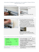
2.4.2 Connect an Ethernet Cable
The BL2500 that comes in the EMBEDDED PLC Application Kit has the Firmware Kernel loaded, licensed
and configured. The default factory configuration is:
Modbus Slave Number = 1
Use Modbus TCP
IP Address = 192.168.1.100

EMBEDDED PLC BL2500 User’s Manual Getting Started
OEM Technology Solutions Page 11
Netmask = 255.0.0.0
Default gateway = 192.168.1.1
If you want to change the default values, go to section 6.1.4 for instructions how to change the
configuration of the Target PLC. The following instructions will guide you on how to connect the Target
PLC to the Workbench using TCP/IP.
There are two ways of connecting the Target PLC to your PC via Ethernet (see Figure 2):
• Using a crossover Ethernet cable (provided in the
EMBEDDED PLC Application Kit) to connect directly
the Target PLC to your PC; or,
• If your PC is currently connected to an Ethernet hub, use a straight-through Ethernet cable (not
provided in the
EMBEDDED PLC Application Kit) to establish an Ethernet connection to the BL2500
from the hub.
Figure 2: Ethernet connections
When your PC is connected directly to the BL2500 via an Ethernet connection, you need to set (or
change) the TCP/IP parameters of your computer in order to establish a proper connection with the
BL2500. If you require changing the TCP/IP configuration of the BL2500, go to section 6.1.4 for
instructions how to change the configuration of the Target PLC.
To configure your PC with an IP address and netmask suitable for establishing a TCP/IP connection with
a pre-configured BL2500 Target PLC, follow these instructions (you might need Administrator privileges
to perform these steps):
1. Go to Control Panel (Start button → Settings → Control Panel) and
start Network Connections.
2. Select Local Area Connection and choose Properties (File menu →
Properties).
3. Select Internet Protocol (TCP/IP) and press Properties button.
4. Click on Use the following IP Address and fill in the following fields:
5. Press OK button to close the Internet Protocol (TCP/IP) Properties window. Press OK button to
close the Local Area Connection Properties and to update the new TCP/IP values.
6. To verify the communication between your PC and the BL2500 use the ping command. Open a
Command Prompt window (Start button → Programs → Accessories → Command Prompt) and
type
C:\ping 192.168.1.100
The command output should display the replies from the Target PLC.

EMBEDDED PLC BL2500 User’s Manual Getting Started
OEM Technology Solutions Page 12
2.4.3 Connect an RS232 Cable (optional)
If your Target PLC is configured to Use Modbus TCP you can go straight to Section 2.5. If your Target
PLC is configured to Use RS232, connect a serial cable to a COM port of the PC and to the RS232 port E
of the BL2500. The RS232 cable must follow the diagram shown in Figure 3. A serial cable is not
provided in the
EMBEDDED PLC Application Kit.
Figure 3: PC <-> BL2500 RS232 connection
2.5 RUNNING A SAMPLE APPLICATION
Once you have established connection between your PC and the Target PLC, follow these instructions to
run the sorting sample application. This sample application displays a SpotLight which shows different
tokens being sorted depending on size and colour (see the Project Description at the bottom of the
Projects Management window). This PLC application was written in Flow Chart.
1. Start ISaGRAF Workbench by double-clicking on the ISaGRAF 3.5 shortcut on your desktop or Start
button → Programs → ISaGRAF 3.5 → Projects. On the Projects Management window, double-
click on the sorting project.
2. On the SORTING - Programs window select
Debug menu → Link setup. On the PC-PLC
link parameters window check the Target Slave
Number is set to 1 and ETHERNET
communication port is selected. Press Setup
button and check the IP address of the BL2500
target is set to 192.168.1.100. Press OK button
to close this window. Press OK button to close
the PC-PLC link parameters window.

EMBEDDED PLC BL2500 User’s Manual Getting Started
OEM Technology Solutions Page 13
If you are using RS232, on the PC-PLC link parameters
window select COM port and press Setup button. Select
the baud-rate (19200 to 600) depending on the current
value of the Target PLC.
3. Select Debug menu → Debug to open
the Debugger window. The Debugger
window is displayed with a No
application message.
"
Note:
If the Debugger window shows that an application is currently running (‘<application name>’
active) on the Target PLC, press Stop button
on the toolbar to stop the application
before downloading a new one. You can also stop the application from the Debugger
window menu (File menu → Stop application).
4. On Debugger window, select File menu → Download.
Select “RABBIT: TIC code for Rabbit-based controllers” on
the Download window and press Download button.
5. A progress bar on the Debugger window will show the progress of the downloading process. Once
the downloading is completed, the application runs immediately and the SpotLight window shown
below is displayed.
Troubled? If you experienced problems running this application, such as an error message “Cannot install
communication” or “Cannot start download – target not ready”, follow this checklist:
1. Make sure that the TCP/IP connection between the Target PLC and your PC is alive (use ping
command). See Section 2.4.2 on how to configure TCP/IP parameters.
2. If connection is alive, repeat accurately the step-by-step instructions in this Section. Remember to put
correctly the Target Slave Number and the IP address of the Target PLC in the PC-PLC link
parameters window (Step 2).
3. If the Target PLC has already an application running, stop it before downloading a new one.
If you still can not run this sample application, go to Chapter 7 (FAQ and Troubleshooting) which contains
more information about how to troubleshoot your particular problem.

EMBEDDED PLC BL2500 User’s Manual Getting Started
OEM Technology Solutions Page 14
2.6 WHERE DO I GO FROM HERE?
The next chapter describes how to run the other sample applications and step-by-step instruction on how
to create a simple PLC application.
The ISaGRAF User’s Manual and the ISaGRAF Workbench on-line help contain a complete description
of the Workbench features and capability, as well as a complete PLC programming languages reference.
The User’s Manual can be found in the Documentation folder of the CD-ROM (ISaGRAF.pdf).
/