Page is loading ...

21’ & 25’ Model 972
HARVEST HEADER
SLOW SPEED
TRANSPORT
MANUAL SUPPLEMENT
Form 131126 Issue 11/07
Sugg. Retail: $10.00

Inside Front Cover
(blank)

Model 972 Header
21’ & 25’ TRANSPORT OPTION
Form # 131126 Issue 11/07
1
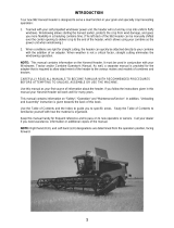
The transport option can be installed on 21 and 25 foot headers to allow towing the header behind the
windrower tractor.
This supplement provides instructions for Set-Up, Transport Safety and Converting to and from Transport
Position, recommended Maintenance and Repair Parts Listing.
TABLE OF CONTENTS
Set-up Instructions ..............................................................................................................................2 - 22
Transport Safety.......................................................................................................................................23
Converting from Field Position to Transport .....................................................................................24 - 29
Converting from Transport to Field Position .....................................................................................30 - 34
Maintenance / Service........................................................................................................................35, 36
Repair Parts ......................................................................................................................................37 - 53

SET-UP INSTRUCTIONS
Form # 131126 Issue 11/07
2
LEFT END (FORWARD) WHEEL
1. On bottom flange of left endsheet, drill
two 0.656” holes* (B) as shown.
NOTE: Holes in bottom flange may be
round or square.
* These holes will be present on headers
built in Model Year 2001 and later.
2. Attach left wheel assembly at the two
holes drilled in step 1, using 5/8 x 1-1/4
carriage bolts at (H) (heads down) and
5/8 flange nuts.
3. Mark the position for hole (A) on the
endsheet, using the wheel assembly as
a guide. Drill a 0.656” diameter hole*.
* This hole will be present on headers
built in Model Year 2001 and later.
4. Position brace tube so that hole (C) is
484 mm (19.05”) from left endsheet as
shown. Mark this position and tack weld
a 5/8 x 1 inch black bolt from kit to main
tube. Position brace onto bolt and
confirm proper bolt position, then
remove brace from bolt and place a 5
mm (3/16”) weld completely around bolt
head.
NOTE: Ends of brace will bend slightly when initially tightened.
26 mm = 1.02”
170 mm = 6.69”
193 mm = 7.60”
LEFT ENDSHEET HOLES
LEFT ENDSHEET HOLE & WELDED BOLT

SET-UP INSTRUCTIONS
Form # 131126 Issue 11/07
3
LEFT END (FORWARD) WHEEL (continued)
5. Remove left wheel assembly installed in
step 2.
6. Align holes in plate (C) (from kit) with
endsheet holes and place a 3mm (1/8”)
fillet weld all around the outside edges of
plate (C).
NOTE: Two bolts can be used in holes to
hold plate (C) during welding.
7. Align hole in plate (D) (from kit) with
endsheet hole and mate the radius of plate
with backtube. Place a 3mm (1/8”) fillet
weld around the outsides edges of plate
(D).
NOTE: A bolt can be used to hold plate (D)
in position during welding.
C
WELD OUTER SUPPORT PLATE – L/H ENDSHEET
WELD INNER SUPPORT PLATE – L/H ENDS SHEET
D

SET-UP INSTRUCTIONS
Form # 131126 Issue 11/07
4
LEFT END (FORWARD) WHEEL (continued)
IMPORTANT: Steps 8-11 are for single sickle headers, for double sickle headers proceed to step 12.
8. Bolt left hand caster mount (E) into position
against inside surface of plate (D) welded in step 7
(refer to page 6 for instruction).
9. Position triangular gusset (F) (from kit) 6mm (1/4”)
above left hand caster mount and flush against
plate (D) and backtube. Tack gusset (F) in
position.
10. Remove left hand caster mount and weld gusset
(F). Place a 5mm (3/16“) fillet weld on top and
bottom edges against header backtube and plate
(D).
11. Proceed to step 15.
MOUNT LEFT HAND CASTER SUPPORT
D
E
F
POSITION & WELD GUSSET (F)

SET-UP INSTRUCTIONS
Form # 131126 Issue 11/07
5
LEFT END (FORWARD) WHEEL
(continued)
IMPORTANT: Steps 12-15 are for double sickle headers, for single sickle headers see page 4.
12. Bolt left hand caster mount (E) into position
against inside surface plate (D) welded in step 7
(refer to next page for instruction).
13. Position rectangular (100 x 68mm) gusset (G)
(from kit) 6mm (1/4”) above left hand caster mount
and flush against plate (D) and backtube. Position
the 100mm (4”) side of gusset against plate (D).
Tack gusset (G) in position.
14. Remove left hand caster mount and weld gusset
(G). Place a 3mm (1/8”) fillet weld on top and
bottom edges against header backtube, end panel
gusset and plate (D).
MOUNT LEFT HAND CASTER SUPPORT
D
E
POSITION & WELD GUSSET (G)
(
END PANEL GUSSET REMOVED FOR CLARITY)
G

SET-UP INSTRUCTIONS
Form # 131126 Issue 11/07
6
LEFT END (FORWARD) WHEEL
(continued)
15. Install left wheel assembly as shown below:
• At the two holes in bottom flange of endsheet, use two 5/8 x 1-1/4 carriage bolts at (H) (heads
down) and 5/8 flange nuts.
• At hole in side of left endsheet, use one 5/8 x 2” hex head bolt (D), 5/8 flat washers (F) (three for
single sickle & four for double sickle headers), and 5/8 flange nut (G).
• At bolt welded to frame tube, use one 5/8 flange nut (J) to secure brace tube.
• Attach storage bracket to rear of left endsheet with two 1/2 x 1 inch short neck carriage bolts and
1/2 flange nuts at (K).
NOTE: For single sickle headers
, If not present, drill 0.531” hole (L) at dimensions shown. For
double sickle drive headers, at top bolt, use the existing belt tension adjusting bolt to secure
bracket.
LEFT WHEEL ASSEMBLY
Three required for Single Sickle
Four required for Double Sickle.

SET-UP INSTRUCTIONS
Form # 131126 Issue 11/07
7
RIGHT END (REAR) WHEEL
1. On bottom flange of right endsheet, drill two 0.656” holes* (C) as shown.
NOTE: Holes in bottom flange may be round or square.
* These holes will be present on headers built in Model Year 2001 and later.
38 mm = 1.50”
100 mm = 3.94”
80 mm = 3.15”
RIGHT ENDSHEET HOLES

SET-UP INSTRUCTIONS
Form # 131126 Issue 11/07
8
RIGHT END (REAR) WHEEL
(continued)
2. Attach right wheel assembly at the two holes
drilled in Step 1, using 5/8 x 1-1/4 carriage head
bolts at (K) (heads down) and 5/8 flange nuts.
Secure at gusset under frame tube with 5/8 x 1-
1/4 carriage head bolt (M) and flange nut.
3. Drill a 0.812” diameter hole in the endsheet,
using the hole (A) in wheel assembly as a
guide. (Disassemble as required for fit-up.) This
hole will be present on headers built in Model
Year 2001 and later.
4. Mark the position for hole (B) as follows:
For double sickle drive headers: Use the rear
hole in support (J) as shown.
For single sickle drive headers: Use the forward
hole in support (J).
Drill a 0.750” diameter hole. This hole will be present on headers built in Model Year 2001 and later.
5. Position brace tube so that hole (C) is 484 mm (19.05”) from right endsheet as shown. Mark this
position and tack weld a 5/8 x 1 inch black bolt from kit to main tube. Position brace onto bolt and
confirm proper bolt position, then remove brace from bolt and place a 5 mm (3/16”) weld completely
around bolt head.
RIGHT ENDSHEET HOLES – DOUBLE SICKLE
HEADER SHOWN
A
B
RIGHT ENDSHEET HOLES & WELDED BOLT

SET-UP INSTRUCTIONS
Form # 131126 Issue 11/07
9
RIGHT END (REAR) WHEEL
(continued)
6. Install right wheel assembly as shown below:
• Install 3/4 x 4-1/2” hex head bolt through wheel assembly and new 0.812” hole in endsheet.
Position plate (G) on outside face of endsheet and secure with 3/4 nut (E).
NOTE: If necessary, elongate hole in endsheet horizontally as required to fit.
• At new 0.75” hole in endsheet, install 5/8 x 1-1/4 hex head bolt (F) and secure with nut (H).
NOTE: For double sickle drive headers
use top hole in plate (G) and rear hole in support (J) as
shown. For single sickle drive headers
, use lower hole in plate (G) and forward hole in support (J).
• At bolt welded to frame tube, use one 5/8 flange nut (L) to secure brace tube.
RIGHT WHEEL ASSEMBLY

SET-UP INSTRUCTIONS
Form # 131126 Issue 11/07
10
FRONT (CUTTERBAR) WHEEL
1. At right hand header leg
, remove skid shoe, if installed.
2. Weld rectangular bar (A) across bottom of leg, using a 5 mm (3/16”) weld on top surface (B) both
sides as shown below. Ensure there is no weld at edges.
3. Weld two cropped bars* (C) to sides of leg, with crop towards cutterbar as shown below. Use a 5 mm
(3/16”) weld at edges (D), both sides.
* These welded bars (C) will be present on headers built in Model Year 2001 and later.
10 mm = 0.39”
227 mm = 8.94”
259 mm = 10.20”
R/H LEG MODIFICATIONS

SET-UP INSTRUCTIONS
Form # 131126 Issue 11/07
11
FRONT (CUTTERBAR) WHEEL
(continued)
4. Install front wheel assembly as shown below.
• Install wheel assembly over guard tips (E) at right header leg.
• Ensure clamp is seated up inside leg.
• Operate lever (F) to engage clamp on leg plate.
• If leg mounted skid shoes are required, install new shoe (G) (with higher front lip) from kit at right
header leg.
NOTE: Leg mounted skid shoes can not be installed when combine adapter is installed.
FRONT WHEEL ASSEMBLY

SET-UP INSTRUCTIONS
Form # 131126 Issue 11/07
12
580 mm = 22.84”
280 mm = 11.02”
ATTACH HITCH TO TRACTOR
HITCH
1. Slide bracket (A) over walking beam and
position as shown below. Secure with two 5/8 x
5-1/2” hex head bolts and flange nuts.
2. Route hitch chain (B) through chain support on
bracket (A), then wrap around walking beam
and lock hook on chain.
3. Position storage bracket (C) as shown below
and secure with U-bolt and 1/2 NC flange nuts.
4. Remove SMV sign from welded mount. Attach
extension bar (D) to welded mount using new
self-tapping screws.
NOTE: Use the larger holes in bar (D) to attach
to welded mount. It may be necessary to bend
the welded mount out slightly.
5. Attach SMV sign to smaller holes in bar (D)
using the existing self-tapping bolts removed
form welded mount.
6. Remove split ring and remove lock pin from
hitch knee joint at (E).
7. Store hitch as follows: Place front section of
hitch on top of storage bracket (C) at right side
of walking beam. Fold hitch and place rear
section into notch in bottom of bracket (C).
Install pin from knee joint to lock the two
sections at (G) and secure with split ring.
E
REMOVE LOCK PIN FROM HITCH JOINT
C
G
HITCH STORAGE

SET-UP INSTRUCTIONS
Form # 131126 Issue 11/07
13
TRANSPORT LIGHTS ON HEADER
1. Open left hand drive shield and route header section of transport wiring harness through inside of
frame tube to right endsheet.
NOTE: The end of the harness with the 6-way connector goes to the right endsheet.
NOTE: For European applications, the lamp module
referred to in steps 2 and 3 is not used. Header
harness connects directly to end sheet harness.
2. At the R/H end sheet, install lamp module and
support as follows: For Single Sickle Headers
,
Install at (N) with the hardware that secures the
sickle storage tube as shown at right. For Double
Sickle Headers, install at clamp (V) as shown
below.
3. Connect header harness and end sheet
harness to lamp module. Route end sheet
harness to top of end sheet through hole at reel
support arm anchor (S).
4. Install lights at R/H endsheet as shown at right,
using the hardware that secures the pivoting
amber lights. Secure harness with plastic tie at
(R). NOTE: For European applications, pivoting
amber lights are not installed. Install transport
lights using hardware provided.
NOTE: Wire colors do not match up when
connecting harness to lights. Refer to wiring
schematic on Page 15.
INSTALL LAMP MODULE – Double Sickle
(EXCEPT EUROPEAN APPLICATIONS)
V
R
S
INSTALL LIGHTS AT END SHEET
INSTALL LIGHTS AT ENDSHEET
S
R
N
INSTALL LAMP MODULE
–
Single Sickle
(EXCEPT EUROPEAN APPLICATIONS)

SET-UP INSTRUCTIONS
Form # 131126 Issue 11/07
14
TRANSPORT LIGHTS ON HEADER
(continued)
5. Install lights at R/H reel support arm using ½ x
1 inch carriage bolts and flange nuts as shown.
Mounting for 2001 and newer headers shown
in top photo. For pre-2001 headers, light mount
is attached as shown in second photo.
NOTE: For headers with floating divider option, a
different light mounting bracket is required. See
instructions packaged with dividers.
6. For 2001 and newer headers, install harness
guard as shown at (A). For pre-2001 header
install harness guard as shown at (B).
7. Install harness guard holder (G) on reel arm as
shown. Secure holder with 5/8 x 1 inch hex
head bolt and lock nut. Route harness up
inside reel support arm and over bolt (D). Pass
harness through guard to lights and make the
connections. Secure harness with plastic tie at
(C) (see inset, top photo).
NOTE: Wire colors do not match up when
connecting harness to lights. Refer to wiring
schematic on page 15.
8. For single sickle drive headers
, attach Slow Moving Vehicle sign with spacer, 3/8 x 1 ¾ carriage bolt
and flange nut as shown below left.
For double sickle drive headers
, drill a 0.406” hole in SMV sign, centered on base and 2.16” (55 mm)
from bottom of sign as shown at (E). Also drill a 0.406” hole in RH reel arm located 7 ½” (190 mm)
rearward of reel lift cylinder pin (F), and 3/8” (10 mm) above centerline of reel lift cylinder pin (F).
Attach sign with spacer, 3/8 x 1 ¾ carriage bolt and flange nut as shown below right.
G
D
INSTALL GUARD HOLDER
INSTALL SMV SIGN
(DOUBLE SICKLE DRIVE HEADERS)
E
F
INSTALL SMV SIGN
(
SINGLE SICKLE DRIVE HEADERS
)
A
INSTALL LIGHTS & HARNESS GUARD AT
R/H REEL ARM
C
B
INSTALL LIGHTS & HARNESS GUARD AT
R/H REEL ARM - Pre-2001 Header

SET-UP INSTRUCTIONS
Form # 131126 Issue 11/07
15
TRANSPORT LIGHTS ON HEADER
(continued)
9. At left end, route harness (G) as shown and
engage tab of 4-way connector in hole in
endsheet at (H) for storage. Ensure harness
will reach to hitch section before securing.
10. Secure harness at clamp (J) and cable tie at
(K) as shown. Attach harness ground wire at
bolt for clamp (J) with 3/8 nut provided.
CONNECTIONS TO LIGHTS
HEADER HARNESS – LEFT END
DOUBLE SICKLE
G
H
K
J
HEADER HARNESS – LEFT END
SINGLE SICKLE
H
G
K

SET-UP INSTRUCTIONS
Form # 131126 Issue 11/07
16
REFLECTORS ON HEADER
1. Add eight amber reflectors to header as shown below:
FRAME TUBE AT CENTER OPENING
LEFT END – TWO REFLECTORS
WRAP THREE REFLECTORS
A
R
OU
ND
C
ENTER
O
F REEL T
U
BE
RIGHT END – TWO REFLECTORS
SINGLE SICKLE HEADER
RIGHT END – TWO REFLECTORS
DOUBLE SICKLE HEADER

SET-UP INSTRUCTIONS
Form # 131126 Issue 11/07
17
RE-ROUTE HEADER HOSES AND HARNESS
1. At left header leg, remove reel lift hose and
header wiring harness from their clamped
position at (A). Remove female 1/4” quick
coupler from reel lift hose.
2. Re-route reel lift hose and header wiring
harness into v-channel under main tube and out
rectangular hole at (B). Reinstall quick coupler
on reel lift hose.
3. Remove clamp from draper drive hoses at (B).
4. Install new support (C) as shown, using existing
hardware. Remove female quick coupler from
draper drive hose and install on support (C)
with dished washer (D) positioned as shown
below. Install insulated clip (E) with 3/8 x 3/4”
carriage bolt and flange nut to attach reel lift
hose and header wiring harness.
5. Connect harness extension (F) from kit [1200
mm, (48”) long] to header harness and tie to
draper drive hose and reel lift hose as shown.
HOSE / HARNESS ROUTING
A
B
F
HOSE / HARNESS ROUTING
C
F
HOSE / HARNESS ROUTING
E
D

SET-UP INSTRUCTIONS
Form # 131126 Issue 11/07
18
RE-ROUTE HEADER HOSES AND HARNESS
(continued)
6. At right header leg, remove reel drive hoses
from the existing mounting bracket. Remove
bracket from header.
7. Install hoses on new support (G) and mount
support to header leg as shown with two 3/8 x
3/4 carriage bolts and flange nuts (nuts inside
leg).
REEL DRIVE HOSE MOUNT
REEL DRIVE HOSE MOUNT
G
/