Page is loading ...

For service or repairs to boiler, call your heating contractor. When seeking information on boiler,
provide Boiler Model Number and Serial Number as shown on Rating Label.
Boiler Model Number
FORCESTEAM0 _
Boiler Serial Number Installation Date
Heating Contractor Phone Number
Address
106324-04 - 4/18 Price - $5.00
INSTALLATION, OPERATING
AND
SERVICE INSTRUCTIONS
FORCESTM™ SERIES
GAS BOILER
9700609

2
106324-04 - 4/18
FOLLOW ALL INSTRUCTIONS and warnings
printed in this manual and posted on the boiler.
INSPECT THE BOILER ANNUALLY. To keep
your boiler safe and efficient, have a service
technician follow the Service checklist near the
end of this manual.
IF YOU ARE NOT QUALIFIED to install or service
boilers, do not install or service this one.
THE BOILER MAY LEAK WATER at the end of its
useful life. Be sure to protect walls, carpets, and
valuables from water that could leak from the
boiler.
PROTECT YOUR HOME IN FREEZING
WEATHER. A power outage, safety lockout, or
component failure will prevent your boiler from
lighting. In winter, your pipes may freeze and
cause extensive property damage. Do not leave
the heating system unattended during cold
weather unless alarms or other safeguards are in
place to prevent such damage
DO NOT BLOCK AIR FLOW into or around the
boiler. Insufficient air may cause the boiler to
produce carbon monoxide or start a fire.
KEEP FLAMMABLE LIQUIDS AWAY from the
boiler, including paint, solvents, and gasoline.
The boiler may ignite the vapors from the liquids
causing explosion or fire.
KEEP CHILDREN AND PETS away from hot
surfaces of the boiler, boiler piping, and vent
pipe.
CARBON MONOXIDE (CO) is an odorless,
deadly gas that may be introduced into your
home by any malfunctioning fuel-burning product
or vent system failure. Consider installing CO
alarms near bedrooms in all levels of the building
to warn you and your family of potential CO
exposure.
WARNINGS FOR THE HOMEOWNER

3
3
106324-04 - 4/18
READ THIS ENTIRE MANUAL before attempting
installation, start-up, or service. Improper
installation, adjustment, alteration, service,
or maintenance may cause serious property
damage, personal injury, or death.
DO NOT DISCONNECT PIPE FITTINGS on
the boiler or in the heating system without first
verifying that the system is cool and free of
pressure and that your clothing will protect you
from a release of hot water or steam. Do not rely
solely on the boiler’s temperature and pressure
gage when making this judgment.
USE PROPER PERSONAL PROTECTION
EQUIPMENT when servicing or working near the
boiler. Materials of construction, flue products,
and fuel contain alumina, silica, heavy metals,
carbon monoxide, nitrogen oxides, and/or
other toxic or harmful substances that can are
hazardous to health and life and that are known
to the State of California to cause cancer, birth
defects, and other reproductive harm.
INSTALL ALL GUARDS, cover plates, and
enclosures before operating the boiler.
SIZE THE BOILER PROPERLY relative to the
design heat load or, if using domestic hot water
priority, the peak hot water load, whichever
is larger. A grossly oversized boiler will cycle
excessively and this will lead to premature failure
of the boiler and its components. Our warranty
does not apply to damage from excessive
cycling.
ADHERE TO ALL LOCAL CODE
REQUIREMENTS. Contact your local code
inspector prior to installation. In the absence of a
local code, adhere to the National Fuel Gas Code
ANSI Z223.1/NFPA 54.
ALL WIRING must comply with the National
Electrical Code ANSI/NFPA 70.
WARNINGS FOR THE INSTALLER

4
106324-04 - 4/18
TheFORCESTMseriesboilersarelowpressurecastirongasredsteamboilersdesignedforuseinclosedsteam
heatingsystems.TheseboilersareCategoryIdraftdiverterequippedappliances,whichmustbeventedbynaturaldraftusing
alinedmasonryorlistedmetalchimneysystem.Anadequatesupplyofairforcombustion,ventilationanddilutionofue
gasesmustbeavailableintheboilerroom.Theseboilersarenotdesignedforuseinprocessorother“open”steamsystems
TABLE OF CONTENTS
I. Product Description.................................................................................... 4
II. Specications............................................................................................ 5
III. Pre-Installation........................................................................................... 6
IV. Locating the Boiler..................................................................................... 6
V. Air for Combustion & Ventilation................................................................ 7
VI. Venting....................................................................................................... 8
VII. Gas Piping................................................................................................. 10
VIII. System Piping............................................................................................ 11
IX. Indirect Water Heater Piping...................................................................... 14
X. Electrical.................................................................................................... 15
XI. System Start-Up........................................................................................ 20
XII. Service Instructions................................................................................... 25
XIII. Troubleshooting.......................................................................................... 29
XIV. Repair Parts.............................................................................................. 33
Appendix A - Tapping Locations................................................................. 44
I. Product Description

5
5
106324-04 - 4/18
TABLE 1: FORCESTM SPECIFICATIONS
II. Specications
FIGURE 1: FORCESTM BOILERS - GENERAL CONFIGURATION
Boiler Model
Approx.
Shipping
Weight
Lbs.
Dimensions (in inches)
Recommended Min.
Round
Chimney Size
(Diameter x Height)
(1)
Gas
Conn.
(NPT)
Water Volume
(Gal.)
'A' 'B' 'C' 'D'
Steam
Boiler
(2)
FORCESTM03 350 12¾
28
40-7/16
4 4" x 15 ft.
1/2"
5.1 3.9
FORCESTM04 420 16 5 5" x 15 ft. 6.5 5.0
FORCESTM05 485 19¼
6 6" x 15 ft.
7.9 6.1
FORCESTM06 555 22½ 9.3 7.2
FORCESTM07 620 25¾
30 7 7" x 15 ft. 3/4"
10.7 8.3
FORCESTM08 690 29 12.1 9.4
(1) 15' chimney height is from bottom of Draft Hood opening to top of Chimney.
(2) Steam boiler's "steamable water volume": water volume from NWL (normal water level) to low water cutoff level.
Heating Surface: 4.35 sq. ft. per ueway (steam); 5.72 sq. ft. per ueway (water)

6
106324-04 - 4/18
1) Safe,reliableoperationofthisboilerdependsuponinstallationbyaprofessionalheatingcontractorinstrictaccordance
withthismanualandtherequirementsoftheauthorityhavingjurisdiction.
• Intheabsenceofanauthorityhavingjurisdiction,installationmustbeinaccordancewiththismanualandthe
National Fuel Gas Code,ANSIZ223.1/NFPA54.
• Whererequiredbytheauthorityhavingjurisdiction,thisinstallationmustconformtotheStandard for Controls and
Safety Devices for Automatically Fired Boilers(ANSI/ASMECSD-1).
2) Makesurethataproperlysizedchimneyisavailablewhichisingoodcondition.Consulttheauthorityhaving
jurisdiction,PartVIofthismanual,andtheNational Fuel Gas Codeforadditionalinformationonventingrequirements.
3) Makesurethattheboileriscorrectlysized.UseanindustryacceptedsizingmethodsuchastheI=B=R Installation
Guide for Residential Hydronic Heating Systems (Pub. #200) and I=B=R Heat Loss Calculation Guide(Pub.#H21or
#H22).
4) Makesurethattheboilerreceivedisconguredfornaturalgas.
5) GasConversionKitsarelistedbelow:
FORCESTM03 FORCESTM04 FORCESTM05 FORCESTM06 FORCESTM07 FORCESTM09
Natural to LP
(Propane)
106567-01 106567-02 106567-02 106567-03 106567-04 106567-04
LP (Propane) to
Natural
106568-01 106568-02 106568-02 106568-03 106568-04 106568-04
Warning
This Product Must be Installed By A Licensed Plumber Or Gas Fitter
when Installed Within The Commonwealth Of Massachusetts
IV. Locating the Boiler
1) Clearances:
• Observetheminimumclearancesshownbelow.Theseclearancesapplytoallcombustibleconstruction,aswellas
noncombustiblewalls,ceilingsanddoors.AlsoseeFigure2.
Front–18”
RightSide–18”
LeftSide–6”
Rear–6”
Top–17”
• A24”serviceclearancefromthejacketisrecommendedontheleft,right,andfrontoftheboiler.Theseclearances
maybereducedtothoseshowninFigure2,howeverservicingtheboilerwillbecomeincreasinglydifcultasthese
serviceclearancesarereduced.
• Iftherightside24”serviceclearanceisreduced,adequateclearancemustbemaintainedtoeasilyreadandaccessthe
controls.Alternatively,accessmaybeprovidedusingadoor
2) Thisboilermaybeinstalleddirectlyoveranon-carpetedcombustibleoor.
I. Pre-Installation

7
7
106324-04 - 4/18
3) Theboilermustbeinstalledonahardlevelsurface.
4) Donotinstallthisboilerinalocationwheregasolineorotherammablevaporsorliquidswillbestoredorused.Donot
installthisboilerinanareawherelargeamountsofairbornedustwillbepresent,suchasaworkshop.
5) Theboilershouldbelocatedasclosetothechimneyaspossible.
6) Donotinstallthisboilerdirectlyonasurfacethatmaygetwet.Raisetheboileronapad.
FIGURE 2: FORCESTM BOILERS - CLEARANCES TO ALL TYPES OF COMBUSTIBLE CONSTRUCTION
AND NONCOMBUSTIBLE CEILINGS, WALLS, AND DOORS.
V. Air for Combustion & Ventilation
IV. Locating the Boiler
(continued)
Sufcientfreshairmustbesuppliedforcombustion,ventilationanduegasdilution.Provisionsforcombustion,ventilationand
uegasdilutionairforgasutilizationequipmentventedbynaturaldraftmustbemadeinaccordancewithlocalbuildingcodesor,
inabsenceofsuchcodes,inaccordancewith“AirforCombustionandVentilation”oftheNational Fuel Gas Code,ANSIZ223.1/
NFPA54.

8
106324-04 - 4/18
VI. Venting
Ventinstallationmustbeinaccordancewithlocalbuildingcodes,orthelocalauthorityhavingjurisdiction,ortheNational Fuel
Gas Code,ANSIZ223.1/NFPA54.
1. AtypicalventinstallationisillustratedbyFigure3.Thecomponentsofventinstallationaretheventdamper(ifused),
ventconnectorandchimney.
2. Installventdamper(seeFigure4)asfollows:
a) Openventdampercartonandremoveinstallationinstructions.Readtheinstructionsthoroughlybeforeproceeding.
Verifythatventdamperissamesizeasdraftdiverteroutlet.SeeFigure1.Unpackventdampercarefully.Do not
force closed damper blade. Forcingventdamperclosedmayresultindamagedgeartrainandvoidwarranty.
b) Ventdamperisfactoryshippedhavingapproximately¾”diameterholeintheventdamperblade,whichmust be left
openforboilersequippedwithstandingpilot,andshouldbepluggedonboilerswithanintermittentpilotsystem,
usingtheplugsuppliedwiththedamper.
Mounttheventdamperontheuecollarwithoutmodicationtoeitherandsecurewithsheetmetalscrews.Make
surescrewsdonotinterferewithdamperbladeoperation.Ventdamperbladepositionindicatormustbevisibleto
users.
c) Thedamperwireharnessisshippedwiredintotheboilerjunctionbox.Plugthelooseendofthisharnessintothe
damperandsecuretheexibleconduittothedamperusingaconnectornutprovided.
d) Installventconnectorpipeandventttingsfromventdamperoutlettochimneyorgasvent.Securewithsheetmetal
screwsandsupportasrequired.
3. GasVentTermination
Gasventslocatednotlessthan8ft.(24m)fromaverticalwallorsimilarobstructionshallterminateabovetheroofin
accordancewithFigure5andTable2.
FIGURE 3: FORCESTM BOILER TYPICAL VENT SYSTEM INSTALLATION AND COMPONENTS

9
9
106324-04 - 4/18
FIGURE 4: VENT DAMPER INSTALLATION DETAILS
VI. Venting (continued)
Listed
cap
Listed
gas vent
H (minimum) -
Minimum height from roof
to lowest discharge opening
Roof pitch is x/12
12
x
Lowest discharge opening
FIGURE 5: TERMINATION LOCATIONS FOR GAS VENTS
WITH LISTED CAPS AT LEAST 8 FT (2.4 M)
FROM A VERTICAL WALL:
Roof Slope H (minimum)
ft m
Flat to 6/12 1.0 0.30
Over 6/12 to 7/12 1.25 0.38
Over 7/12 to 8/12 1.5 0.46
Over 8/12 to 9/12 2.0 0.61
Over 9/12 to 10/12 2.5 0.76
Over 10/12 to 11/12 3.25 0.99
Over 11/12 to 12/12 4.0 1.22
Over 12/12 to 14/12 5.0 1.52
Over 14/12 to 16/12 6.0 1.83
Over 16/12 to 18/12 7.0 2.13
Over 18/12 to 20/12 7.5 2.27
Over 20/12 to 21/12 8.0 2.44
TABLE 2: ROOF SLOPE HEIGHTS

10
106324-04 - 4/18
FIGURE 6: GAS CONNECTION TO BOILER
VII. Gas Piping
*
*StateofMassachusettsRequiresManual
Shut-offValvetobe“T”HandleType
Gaspipingtotheboilermustbesizedtodeliveradequategasfortheboilertoreatthenameplateinputatalinepressure
betweentheminimumandmaximumvaluesshownontheratingplate.Formoreinformationongaslinesizing,consultthe
utilityorChapter2oftheNational Fuel Gas Code.
Figure6showstypicalgaspipingconnectiontotheFORCESTMboiler.Asedimenttrapmustbeinstalledupstreamof
allgascontrols.Installamanualshut-offvalveoutsidethejacketandgroundjointunionasshown.
Theboileranditsgasconnectionmustbeleaktestedbeforeplacingtheboilerinoperation.Whendoingthis,theboiler
anditsindividualshut-offmustbedisconnectedfromtherestofthesystemduringanypressuretestingofthatsystemat
pressuresinexcessof1/2psi.Whenpressuretestingthegassystematpressuresof1/2psiorless,isolatetheboilerfromthe
gassupplysystembyclosingitsindividualmanualshut-offvalve.

11
11
106324-04 - 4/18
CAUTION
• INSTALLBOILERSOTHATTHEGASIGNITIONSYSTEMCOMPONENTSAREPROTECTED
FROMWATER(DRIPPING,SPRAYING,RAIN,ETC.)DURINGAPPLIANCEOPERATIONANDSERVICE
(CIRCULATORREPLACEMENT,ETC.).
• OPERATIONOFTHISBOILERINASYSTEMHAVINGSIGNIFICANTAMOUNTSOFDISSOLVED
OXYGENCANCAUSESEVEREHEATEXCHANGERCORROSIONDAMAGE.
VIII. System Piping
General Piping Notes
Figure7showsrecommendednearboilerpipingformostcommontypesofgravityreturnsteamsystems.Additional
informationonsteamsystemdesignmaybefoundinInstallation Guide for Residential Hydronic Heating Systems(Pub.
#200).
Oneoftheprimarypurposesofthisnearboilerpipingistoseparatetinywaterdropletsfromthesteamexitingtheboiler
sothat“dry”steamissenttothesystem.Ifthenearboilerpipingisnotcorrect,wetsteamwillenterthesystemandthe
followingproblemsmayoccur:
• Short cycling on low water
• BoilerorsystemFlooding
• Hammering
• Failuretoheatoneormoreradiators
AvoidthethreecommonpipingmistakesshowninFigure8.Thisapplieseveniftheexistingboilerhasoneofthepiping
mistakesshowninFigure8andappearstobeworking.Iftwoormoresteammainsmustbeconnectedtotheboiler,connecta
separatetake-offforeachmainintotheheaderbetweentheriser(s)andequalizer.Alsonotethefollowingpoints:
1) Asizereductionmustbemadetoconnecttheheadertotheequalizer.Thisreductionmustbemadeintheequalizerline.
Donotmakethissizereductioninthehorizontalheader.
2) Onepipesteamsystemsrequireairventsoneachradiator,aswellasattheendofeachmain.Forthesystemtowork
properly,theseventsmustbeproperlyinstalled,sized,andbeingoodcondition.Inspectandreplaceanydefectivevents.
Iftherearenoventsattheendsofthemains,installthem.
3) DonotattempttomanifoldmultipleFORCESTMboilerswithgravityreturns.
4) Forinstallationswithcondensateorboilerfeedpumps,followthepumpmanufacturer’spipinginstructions.Such
systemsgenerallydonotrequireHartfordloops.
5) Donotuseacheckvalveinplaceof,orinadditionto,aHartfordlooponagravityreturnsystem.
6) Pipethellconnectionfromacleansourceofcoldwater.Whenthewatersupplyisfromawell,makesurethatastrainer
isinstalledinthewellsystem.
7) PipingwithaChiller-Iftheboilerisusedinconjunctionwithachiller,pipetheboilerinparallelwithchiller.Use
isolationvalvestopreventchilledwaterfromenteringtheboiler.

12
106324-04 - 4/18
Piping Installation
1) Removepartsbagfromboilercrate.
2) Installsafetyvalve(spindlemustbeinverticalposition)intotappingonboilerleftside(seeFigure1)usingthe3/4”NPT
nippleandelbowsupplied.
3) Pipethedischargeofthesafetyreliefvalvetoalocationwherewaterorsteamwillnotcreateahazardorcauseproperty
damageifthevalveopens.Theendofthedischargepipemustterminateinanunthreadedpipe.Ifthesafetyvalve
dischargeisnotpipedtoadrainitmustterminateatleast6inchesabovetheoor.Theterminationofthesafetyvalve
dischargepipingmustbeinanareawhereitisnotlikelytobecomepluggedbydebrisorsubjectedtofreezing.
4) Installdrainvalveintotappingonboilerleftsideusingthe2x3/4bushingprovided(seeFigure1).
5) Connectsystemsupplyandreturntoboiler.SeeFigure7.FORCESTM03throughFORCESTM06maybepipedwith
oneortworisers.Install2”pluginTappingGifoptionalsecondsupplyAisnotused.Twosupplyrisersarerequiredon
theFORCESTM07andFORCESTM08.
6) PipingwithaChiller-Iftheboilerisusedinconjunctionwithachiller,pipetheboilerinparallelwithchiller.Use
isolationvalvestopreventchilledwaterfromenteringtheboiler.
DANGER
•
PIPESAFETYVALVEDISCHARGETOASAFELOCATION.
• DONOTINSTALLAVALVEINTHESAFETYVALVEDISCHARGELINE.
• DONOTMOVESAFETYVALVEFROMFACTORYLOCATION.
• DONOTPLUGSAFETYVALVEDISCHARGE.
• DONOTINSTALLASAFETYVALVEWITHASETTINGGREATERTHAN15PSI.
VIII. System Piping (continued)

13
13
106324-04 - 4/18
FORCESTM03 /
FORCESTM04 /
FORCESTM05 /
FORCESTM06
FORCESTM07 /
FORCESTM08
A
2** 2
B
2 3
C
1½ 1½
D
1¼ ¼
** Optional
FIGURE 8: COMMON NEAR-BOILER PIPING MISTAKES
FIGURE 7: STEAM BOILER PIPING FOR GRAVITY RETURN
MINIMUM PIPE SIZE
VIII. System Piping (continued)

14
106324-04 - 4/18
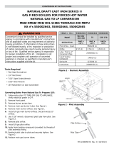
AllFORCESTMseriesboilersareequippedwithtappingstopermittheconnectionofaLinkSL™IndirectWater
Heater,orotherindirectwaterheater.Inthistypeofsystem,hotboilerwaterisdrawnfrombelowthewaterlineand
passedthroughtheheatexchangerintheindirectwaterheater.Thissectiondescribesboiler-sidepipingonly.RefertoLink
SL™Installation,OperatingandServiceInstructionsforadditionalinformation
.Thecomponentsinthissystemandtheir
functionsareasfollows:
1) Circulator-MountthecirculatorasshowninFigure9.Thecirculatorshouldbelocatedaslowandasclosetothe
boileraspractical.Donotinstallvalves,orotherdeviceshavingasignicantpressuredrop,betweentheboiler
andthecirculatorinlet.Allpipingbetweentheboilerandthecirculatorinletshouldbe1”,regardlessofthesizeof
thepipingrequiredintherestofthesystem.SeeFigure10inPartXforwiringinformation.
2) “Y”Strainer-Installa“Y”strainertopreventsedimentfromaccumulatinginsidetheindirectwaterheater.
3) CheckValve-Preventsgravitycirculationthroughtheindirectwaterheaterwhentheboilerisrespondingtoacall
forheat.
4) BoilerLimitControl-UseaSPSTbreak-on-risetemperaturelimitcontrolsuchastheHoneywellL4006A.Donot
setthelimitabove180°Fasdoingsomaycausetheboilertosteamwhenthereisnocallforheat.SeeFigure10
forwiringinformation.
5) ValvesandUnions-Installshut-offvalves,drainvalves,andunionsinlocationsthatwillfacilitatemaintenanceof
thesystem.Donotinstallanyvalvesbetweentheboilerandcirculatorinlet.
IMPORTANT
• Someindirectwaterheatersmaynotbesuitableforusewithasteamboiler.Consultthewaterheater
manufacturer’sguidelinesbeforeinstallingitinthistypeofsystem.
• Boilerwatertemperaturesandowratesinthistypeofsystemmaybeconsiderablylowerthanthoseupon
whichthewaterheatermanufacturer’sratingsarebased.Thismayresultinsubstantiallylongerwaterheater
recoverytimes.
FIGURE 9: INDIRECT WATER HEATER BOILER-SIDE PIPING
IX. Indirect Water Heater Piping

15
15
106324-04 - 4/18
1) 120VoltWiring-Theboilershouldbeprovidedwithitsown15Abranchcircuitwithfuseddisconnect.All120volt
connectionsaremadeinsidethejunctionboxontheleftsideoftheboiler.Removethetransformertogainaccesstothis
box(alsoseeFigures11and12):
• Hot(“black”)-Wirenuttoblacktransformerlead
• Neutral(“white”)-Wirenuttowhitetransformerlead
• Ground(“green”orbare)-Groundscrewinsidejunctionbox.
2)ThermostatWiring-Followthermostatmanufacturerinstructions.Toinsureproperthermostatoperation,avoid
installationinareasofpooraircirculation,hotspots(nearanyheatsourceorindirectsunlight),coldspots(outside
walls,wallsadjacenttounheatedareas,locationssubjecttodrafts).ProvideClassIIcircuitbetweenthermostatand
boiler.Connectthermostatwireleadstothebluetransformerleadandbrownrelayleadinsidethejunctionbox.Setthe
heatanticipatorto0.2A.
WARNING
Allwiringandgroundingmustbedoneinaccordancewiththeauthorityhavingjurisdictionor,intheabsenceofsuch
requirements,withtheNationalElectricalCode(ANSI/NFPA70)
X. Electrical

16
106324-04 - 4/18
FIGURE 10: WIRING INDIRECT WATER HEATER TO BOILER
Indirect Water Heater Wiring
Figure10showseldwiringforanindirectwaterheater.AHoneywellR845AorequivalentDPSTrelayandtransformer
isrequired.ThehighlimitdescribedinPartIXmustalsobesuppliedbytheinstaller.Acallforheatfromtheindirectwater
heaterthermostatwillenergizetherelaymakingbothsetsofcontacts.Onesetofthesecontactsthenenergizesthecirculator.
Theothersetofcontactswillmakethe“T”and“T”contactsontheburnerprimarycontrol,ringtheburner.Iftheboiler
watertemperatureexceedsthehighlimitsettingof180°F,thehighlimitwillopenthe“T”-“T”circuitandtheburnerwill
shutdown.
Ifthereisacallforspaceheat,theheatingthermostatwillmakethe“T”-“T”circuitandtheboilerwillrewithoutregard
tothestatusoftheindirectwaterheater.Thelowwatercut-offandpressurelimitcontrolwillinterrupt120voltpowertothe
burnerintheeventofalowwaterorexcessivepressurecondition.
X. Electrical (continued)

17
17
106324-04 - 4/18
FORCESTM Control System – Sequence of Operation
(RefertoFigures11&12forladderandconnectiondiagrams)
Sequence of Operation, Intermittent Ignition
1)Whentheboilerisenergized,24voltsisimmediatelyappliedtoterminals“1”(blue)and“4”(yellow)onthevent
damper.Assumingthatthereisnocallforheat,andthatthedamperswitchisinthe“automatic”position,thedamper
willclose.OnboilersequippedwithHydrolevelCG400Aprobetypelowwatercut-offs,voltageisalsoalwaysapplied
toterminals“1”(blue)and“2”(yellow)onthelowwatercut-offtopowerthewaterlevelsensingcircuit.
2)Assumingthatwaterisabovethecut-offlevel,powerwillappearatterminal“3”ontheCG400ALWCO.
3)Assumingthatsteampressureisbelowthepressurelimitsetting,powerwillappearononesideofrelaycontact1R1
(Graylead).Relay1RistheR8225mountedunderthejunctionbox.
4) Acallforheatfromthethermostatenergizesrelaycoil1Rcausingcontacts1R1tomake.Currentthenowsthrough
contacts1R1topinterminal“2”(orange)attheventdamperandthedamperopens.
5) Oncetheventdamperisfullyopen,anendswitchinsidethedamperwillmake,energizingpin“3”(red)atthedamper.
6) Currentpassesfromterminal“3”ontheventdamperthoughtheamerolloutandblockedvent(“spill”)switches.Under
normalconditions,bothoftheseswitchesaremadeandvoltagewillthereforeimmediatelyappearacrossterminals
“24V”and“24V(GND)”ontheignitionmodule.
7) Uponapplicationofvoltageacrossthe“24V”and“24V(GND)”terminals,theignitionmodulewillstartanignition
sparkatthepilotandapply24voltsacrossthepilotvalve(terminals“PV”and“MV/PV”).
8) Oncethepilotisestablished,thepilotamewillactasadiode,convertingtheACcurrentattheelectrodetoahalfwave
DCcurrentatthepilot’sgroundstrap.ThisDCcurrentowsthroughtheboilertothe“GND(BURNER)”connectionon
theignitionmodule.Fortheignitionmoduletorecognizethatapilotameispresent,theDCcurrentowingintothis
terminalmustbeinexcessofapproximately1.0uA.
9) Oncetheignitionmoduledetectsthepresenceofapilotame,voltageisappliedacrossthemainvalve(terminals“MV”
and“MV/PV”),openingthevalveandestablishingmainame.
10) Formoreinformationonmoduleoperation,consulttheignitionmoduleinstructionssuppliedwiththeboilerorthelocal
Fergusonrepresentative.
Safety Control Operation - Intermittent Ignition
HydrolevelCG400ALowWaterCut-off-Interruptsburneroperationifthewaterintheboilerdropsbelowasafelevel.Asthe
waterdropspastthecut-offpoint,theamberlampontheCG400Awillglow.TheCG400Awillinterruptpowertotheburners
15secondsafterthewaterleveldropspastthecut-offpoint.Thisfeaturepreventsshortcyclingoftheburnersduetoabouncing
waterline.Theburnerswillthenremainoffuntil30secondsafterthewaterlevelhasbeenraisedabovethecut-offpoint.
TheCG400Aisalsoequippedwithafeaturewhichwillshutdowntheburnersaftertheyhavebeenringfor10minutes,
regardlessofthewaterlevelstatus.TheCG400Athenkeepstheburnersofffor90seconds,allowingthewaterlevelandanyfoam
whichispresenttosettle.Duringthis90secondinterval,thegreenLEDontheCG400Awillglow.Ifthewaterlevelisstillabove
thecut-offlineattheendofthis90secondinterval,theCG400Awillrestarttheburners.
Theventdamperwillclosewhenthelowwatercut-offinterruptsburneroperation.
PressureLimitControl-Interruptsburneroperationwhenthepressureintheboilerexceedsthe“Cut-in”settingplusthe
differentialsetting.The“Cut-in”settingisshownontheoutsideofthecontrolandisadjustedusingthescrewonthetopofthe
control.Thedifferentialisadjustedusingthewhitethumbwheelontheinsideofthecontrol.Burneroperationisrestoredwhen
thepressureintheboilerdropstothe“Cut-in”pressure.
Theventdamperwillclosewhenthepressurelimitcontrolinterruptsburneroperation.
BlockedVentSwitch(BVS)-Automaticallyinterruptsburneroperationintheeventthatuegasspillsfromthedraftdiverter
opening.Thisswitchisequippedwitharesetbuttonwhichmustbepressedtorestorenormalburneroperation.Anopenblocked
ventswitchisindicativeofaproblemwiththeventsystem.Iftheblockedventswitchopens,thecauseoftheventingproblem
mustbefoundandcorrectedbyaqualiedgasservicetechnicianbeforetheblockedventswitchisreset.
FlameRolloutSwitch(FRS)-Automaticallyinterruptsburneroperationwhenamesorexcessiveheatarepresentinvestibule.
Theamerolloutswitchisasingleusedevicewhichmustbereplacedbyanidenticalswitchinordertorestorenormaloperation.
Anopenamerolloutswitchisusuallyindicativeofapluggedheatexchanger.Thecauseoftheamerolloutmustbefound
andcorrectedbyaqualiedgasservicetechnician,andtheswitchreplacedwithanidenticalone,beforetheboilerisreturnedto
operation.
X. Electrical (continued)

18
106324-04 - 4/18
FIGURE 11: WIRING DIAGRAM, HYDROLEVEL CG400A LOW WATER CUTOFF
X. Electrical (continued)

19
19
106324-04 - 4/18
FIGURE 12: LADDER DIAGRAM, HYDROLEVEL CG400A LOW WATER CUTOFF
X. Electrical (continued)

20
106324-04 - 4/18
Usethefollowingprocedureforinitialstart-upoftheboiler:
1) Makesurethattheboilerislledwithwatertothenormalwaterline(283/4inchesabovetheoororpadonwhichthe
boilerisinstalled)
2) Checkallnewgaspipingforleaksandpurgepipingsectionsthatarelledwithair.SeePart4oftheNational Fuel Gas
Codeforadditionalinformationontestingandpurginggaslines.
3) Verifythatventsystemiscompleteandfreeofobstructionsbeforeattemptingtoreboiler.
4) Inspectallwiringforlooseoruninsulatedconnections.
5) Makesurethemainburnersareseatedproperlyintherearofburnertrayandonorices.
6) Adjuststeampressurelimitcontrolforacut-inpressureof0.5psiandadifferentialpressureof1psi.
7) Adjustthermostattothehighestsetting.
8) StarttheboilerusingtheOperatingInstructions.SeeFigure14.
9) Uponinitialstart-up,thegastrainwillbelledwithair.Evenifthegaslinehasbeencompletelypurgedofair,it
maytakeseveraltriesforignitionbeforeaameisestablished.Onceaamehasbeenestablishedforthersttime,
subsequentcallsforburneroperationshouldresultinaameonthersttry.
10) Observepilotburnerame.Pilotburnerproducesthreeames.Thecenteroneshouldbeasteadymediumblueame
coveringaround3/8”to½”ofsparkelectrode/amerod.SeeFigure13.
12) Makesureventdamperisinopenpositionwhenmainburnersarering.
13) Inspectthemainburneramesvisiblethroughtheobservationportinburneraccesspanel.Theameshouldbestable
andmostlyblue(seeFigure15).Noyellowtippingshouldbepresent;however,intermittentecksofyellowandorange
intheamearenormal.
14) Checkentiregastrainforleaksusingsoapandwaterorotherapprovedleakdetectionmethodwhileboilerisring.Fix
anyleaksfoundimmediately.
15) Rungasvalvesafetyshutdowntest.Withmainburnersring,disconnectignitioncablefromignitionmodule.Both
pilotburnerandmainburnersshouldstopring.
WARNING
•
NEVERUSEAFLAMETOCHECKFORGASLEAKS.
• MAKESURETHATTHEAREAAROUNDTHEBOILERISCLEARANDFREEFROM
COMBUSTIBLEMATERIALS,GASOLINE,ANDOTHERFLAMMABLEVAPORSANDLIQUIDS.
• DAMPERMUSTBEINOPENPOSITIONWHENAPPLIANCEMAINBURNERISOPERATING.
XI. System Start-up
/