
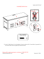
THIS INSTRUCTION BOOKLET CONTAINS IMPORTANT SAFETY INFORMATION.
PLEASE READ AND KEEP FOR FUTURE REFERENCE.
Whalen Furniture Mfg., Inc. Page 1 Factory No. 15548
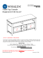
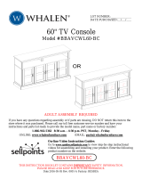
Table Top Console
Model # AVCEC54-AT
ADULT ASSEMBLY REQUIRED
If you have any questions regarding assembly or if parts are missing, DO NOT return this item to the
store where it was purchased. Please call our customer service number and have your instructions
and parts list ready to provide the model name, part name or factory number:
1-866-942-5362
Pacific Standard Time: 8:30 a.m. - 4:30 p.m., Monday - Friday
Or visit our web site 24 hours a day, 7 days a week for product assistance at
www.whalenstyle.com
Or e-mail your request to [email protected]
LOT NUMBER:
DATE PURCHASED:
/ /

Model # AVCEC54-AT
Please call for replacement parts or assistance: 1-866-942-5362
Whalen Furniture Mfg., Inc. Page 2 Factory No. 15548
MANUFACTURER: Whalen Furniture Mfg., Inc.
CATALOG: Table Top Console (AVCEC54-AT)
DATE OF MANUFACTURE: August 2013
MADE IN CHINA
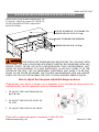
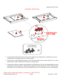
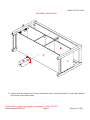
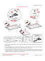
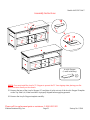
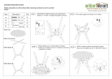
How to adjust the European adjustable hinges on doors
Shipping may cause doors to become out of alignment. If you find that the doors need to be
adjusted slightly, turn the appropriate screw as illustrated below.
1. TO ADJUST THE DOOR FORWARD OR
BACKWARD.
2. TO ADJUST THE DOOR TO RIGHT OR
TO LEFT.
3. TO ADJUST THE DOOR UP OR DOWN.
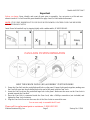
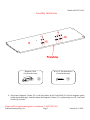
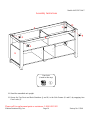
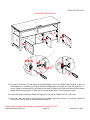
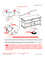
MAXIMUM RECOMMENDED WEIGHT LOADS
THIS UNIT IS NOT INTENDED FOR USE WITH CRT TVS. USE ONLY WITH
FLAT PANEL TVS AND AUDIO/VIDEO EQUIPMENT MEETING RECOMMENDED SIZE AND
WEIGHT LIMITS. NEVER USE WITH LARGER/HEAVIER THAN RECOMMENDED FLAT
PANEL TVS OR EQUIPMENT. TO AVOID INSTABILITY, PLACE FLAT PANEL TV IN THE
CENTER OF THE UNIT; CRT TVS, IMPROPERLY POSITIONED FLAT PANEL TVS, OR FLAT
PANEL TVS OR OTHER EQUIPMENT THAT EXCEED RECOMMENDED SIZE AND WEIGHT
LIMITS COULD FALL OFF OR BREAK THE UNIT
,
CAUSING POSSIBLE SERIOUS INJURY.
MAXIMUM LOAD 50 lb. (22.6 kg)
FITS UP TO MOST 60” FLAT PANEL TVs
MAXIMUM LOAD 135 lb. (61.2 kg)
PLACE TV BEHIND THE STOPPER

Model # AVCEC54-AT
Please call for replacement parts or assistance: 1-866-942-5362
Whalen Furniture Mfg., Inc. Page 3 Factory No. 15548
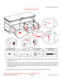
Important
Before you begin: Open, identify and count all parts prior to assembly. Lay out parts on a flat and non-
abrasive surface. You will need the parts identified on page 4 and 5 of this instruction manual.
NOTE:
IT IS VERY IMPORTANT TO USE GLUE WITH DOWELS. EXCESS GLUE CAN BE WIPED
OFF WITH DAMP CLOTH.
Insert Dowel at least half way by tapping lightly with a rubber mallet, IF NECESSARY.
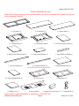
CAM LOCK SYSTEM OPERATION
HOW THE KNOCK DOWN (KD) ASSEMBLY SYSTEM WORKS
1. Screw the Cam Bolt into the pre-drilled small holes on the panel. Connect both panels together; making sure
the Cam Bolt goes into the pre-drilled hole at the end of the panel with the Cam Lock.
2. Insert the Cam Lock into the pre-drilled large hole in the panel. Make sure the arrow on the Cam Lock is
pointed towards the Cam Bolt.
3. Once the Cam Bolt is connected inside the Cam Lock, take a Phillips screwdriver (not included) and
tighten the Cam Lock clockwise.
4. Plug the Cam Lock Cover into the cross slot of the Cam Locks to conceal the cam.
You are now ready to assemble the KD unit.

Model # AVCEC54-AT
Please call for replacement parts or assistance: 1-866-942-5362
Whalen Furniture Mfg., Inc. Page 4 Factory No. 15548
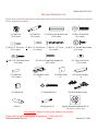
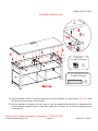
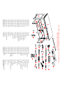
Parts and Hardware List
Please read completely through the instructions and verify that all listed parts and hardware are present
before beginning assembly.
A- Top Panel (1) B- Fixed Shelf (1) C- Bottom Panel (1)
D- Left Side Frame (1) E- Right Side Frame (1) F- Left Lower Partition Panel (1)
G- Right Lower Partition Panel (1) H- Upper Partition Panel (1) I- Upper Partition Molding (1)
J- Top Front Stretcher (1) K- Top Back Stretcher (1) L- Large Adjustable Shelf (2)
(With pilot holes for the back panel)
M- Small Adjustable Shelf (1) N- Left Door (1) O- Right Door (1)
P- Middle Door (1) Q- Back Panel (1) R- Support Foot w/Leveler (1) S- Cable Wheel (2)

Model # AVCEC54-AT
Please call for replacement parts or assistance: 1-866-942-5362
Whalen Furniture Mfg., Inc. Page 5 Factory No. 15548
Parts and Hardware List
Please read completely through the instructions and verify that all listed parts and hardware are present
before beginning assembly.
(1) Cam Lock (2) Cam Bolt (3) M8 x 30 mm Wood Dowel (4) M6 x 20 mm
Bolt
(30+1 extra) (30+1 extra) (35+1 extra) (4+1 extra)
(5) #6 x 1/2”
Zinc Screw (6) #6 x 1/2” Black Screw (7) #10 x 1-1/2” Screw (8) #5 x 1/2” Washer Head Screw
(12+1 extra) (3+1 extra) (6+1 extra) (6+1 extra)
(9
) #5 x 5/8” Pan Head Screw (10) M3 x 19 mm Ring Shank Nail (11) Cam Lock Cover
(6+1 extra) (24+1 extra) (32+1 extra)
(12) Shelf Pin (13) Magnetic Catch (14) Strike Plate (15) Acrylic Stopper
(12+1 extra) (3) (3) (1)
(16) Handle (4) (17) Handle Bolt (4) (18) Door Hinge (6 sets)
Glue (1) Touch-up Pen (1) Tipping Restraint Hardware Kit (2)
(Included in plastic bag)
Tools required: Phillips screwdriver and Hammer (not provided).

Model # AVCEC54-AT
Please call for replacement parts or assistance: 1-866-942-5362
Whalen Furniture Mfg., Inc. Page 6 Factory No. 15548
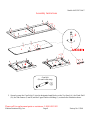
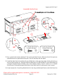
Assembly Instructions
1. Unpack the unit and confirm that you have all the hardware and required parts. Assemble the unit on a
carpeted floor or the empty carton to avoid any scratch.
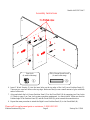
2. Position the Left and Right Side Frames (D and E) and the Right Lower Partition Panel (G) on a level
and protective surface with the holes facing up, as shown above.
3. Using the pilot holes as a guide, align and attach two Hinge Bases (18) onto the designated holes on the
Right Lower Partition Panel (G) and the hinge supports of the Side Frames (D and E). Make sure that
the middle slot of the Hinge Base will point towards the front of the unit when the unit is turned upright.
E
D
G
Door Hinge Base
(6 used in this step)
⑱

Model # AVCEC54-AT
Please call for replacement parts or assistance: 1-866-942-5362
Whalen Furniture Mfg., Inc. Page 7 Factory No. 15548
Assembly Instructions
4. Align three Magnetic Catches (13) to the pilot holes on the Fixed Shelf (B) with the magnetic plates
facing the finished edge. And then fasten the Magnetic Catches (13) in place using two 5/8” Pan Head
Screws (9) per catch.
B
Magnetic Catch
(3 used in this step)
⑬
#5 x 5/8” Pan Head Screw
(6 used in this step)
⑨

Model # AVCEC54-AT
Please call for replacement parts or assistance: 1-866-942-5362
Whalen Furniture Mfg., Inc. Page 8 Factory No. 15548
Assembly Instructions
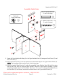
5. Securely screw the Cam Bolts (2) into the designated small holes on the Top Panel (A), the Fixed Shelf
(B), the Side Frames (D and E) and the Upper Partition Molding (I), as shown the illustration above.
E
B
A
I
2
Cam Bolt
(30 used in this step)
②

Model # AVCEC54-AT
Please call for replacement parts or assistance: 1-866-942-5362
Whalen Furniture Mfg., Inc. Page 9 Factory No. 15548
Assembly Instructions
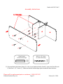
6. Insert 2 Wood Dowels (3) into the inner holes on the top edge of the Left Lower Partition Panel (F).
There are two cam bolt holes on the top edge. Make sure that you use a small amount of glue with both
ends of all dowels.
7. Align and attach the Left Lower Partition Panel (F) to the Fixed Shelf (B) by engaging two Cam Locks
(1) (Refer to page 3 on Cam Lock system operation supplement). As shown above. Make sure that the
finished edge of the Partition Panel (F) and the Fixed Shelf (B) point towards the same direction.
8. Repeat the same procedure to attach the Right Lower Partition Panel (G) to the Fixed Shelf (B).
B
1
1
G
F
M8 x 30 mm Wood Dowel
(4 used in this step)
③
Cam Lock
(4 used in this step)
①

Model # AVCEC54-AT
Please call for replacement parts or assistance: 1-866-942-5362
Whalen Furniture Mfg., Inc. Page 10 Factory No. 15548
Assembly Instructions
9. Fasten the Upper Partition Molding (I) to the Upper Partition Panel (H) using one Wood Dowel (3) and
two Cam Locks (1).
10. Insert two Wood Dowels (3) into the inner holes on the bottom edge of the Upper Partition Panel (H).
NOTE:
The long edge without cam bolt holes is the bottom edge.
11. Align the inserted Wood Dowels (3) under the assembled Upper Partition Panel (H) with the center
holes on the Fixed Shelf (B) and press them together. Ensure the Upper Partition Molding (I) points
towards the finished edge of the Fixed Shelf. Insert two 1-1/2”
Screws (7) through the drilled holes on
the Fixed Shelf (B) and securely screw into the bottom holes of the Upper Partition Panel (H).
G
F
B
H
I
1
H
I
M8 x 30 mm Wood Dowel
(3 used in this step)
③
#10 x 1-1/2” Screw
(2 used in this step)
⑦
Cam Lock
(2 used in this step)
①

Model # AVCEC54-AT
Please call for replacement parts or assistance: 1-866-942-5362
Whalen Furniture Mfg., Inc. Page 11 Factory No. 15548
Assembly Instructions
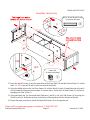
12. Align and attach the Bottom Panel (C) to the Lower Partition Panels (F and G) using four Wood Dowels
(3) and four 1-1/2” Screws (7). Make sure that the finished edges point towards the same direction.
F
C
3
3
Wood Dowel
(4 used in this step)
③
#10 x 1-1/2” Screw
(4 used in this step)
⑦

Model # AVCEC54-AT
Please call for replacement parts or assistance: 1-866-942-5362
Whalen Furniture Mfg., Inc. Page 12 Factory No. 15548
Assembly Instructions
13. Insert the Wood Dowels (3) into the inner holes of the Fixed Shelf (B) and the Bottom Panel (C) at both
ends. DO NOT insert the Wood Dowels into the Cam Bolt holes.
14. Align the drilled holes on the Left Side Frame (D) with the Wood Dowels (3) installed on the left end of
the last assembly and press them together. As shown above. Fasten the Left Side Frame (D) in place by
engaging four Cam Locks (1).
15. Align and attach the Top Front and Back Stretchers (J and K) to the Left Side Frame (D) by using two
Wood Dowels (3). Make sure the Cam Locks holes on the stretchers will face the back of the unit.
16. Repeat the same procedure to attach the Right Side Frame (E) at the opposite end.
K
C
E
D/E
J/K
3
3
D/E
B/C
1
Cam Lock
(8 used in this step)
①
M8 x 30 mm Wood Dowel
(12 used in this step)
③

Model # AVCEC54-AT
Please call for replacement parts or assistance: 1-866-942-5362
Whalen Furniture Mfg., Inc. Page 13 Factory No. 15548
Assembly Instructions
17. Tightly screw the Support Foot (R) into the threaded insert on the Bottom Panel (C) and set the attached
floor leveler to the correct height.
E

Model # AVCEC54-AT
Please call for replacement parts or assistance: 1-866-942-5362
Whalen Furniture Mfg., Inc. Page 14 Factory No. 15548
Assembly Instructions
18. Stand the assembled unit upright.
19. Secure the Top Front and Back Stretchers (J and K) to the Side Frames (D and E) by engaging four
Cam Locks (1).
E
D
1
1
1
Cam Lock
(4 used in this step)
①

Model # AVCEC54-AT
Please call for replacement parts or assistance: 1-866-942-5362
Whalen Furniture Mfg., Inc. Page 15 Factory No. 15548
Assembly Instructions
20. Insert the Wood Dowels (3) into the top holes of the last assembly. As shown above. DO NOT insert
the Wood Dowels into the Cam Bolt holes.
21. Ask for assistance to position the Top Panel (A) onto the inserted Wood Dowels (3) making sure the
Acrylic Stopper template locates at front side. Attach the Top Panel (A) in place by engaging twelve
Cam Locks (1).
A
H
M8 x 30 mm Wood Dowel
(12 used in this step)
③
Cam Lock
(12 used in this step)
①

Model # AVCEC54-AT
Please call for replacement parts or assistance: 1-866-942-5362
Whalen Furniture Mfg., Inc. Page 16 Factory No. 15548
Assembly Instructions
22. Now, go back and securely tighten all Cam Locks and Wood Screws. Make sure that all the parts are
tight and there are no gaps between the parts. This will help keep the unit square.
23. Unfold the Back Panel (Q) and align the pre-drilled holes on the upper long edge with the pilot holes on
the Top Back Stretcher (K). Make sure that the drilled holes for Cable Wheels (S) on the Back Panel (Q)
overlap the threaded inserts included on the Lower Partition Panels (F and G). Insert six 1/2” Washer
Head Screws (8) through the upper drilled holes on the Back Panel (Q) and securely screw in place.
24. Gently hammer the 19 mm Ring Shank Nails (10) into the pre-drilled small holes on the Back Panel (Q).
Q
10
A
Q
Q
8
19 mm Ring Shank Nail
(24 used in this step)
⑩
1/2” Washer Head Screw
(6 used in this step)
⑧

Model # AVCEC54-AT
Please call for replacement parts or assistance: 1-866-942-5362
Whalen Furniture Mfg., Inc. Page 17 Factory No. 15548
Assembly Instructions
25. Attach 2 Cable
Wheels (S) to the backside of the unit with four M6 x 20 mm Bolts (4) provided. You
can use the Cable
Wheels to organize your cables and cords.
Q
M6 x 20 mm Bolt
(4 used in this step)
④

Model # AVCEC54-AT
Please call for replacement parts or assistance: 1-866-942-5362
Whalen Furniture Mfg., Inc. Page 18 Factory No. 15548
Assembly Instructions
26. Position the 3 Door Panels (N, O and P) on a level and protective surface with the cut out facing up, as
shown above.
27. Extend the Hinges Arms (18) and rest the Hinge Cups onto the cutouts of the Door Panels (N, O and P).
Secure the Hinge Arms in place by using two 1/2”
Zinc Screws (5) in each.
28. Using the pilot hole as a guide, fasten one Strike Plate (14) to the upper corner of each Door Panel (N,
O and P) with the 1/2”
Black Screw (6). Make sure that the Strike Plates (14) will properly match the
Magnetic Catches (13) installed on the Fixed Shelf (B).
Strike Plate
(3 used in this step)
⑭
1/2” Black Screw
(3 used in this step)
⑥
1/2” Zinc Screw
(12 used in this step)
⑤
Hinge Arm
(6 used in this step)
⑱
N
O
P
14
6
N/O/P
N/O/P

Model # AVCEC54-AT
Please call for replacement parts or assistance: 1-866-942-5362
Whalen Furniture Mfg., Inc. Page 19 Factory No. 15548
Assembly Instructions
29. Pick up the Left Door (N) and attach the extended Hinge Arms to the Hinge Bases installed on the Left
Side Frame (D). Loosen the lock bolt on the back of Hinge Base for an easy fit. Align and insert the “U”
slot on Hinge Arm under the lock bolt head on the back of Hinge Base. Make sure that both door hinges
engage and function properly. Tighten the bolt on the Hinge Base to lock the hinges in place.
30. Repeat the same procedure to attach the Right Door (O) and the Middle Door (P) to the unit.
31. Open and close the doors to make sure they are aligned and shut correctly. If necessary, adjust the
screws for a good fit (refer to the supplement on page 2).
N
P
O
A
N/O/P
1
1

Model # AVCEC54-AT
Please call for replacement parts or assistance: 1-866-942-5362
Whalen Furniture Mfg., Inc. Page 20 Factory No. 15548
Assembly Instructions
32. Attach the Door Handles (16) to the front side of the Door Panels (N, O and P) with the provided
Handle Bolts (17).
33. With the doors open, insert four Shelf Pins (12) into the desired holes in the sides of each lower
compartment. Make sure you place the four Shelf Pins in the same level so the shelf is not tilted. Tilt
and rest the Adjustable Shelves (L and M) onto the Shelf Pins (12) with the finished edge facing the
front of the unit.
34. Plug the Cam Lock Covers (11) onto the visible Cams Locks to conceal the Cam Locks.
L
L
M
N/O/P
L/M
12
Shelf Pin
(12 used in this step)
⑫
Cam Lock Cover
(32 used in this step)
⑪
Handle Bolt
(4 used in this step)
⑰
Door Handle
(4 used in this step)
⑯
Page is loading ...
Page is loading ...
Page is loading ...
Page is loading ...
-
 1
1
-
 2
2
-
 3
3
-
 4
4
-
 5
5
-
 6
6
-
 7
7
-
 8
8
-
 9
9
-
 10
10
-
 11
11
-
 12
12
-
 13
13
-
 14
14
-
 15
15
-
 16
16
-
 17
17
-
 18
18
-
 19
19
-
 20
20
-
 21
21
-
 22
22
-
 23
23
-
 24
24


Ask a question and I''ll find the answer in the document
Finding information in a document is now easier with AI
Related papers
-
 Whalen JCS110245-H-US User manual
-
 Whalen WS3060926FP Operating instructions
-
 Whalen JCS110245-D-US User manual
-
 Whalen WS03061533 User manual
-
 Whalen BBAVCWL60-BC User manual
-
 Whalen BBHC60DBC User manual
-
 Whalen JCS110243-I-US User manual
-
 Whalen BBAVCD54N User manual
-
 Whalen ECOM-KDS User manual
-
 Whalen MFC-23 User manual


Other documents
-
 Outdoor Interiors 30110NA Operating instructions
-
ANGELES HOME M66-8HW205GR User manual
-
 Furniture of America IDF-AC291BK-3 Installation guide
-
 Furniture of America IDF-AC535CPN Installation guide
-
 Furniture of America IDF-AC534 Installation guide
-
Unbranded 1062200910 Operating instructions
-
ROOMS TO GO 23811234 Assembly Instructions
-
-
-
Home Decorators Collection 1590000410 Installation guide


