Page is loading ...
Page is loading ...
Page is loading ...
Page is loading ...

Ausgabe/ Edition:
12/2011
Anbauanleitung 580
Gimpenüberwachung, Teilesatz 0580 591684 VES
Fitting instructions 580
Gimp monitoring, Kit 0580 591684 VES
Teile-Nr. / Part-No.:
0791 580714
Änderungsindex
Rev. index:
00.0
Blatt: von
Sheet: 5 from 8
Printed in Germany
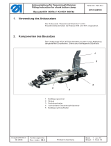
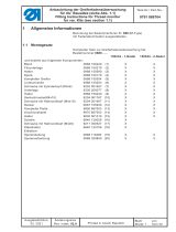
1 Kit components
The kit can be mounted onto the following subclasses:
580-141-01
580-341-01
The kit consists of the following components:
Quantity Designation Material-No.
9815 710103 1 Inductive sensor complete
9870 580006 1 Cable set complete
9840 121001 3 Cable ties
0580 490300 1 Angle
0580 351310 1 Gimp guide
0580 351260 1 Leaf spring
9202 002077 2 Cylinder head screws M4 x 10
9330 000087 2 Washers A4,3
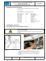
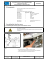
2 Assembling the inductive sensor
2.1 Assembling the fastening angle and the inductive sensor
– The fastening angle 1 is fixed on the base stand 2.
In order to do so two bore holes with M4 thread have to be drilled.
– Create a drilling template 3 according to sketch 1.
Caution: Risk of injury!
Turn off the main switch!
Mount the fastening angle and the inductive sensor only with the machine
switched off.
fig. 1 fig
. 2
2
4
1
3

Ausgabe/ Edition:
12/2011
Anbauanleitung 580
Gimpenüberwachung, Teilesatz 0580 591684 VES
Fitting instructions 580
Gimp monitoring, Kit 0580 591684 VES
Teile-Nr. / Part-No.:
0791 580714
Änderungsindex
Rev. index:
00.0
Blatt: von
Sheet: 6 from 8
Printed in Germany
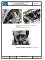
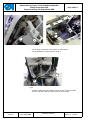
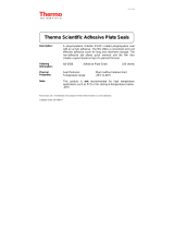
– Fix the angle 1 with two screws M4 x 10 and washers.
– Fix the inductive sensor 5 onto the angle 1.
fig. 5
– Install the cable 6 of the inductive sensor and fix it onto the cable
harness with the cable ties and connect it to the PCB 7.
fig. 3 fig. 4
1
5
4
1
6
7

Ausgabe/ Edition:
12/2011
Anbauanleitung 580
Gimpenüberwachung, Teilesatz 0580 591684 VES
Fitting instructions 580
Gimp monitoring, Kit 0580 591684 VES
Teile-Nr. / Part-No.:
0791 580714
Änderungsindex
Rev. index:
00.0
Blatt: von
Sheet: 7 from 8
Printed in Germany
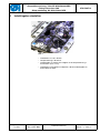
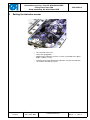
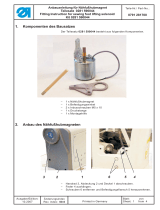
3 Setting the inductive sensor
fig. 6
– Turn the hook turret 180°.
– Lower the gimp guide 1.
– Approach the inductive sensor 5 as close as possible to the gimp
guide 1 (about 0.3 mm).
– Continue turning the hook turret and make sure that the inductive
sensor does not abut anywhere.
5
1

Ausgabe/ Edition:
12/2011
Anbauanleitung 580
Gimpenüberwachung, Teilesatz 0580 591684 VES
Fitting instructions 580
Gimp monitoring, Kit 0580 591684 VES
Teile-Nr. / Part-No.:
0791 580714
Änderungsindex
Rev. index:
00.0
Blatt: von
Sheet: 8 from 8
Printed in Germany
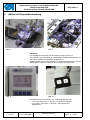
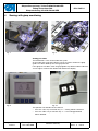
4 Sewing with gimp monitoring
Sewing procedure
The buttonhole is sewn to the end of the eyelet.
At the end of the eyelet the inductive sensor 5 checks whether the gimp
guide 1 has been lifted by the sewn gimp thread.
If the gimp has not been sewn the gimp guide stays down and the inductive
sensor signals a failure that will be indicated on the display.
The operator can decide how to continue.
– Press the "OK" key or function key "2" = sewing will be continued.
– Press the "ESC" key or function key "1" = the sewing procedure
will be aborted.
fig. 7 fig. 8
fig. 9 fig.
10
5
1
-
 1
1
-
 2
2
-
 3
3
-
 4
4
-
 5
5
-
 6
6
-
 7
7
-
 8
8


Ask a question and I''ll find the answer in the document
Finding information in a document is now easier with AI
in other languages
- Deutsch: DURKOPP ADLER 580 Benutzerhandbuch
Related papers
-
Duerkopp Adler 580 User manual
-
-
-
Duerkopp Adler 869-M User manual
-
Duerkopp Adler 175 User manual
-
 Duerkopp Adler 911-211 User manual
-
 Duerkopp Adler 867 User manual
-
 Duerkopp Adler 530 User manual
-
 Duerkopp Adler 550-867 s User manual
-


Other documents
-
Gimp Version 2.2 User manual
-
 Thermo Fisher Scientific Adhesive Plate Seal User guide
-
 Duerkopp Adler 581 Operating instructions
-
 Duerkopp Adler 281 User manual
-
 Duerkopp Adler 581 Operating instructions
-
 Duerkopp Adler 506-3 User manual
-
 Duerkopp Adler 581 User manual
-
 Duerkopp Adler 888 User manual
-
 Duerkopp Adler 581 User manual
-
ABB CP650-WEB-x Operating Instructions Manual


