Page is loading ...


QUAD
http://www.zennio.com Technical Support: http://support.zennio.com
2
CONTENTS
Contents ........................................................................................................................................ 2
Document Updates ....................................................................................................................... 3
1 Introduction .......................................................................................................................... 4
1.1 QUAD ............................................................................................................................. 4
1.2 Installation ..................................................................................................................... 5
2 Configuration......................................................................................................................... 7
2.1 General .......................................................................................................................... 7
2.2 Security Binary Inputs ................................................................................................... 8
2.3 Thermostats ................................................................................................................ 11
3 ETS Parameterisation .......................................................................................................... 12
3.1 Default Configuration .................................................................................................. 12
3.2 General Screen ............................................................................................................ 12
3.2.1 Binary Input ..................................................................................................... 13
3.2.2 Temperature Probe ......................................................................................... 24
3.2.3 Motion Detector .............................................................................................. 26
3.3 Thermostats ................................................................................................................ 27
ANNEX I. Communication Objects............................................................................................... 28

QUAD
http://www.zennio.com Technical Support: http://support.zennio.com
3
DOCUMENT UPDATES
Version
Changes
Page(s)
[5.3]_a
Changes in the application program:
• Internal optimisation of the thermostat functions.
-
Correction in the functional range of
special mode selection
objects shown in the object table.
31 - 32
[5.2]_a
Changes in the application program:
• Temperature protection:
increased range for the
temperature values.
-
[5.1]_a
Changes in the application program:
• Thermostat
: possibility of periodically sending, if
configured, the control variable of the currently inactive
mode
(parameter: “Send both H/C control signals
periodically?”).
• Thermostat
: restriction to prevent sending the
additional heat/cool orders when they are not
necessary.
• Motion sensor
: new parameter to restart the luminosity
for a certain time after a no-detection.
-
[5.0]_a
Changes in the application program:
•
Security function added to the switch/sensor binary
inputs to allow the detection of breakdown / sabotage
situations.
-

QUAD
http://www.zennio.com Technical Support: http://support.zennio.com
4
1 INTRODUCTION
1.1 QUAD
QUAD is an analogue / digital input module from Zennio featuring four separate inputs,
each configurable as:
Binary Input.
Inputs configured as binary inputs can be connected a conventional,
potential-free pushbutton, a switch or a binary sensor.
It is also possible to detect breakdown and sabotage situations in the input
lines by enabling the security functions for the binary inputs.
Temperature Probe.
Inputs configured as a temperature probe can be connected a temperature
sensor (such as models ZN1AC-NTC68 S/E/F and SQ-AmbienT from
Zennio), which will allow QUAD monitor the room temperature.
Motion Detector.
Inputs configured as motion detectors need to be connected a Zennio motion
sensor (model ZN1IO-DETEC), which will allow QUAD monitor presence or
luminosity changes in a room.
Moreover, QUAD implements four independent thermostats, which can be enabled
and configured separately.
Figure 1. QUAD

QUAD
http://www.zennio.com Technical Support: http://support.zennio.com
5
1.2 INSTALLATION
QUAD is connected to the KNX bus through the incorporated terminal connector, while
the input lines need to be connected to QUAD through the screw terminal block,
bundled with the packaging of the device.
Once powered through the KNX bus, the device may be downloaded both an individual
address or the application program.
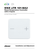
Figure 2 shows the connection diagram of QUAD.
Figure 2. Element diagram
The main elements are described next:
Programming Button: a short press on this button sets the device into the
programming mode, making the associated LED (2) light in red. If this button
is held at the same time of applying bus power to the device, QUAD will enter
the Safe Mode. In such case, the LED will intermit in red.
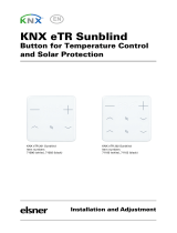
Slots for the Input Lines: insertion slot for the input terminal block (Figure
3), which is required for the connection of the input lines (1-4) to QUAD. For
proper results, the terminals from the external elements (pushbutton, switch,
sensor, temperature probe or motion sensor) should be connected on the one
hand to the corresponding numbered connection point (1-4) of the terminal
block, and on the other hand to any of the two common connection points
(labeled as “C”), which are internally connected, which makes them
equivalent to each other.
1.- KNX Bus Connector
2.- Programming LED
3.- Programming Button
4.- Slot for the Input Lines

QUAD
http://www.zennio.com Technical Support: http://support.zennio.com
6
Figure 3. Input terminal block
To obtain further information about the technical features of QUAD and on security
and installation procedures, please refer to the Datasheet of the device, bundled
with the original packaging and also available at the http://www.zennio.com
website.

QUAD
http://www.zennio.com Technical Support: http://support.zennio.com
7
2 CONFIGURATION
2.1 GENERAL
The QUAD analogue/digital input controller from Zennio is a multi-function device
featuring four input ports, each of them configurable as:
Binary Input,
Temperature Probe,
Motion sensor.
Therefore, QUAD makes it possible to connect different external elements as long as
they match any of the above categories: pushbuttons, switches, temperature probes,
motion sensors (model ZN1IO-DETEC from Zennio)…
Inputs configured as binary should be distinguished into pushbuttons and
switches/sensors (depending on the connected element). Each of these two have
their own configurable parameters, as described in section 3 of this manual.
Inputs configured as temperature probes can be customised through a set of
parameters related to how the temperature value is measured and sent to the bus.
On their side, inputs configured as motion sensors offer up to three virtual channels
each, which allows performing different actions upon detection and no-detection events
on the corresponding input. As a result of the motion detection / no-detection, each
channel will send the corresponding objects to the KNX bus, unless the channel is
found to be locked.
The motion sensor also features a luminosity sensor, which may be configured in
QUAD to send the detection / no-detection objects depending on the measured
luminosity level and according to the previously calibrated levels.

QUAD
http://www.zennio.com Technical Support: http://support.zennio.com
8
2.2 SECURITY BINARY INPUTS
Binary inputs configured as an switch / sensor offer the option to enable a security
function, in order to detect breakdown or sabotage events that may arise in the system.
This security function relies on the insertion of an end-of-line resistor, and on
continuously monitoring the state of such line, so any unexpected situation can be
detected.
Important: any of the resistors shown in Table 1 can be installed, although it is
advisable that the power permitted by the resistor (manufacturers and vendors typically
provide with this information) is at least 0.25 W. Note that the value of the selected
resistor should be also set by parameter in ETS.
Value (Ohms)
Minimum recommended power (W)
2200 Ω (±10%)
¼ W
2700 Ω (±10%)
3300 Ω (±10%)
4700 Ω (±10%)
10000 Ω (±10%)
Table 1. End-of-line resistor permitted values
Two different use cases can be distinguished:
Normally Closed (N.C.) Switch / Sensor: the circuit remains typically closed
and is only opened in the event of an interruption or a detection in the sensor.
The selected resistor should be connected to the circuit line in series, and as
closer as possible to the switch/sensor, preferably in touch with its terminals
and hardly accessible from outside. See Figure 4.
Figure 4. Normally closed switch/sensor. Resistor in series
In the event of a short-circuit in the line, QUAD will set the alarm object of
the corresponding input to “1”, and will then send it periodically to the bus
N.C. S/S

QUAD
http://www.zennio.com Technical Support: http://support.zennio.com
9
until the situation is over, as the short-circuit is interpreted to be due to a
sabotage or a breakdown.
Figure 5. Short-circuit (normally closed S/S)
In the event of an open circuit in the line, QUAD will interpret it as a
regular falling edge (i.e., as an interruption or a detection in the
switch/sensor), so only the value parameterised for such edge will be sent
to the bus.
Figure 6. Open circuit (normally closed S/S)
Normally Open (N.O.) Switch / Sensor: the circuit remains typically open
and only becomes closed in the event of an interruption or a detection in the
switch/sensor. The selected resistor should be connected to the circuit line in
parallel, and as closer as possible to the switch/sensor, preferably in touch
with its terminals and hardly accessible from outside. See Figure 7.
Figure 7. Normally open switch/sensor. Parallel resistor
In the event of a short-circuit in the line, QUAD will interpret it as a
regular rising edge (i.e., as an interruption or a detection in the
N.C. S/S
N.C. S/S
N.O. S/S

QUAD
http://www.zennio.com Technical Support: http://support.zennio.com
10
switch/sensor), so only the value parameterised for such edge will be sent
to the bus.
Figure 8. Short-circuit (normally open S/S)
In the event of an open circuit in the line, QUAD will set the alarm object
of the corresponding input to “1”, and will then send it periodically to the
bus until the situation is over, as the open circuit is interpreted to be due to
a sabotage or a breakdown.
Figure 9. Open circuit (normally open S/S)
By means of this security function in the switch/sensor binary inputs, QUAD is also able
to analyse the voltage levels of the system. In case they are found to be unstable
(e.g., due to the coupling of other lines), QUAD will activate the alarm object of the
corresponding input and send the activation value to the bus periodically, until such
event is over.
Additionally, QUAD offers the possibility of connecting multiple switches / sensors to
the same input (so that a certain function can be alternatively controlled from one or
another), provided that they are of the same type: normally open or normally closed. In
case this option needs to be combined with the security function, it is important to keep
in mind that only one end-of-line resistor should be installed (in other words: only to
one of the switches / sensors connected to the same input).
N.O. S/S
N.O. S/S

QUAD
http://www.zennio.com Technical Support: http://support.zennio.com
11
2.3 THERMOSTATS
QUAD allows independently enabling and configuring up to four thermostat functions,
with independence of the number of the inputs that have been configured.
How the Zennio thermostat works and is configured is described in an specific
document, Zennio Building Thermostat, available at the http://www.zennio.com
website.

QUAD
http://www.zennio.com Technical Support: http://support.zennio.com
12
3 ETS PARAMETERISATION
To begin with the parameterisation process of QUAD it is necessary, once the ETS
software has been opened, to import the corresponding product database.
Next, the device is inserted into the project where desired and, after right-clicking on its
name, the “Edit parameters” option should be selected to start the process.
The next sections show the parameterisation process in detail, and the different
functions provided by QUAD.
3.1 DEFAULT CONFIGURATION
When entering the parameter edition of QUAD for the first time, the following window
will be shown:
Figure 10. Default parameterisation window
As shown in Figure 10, the four inputs of the device are disabled by default. It is
necessary to enable and configure them independently.
The Thermostats tab is also visible by default. It permits enabling and configuring the
four available thermostats, which are disabled by default.
No communication objects are displayed by default. They will become visible as the
different functions of the device are enabled by the integrator.
3.2 GENERAL SCREEN
This window brings the option to enable and configure the different input ports of
QUAD.

QUAD
http://www.zennio.com Technical Support: http://support.zennio.com
13
Figure 11. Enabling an input
Depending on the selected input type, additional parameter windows may become
visible, as explained next.
3.2.1 BINARY INPUT
An input configured as binary can be connected both a push button or a switch/sensor.
Depending on the binary input type, different configuration options will be displayed.
Figure 12. Binary input
3.2.1.1 PUSH BUTTON
From the specific tab enabled after selecting “push button” for the enabled binary input
(see Figure 13) it will be possible to customise how QUAD reacts on the detection of
presses.
Figure 13. Binary input: push button

QUAD
http://www.zennio.com Technical Support: http://support.zennio.com
14
SHORT PRESS: sets the type of the action to be performed when a short
press takes place on the push button connected to the input of QUAD:
No Action. No action is performed.
Sending of 0/1. A new tab becomes visible to let the integrator set (under
“Response”) the value to be sent to the KNX bus when a short press
happens:
Figure 14. Sending of 0/1
• “0”: the “[Ix] [Short Press] 0” 1-bit communication object is
enabled, and sent to the KNX bus (with the value “0”) on every
press.
• “1”: the “[Ix] [Short Press] 1” 1-bit communication object is
enabled, and sent to the KNX bus (with the value “1”) on every
press.
• “Switching 0/1”: the “[Ix] [Short Press] Switching” 1-bit
communication object is enabled, and sent to the KNX bus with
the values “1” and “0” alternating after every press.
The transmission of these values can be performed cyclically, i.e., it is
possible to periodically re-send them (the 0s, or the 1s, or both) if
configured. If such option is required, the “Cyclical Response Sending”
parameter needs to be enabled, which will bring an additional parameter
(“Cycle time”) to set a certain time (1-255 seconds).
Shutter Control. This function allows sending the KNX bus a 1-bit object
for shutter control. Under the “Response” parameter in the tab that shows
up after selecting this function, it is possible to select the particular order to
be sent on a short press:

QUAD
http://www.zennio.com Technical Support: http://support.zennio.com
15
Figure 15. Shutter control
• Up: the “[Ix] [Short Press] Move Up Shutter” 1-bit object is enabled,
and sent to the KNX bus (with the value “1”) so that the shutter is
moved up.
• Down: the “[Ix] [Short Press] Move Down Shutter” 1-bit object is
enabled, and sent to the KNX bus (with the value “0”) so that the shutter
is moved down.
• Up/down (switched): the “[Ix] [Short Press] Move Up/Down Shutter”
1-bit object is enabled, and sent to the KNX bus with the values “1” and
“0” alternating, so the move up and move down orders can be sent with
a sole push button.
• Stop/Step Up: the “[Ix] [Short Press] Stop/Step Up Shutter” 1-bit
object is enabled, and sent to the KNX bus (with the value “0”) in order
to stop the shutter. In case the shutter is not in motion and if slats /
lamellas are available, this value will be interpreted as an order to move
them one step upwards.
• Stop/Step Down: the “[Ix] [Short Press] Stop/Step Down Shutter” 1-
bit object is enabled, and sent to the KNX bus (with the value “1”) in
order to stop the shutter. In case the shutter is not in motion and if slats
/ lamellas are available, this value will be interpreted as an order to
move them one step downwards.
• Stop/Switched Step: the “[Ix] [Short Press] Stop/Step Shutter
(switched)” 1-bit object is enabled, and sent to the KNX bus (with the
values “1” and “0” alternating with every press) in order to stop the
shutter. In case the shutter is not in motion and if slats / lamellas are
available, this value will be interpreted as an alternating order to move
them one step downwards or upwards.

QUAD
http://www.zennio.com Technical Support: http://support.zennio.com
16
Dimmer Control. This functions allows sending the KNX bus a
communication object to control light-dimming devices. Under the
“Response” parameter in the tab enabled after selecting this function, it is
possible to set the particular order to be sent:
Figure 16. Dimmer
• Light ON: the “[Ix] [Short Press] Dimmer ON” 1-bit object is enabled,
and sent to the KNX bus (with the value “1”) so that the light is turned
on by the dimmer.
• Light OFF: the “[Ix] [Short Press] Dimmer OFF” 1-bit object is
enabled, and sent to the KNX bus (with the value “0”) so that the light is
turned off by the dimmer.
• Light ON/OFF (switched): the “[Ix] [Short Press] Dimmer ON/OFF”
1-bit object is enabled, and sent to the KNX bus with the values “1” and
“0” alternating with every press, so that the light can be turned on and
off with a sole push button.
Note: this function works in the same terms both if applied to short
presses or to long presses: every time a button press is detected, a
different order will be sent (switch-on / switch-off), while no orders will
be sent at all when the button is released.
• Brighter: the “[Ix] [Short Press] Brighter” 4-bit object is enabled, and
sent to the KNX bus so that the light level is increased by the
parameterised step (“Dimming step” parameter, according to Table 2).
On the first short press, a light increase order will be sent, while on the
second press an order to interrupt the regulation will be sent. Further
presses will repeat the same sequence.

QUAD
http://www.zennio.com Technical Support: http://support.zennio.com
17
Dimming step
Presses required for the
entire regulation (0% – 100%)
100% 1
50% 2
25% 4
12,5%
8
6,25%
16
3,1%
32
1,5% 64
Table 2. Dimming steps
• Darker: the “[Ix] [Short Press] Darker” 4-bit object is enabled, and
sent to the KNX bus so that the light level is decreased by the
parameterised step (“Dimming step” parameter, according to Table 2).
On the first short press, a light decrease order will be sent, while on the
second press an order to interrupt the regulation will be sent. Further
presses will repeat the same sequence.
• Brighter/Darker (switched): the “[Ix] [Short Press] Brighter/Darker”
4-bit object is enabled, and sent to the KNX bus alternatively with the
orders to increase or to decrease the light level by the parameterised
step (“Dimming step” parameter, according to Table 2), although a
stop order is inserted between every two dim orders.
Note: if this function is parameterised for the short presses, the orders
sent to the bus on every press will commute according to the following
sequence increase – stop – decrease – stop – increase… However, if
assigned to long presses, the stop orders will be sent once the button is
released, while the alternating increase / decrease orders will always be
sent as soon as a new press is detected. The following example
illustrates this:
Example:
An input configured as push button is assigned the switched brighter/darker function
with a dimming step of 12.5%.
In the case of the short presses, the behaviour is as follows:
1
st
Press:

QUAD
http://www.zennio.com Technical Support: http://support.zennio.com
18
As the button gets pressed, nothing happens.
Once the button is released, the “increase by 12.5%” order is sent.
2
nd
Press:
As the button gets pressed, nothing happens.
Once the button is released, the “stop” order is sent.
3
rd
Press:
As the button gets pressed, nothing happens.
Once the button is released, the “decrease by 12.5%” order is sent.
4
th
Press:
As the button gets pressed, nothing happens.
Once the button is released, the “stop” order is sent.
5
th
Press:
As the button gets pressed, nothing happens.
Once the button is released, the “increase by 12.5%” order is sent.
…
On the contrary, in the case of the long presses, the behaviour is as follows:
1
st
press:
As the button gets pressed, the “increase by 12.5%” order is sent.
Once the button is released, the “stop” order is sent.
2
nd
press:
As the button gets pressed, the “decrease by 12.5” order is sent.
Once the button is released, the “stop” order is sent.
3
rd
press:
As the button gets pressed, the “increase by 12.5%” order is sent.
Once the button is released, the “stop” order is sent.
…

QUAD
http://www.zennio.com Technical Support: http://support.zennio.com
19
Note: the aim of step dimming is letting the user perceive a gradual
transition of the light level, with the option of interrupting the regulation
when the desired level is reached. Therefore, it is advisable to
parameterise a dimming step of 100%, so that a sole press (i.e., with no
need of further presses) is enough to step through all the possible light
levels, interrupting the regulation when desired.
Sending of a Scene. This function allows sending the KNX bus a 1-byte
communication object for scene control. Under the “Response” parameter
in the tab that becomes visible after selecting this function, it is possible to
select the particular action to be performed on every press.
Figure 17. Scenes
• Run Scene: the “[Ix][Short Press] Run Scene” 1-byte communication
object is enabled, and sent to the KNX bus with a value (1 to 64, as
configured through the Scene parameter and decreased by one) that
will run the corresponding scene.
• Save Scene: the “[Ix][Short Press] Save Scene” 1-byte
communication object is enabled, and sent to the KNX bus with a
certain scene value (the one set for the Scene parameter, and
increased by 127, according to the KNX standard) so that it is
interpreted as an order to overwrite the configuration of such scene with
the current states.
LONG PRESS: allows defining a certain action to be performed whenever a
long press occurs in the push button connected to the input port of QUAD.
The available options are analogous to those already described for the short
press case, although certain differences apply to the dimmer control, as
already stated.
THRESHOLD TIME: sets the minimum time (in tenths of a second) the push
button needs to stay pressed so that QUAD interprets it as a long press.

QUAD
http://www.zennio.com Technical Support: http://support.zennio.com
20
RESPONSE DELAY (after short press): sets a certain delay time (in tenths
of a second) that QUAD will wait for, prior to sending the communication
objects corresponding to the response parameterised for short presses. In
other words, after a short press, QUAD will wait for the configured delay
before sending the corresponding value to the bus. Should this response
need to be immediate, this parameter must be set to “0”.
RESPONSE DELAY (after long press): sets a certain delay time (in tenths
of a second) that QUAD will wait for, prior to sending the communication
objects corresponding to the response parameterised for long presses. In
other words, after a long press, QUAD will wait for the configured delay
before sending the corresponding value to the bus. Should this response
need to be immediate, this parameter must be set to “0”.
LOCK: enables the “[Ix] Lock” 1-bit object, which, on the reception of the
value “1”, locks the input line, so that any press that takes place is ignored.
Once the value “0” is received, the input is unlocked back.
Actions/presses that may occur while the input is locked will not be taken into
account after the input is unlocked again.
3.2.1.2 SWITCH/SENSOR
Figure 18. Switch/sensor
From the tab that becomes visible after setting a binary input as a switch/sensor (see
Figure 18) it is possible to customise how QUAD should behave regarding the signals
received from the switch/sensor connected to the input port.
/