Page is loading ...

Released 5/95 714
Vickers
®
General Product Support
SMC20 Motion Controller

1
Contents
Description . . . . . . . . . . . . . . . . . . . . . . . . . . . . . . . . . . . . . . . . . . . . . . . . . . . . . . . . . . . . . . . . . . . . . . . . . . . . . . . . . . . . . . . . . . . . . . . . . . . 2
Features . . . . . . . . . . . . . . . . . . . . . . . . . . . . . . . . . . . . . . . . . . . . . . . . . . . . . . . . . . . . . . . . . . . . . . . . . . . . . . . . . . . . . . . . . . . . . . . . . . . . . 3
Front Panel . . . . . . . . . . . . . . . . . . . . . . . . . . . . . . . . . . . . . . . . . . . . . . . . . . . . . . . . . . . . . . . . . . . . . . . . . . . . . . . . . . . . . . . . . . . . . . . . . . . 4
Communication Interface . . . . . . . . . . . . . . . . . . . . . . . . . . . . . . . . . . . . . . . . . . . . . . . . . . . . . . . . . . . . . . . . . . . . . . . . . . . . . . . . . . . . . . . 4
Specifications . . . . . . . . . . . . . . . . . . . . . . . . . . . . . . . . . . . . . . . . . . . . . . . . . . . . . . . . . . . . . . . . . . . . . . . . . . . . . . . . . . . . . . . . . . . . . . . . . 5
Installation . . . . . . . . . . . . . . . . . . . . . . . . . . . . . . . . . . . . . . . . . . . . . . . . . . . . . . . . . . . . . . . . . . . . . . . . . . . . . . . . . . . . . . . . . . . . . . . . . . . . .6

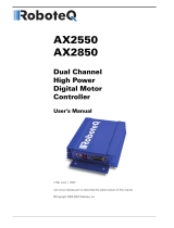
Figure 1.1 SMC20 Front Panel
2
Description
The Vickers SMC20 is a stand-alone,
two-axis precision motion controller. It
has a built-in electrical power supply,
and connects to several other
components in a typical motion control
system:
D A power source.
D A motion actuator for each axis: (any
combination of the following)
– a drive amplifier and electric servo
motor, or
– a hydraulic servo valve and cylinder
or motor.
– a hydraulic proportional valve and
amplifier with cylinder or motor.
D A position feedback sensor for each
axis of motion.
In addition, the SMC20 includes
communication ports for connecting it to
the Hand-Held User Terminal and
printer.
The motion controller occupies an
8″ x 3.5″ x 11.5″ case that can be
mounted in any standard NEMA-type
cabinet or mounted flat using the
optional hinge mounting.
Figure 1.1 shows the front panel and
connections.
Features
The SMC20 motion controller presents
several features:
D High performance for electric and
hydraulic motion control applications.
D Two-axis event coordination capability
linked via programmable digital I/O.
D Power supply, controller, and
programmable I/Os in one package.
D Hand-Held Operator Interface
D Dual processor design – 16 bit
interface microprocessor and 32 bit
digital signal processor.
D Plug-in option boards for position
sensors and communications.
D Discrete, programmable digital I/O.
D +
10 V differential or single–ended
output.
D 0+24 mA, 0+50 mA, 0+100 mA output
command. (optional) (Model code
selectable)
D Proportional, integral, and derivative
(PID) compensation
D Direction sensitive gains to
compensate for unequal area
cylinders. Also Dither and Gain Break
are available in Hydraulic mode.
D Programmability in standard
engineering units.
D Ability to change gains within a profile
to compensate for load changes, etc.

Figure 1-2. User Interface Terminal
3
Front Panel
The SMC20 front panel provides all the
controller’s connections to the motion
control system. Refer to Figure 1-1 to
locate the connections (viewed from top
to bottom; left column, center column,
right column):
Left Column
D Power input (120 VAC @ 2A)
D Isolated DC supply; 24 Volts,
unregulated.
D Power ‘On’ LED indicators.
D Fuse.
Center Column
D Axis 1 (X)
D “Enable” and “CPU” LED indicators.
D Common system. (Opto-isolation
power, enable, etc.)
D Axis 2 (Y)
Right Column
D Axis 1 (X) position sensor.
D Axis 2 (Y) position sensor.
D RS232C communication port.
D RS422/485 communication port.
Axis 1 (X) and Axis 2 (Y) connections
each include pins for eight inputs and
eight outputs. These inputs/outputs are
digital.
LED indicators immediately adjacent to
Axis 1 and Axis 2 connections show
which pins are active.
Communication Interface
Communication between an operator
and the SMC20 occurs through the
communication interface, a board that
plugs into the controller.
The standard communication interface
provides two serial ports – RS232C and
RS422/485. The RS422/485 port is
dedicated to the operator Hand-Held
Terminal. The RS232C port is used for
a printer.
Hand–Held Terminal
The Hand-Held Terminal, Figure 1-2,
connects to the RS422/485 port. This
menu driven display and keyboard
provides a convenient and simple
method of programming the SMC20.
The terminal is detachable or it can be
secured to the SMC20 unit.
Printer Interface
The RS232C port is configured to be
used with a serial printer. Printer set-up
is described later in this manual. The
controller can list, program and set-up
parameters to the printer.

4
Specifications
CPU 16MHz 80C188 and 32MHz DSP. . . . . . . . . . . . . . . . . . . . . . . . . . . . . . . . . . . . . . . . . . . . . . . . . . . . . . . . . . . .
Memory:
System Eprom 128K. . . . . . . . . . . . . . . . . . . . . . . . . . . . . . . . . . . . . . . . . . . . . . . . . . . . . . . . . . . . . . . . . . . . . . . . . .
User Memory/Flash Eprom 64K. . . . . . . . . . . . . . . . . . . . . . . . . . . . . . . . . . . . . . . . . . . . . . . . . . . . . . . . . . . . . . . . .
RAM 64K. . . . . . . . . . . . . . . . . . . . . . . . . . . . . . . . . . . . . . . . . . . . . . . . . . . . . . . . . . . . . . . . . . . . . . . . . . . . . . . . . . . .
17 Digital Outputs 16 Programmable Outputs . . . . . . . . . . . . . . . . . . . . . . . . . . . . . . . . . . . . . . . . . . . . . . . . . . . . . .
with default functions:
Optical Isolation
1 CPU Dedicated Fault Output
Current Sourcing (50 mA max)
Active High (‘On’ = High)
Optional Active Low
17 Digital Inputs 16 Programmable Inputs. . . . . . . . . . . . . . . . . . . . . . . . . . . . . . . . . . . . . . . . . . . . . . . . . . . . . . . . . .
with default functions:
1 Dedicated Interlock Input (ENBL)
Current Sourcing (2.5 mA max)
10 Vdc min. to 24 Vdc max, Active High
Servo Outputs +
10 Vdc Single Ended Standard. . . . . . . . . . . . . . . . . . . . . . . . . . . . . . . . . . . . . . . . . . . . . . . . . . . .
+ 10 Vdc Differential Standard
Optional +
50 mA Current
Optional +
24 mA (Component change required)
Optional +
100 mA (Component change required)
Serial Interface:
Ports: RS232C and RS422/485
Speed: RS232C –– 300 to 38.4K Baud
Note: Hand–Held Terminal operates at 9600 Baud.
Settings: 8 data bits, 2 stop bits, no parity
LCD Display 4 Lines x 20 Characters. . . . . . . . . . . . . . . . . . . . . . . . . . . . . . . . . . . . . . . . . . . . . . . . . . . . . . . . . . . . .
Power Input 115/230 Vac 50 or 60 Hz, 2A. . . . . . . . . . . . . . . . . . . . . . . . . . . . . . . . . . . . . . . . . . . . . . . . . . . . . . . . . .
or 92 to 264 Vac, 47 to 63 Hz
or Optional +24 Vdc @ 2A
(Model Code Selectable)
Optional External Power Supply:
Digital I/O +10 to +30 Vdc
Isolated Supply for Digital I/O +24 Vdc Nominal 0.5A. . . . . . . . . . . . . . . . . . . . . . . . . . . . . . . . . . . . . . . . . . . . . . . . .
Environmental Conditions 0
o
to 50
o
C. . . . . . . . . . . . . . . . . . . . . . . . . . . . . . . . . . . . . . . . . . . . . . . . . . . . . . . . . . . . . .
(Operation or storage) 10% to 90% humidity, noncondensing

Figure 2-1. Screw Locations mm (inches)
5
Installation
Receiving the Package
When you receive the package that
contains the SMC20 motion controller, it
should contain the following parts:
D The SMC20 two-axis motion controller.
D One 2-pin isolated DC supply
connector (green; in place).
D One 6-pin common system connector
(green; in place).
D Two 32-pin, screw-type connectors
(32-pin, solder-type DIN connectors
are available from Vickers).
D One 4-pin mating connector for AC
power.
D One SMC20 Two–Axis Position
Controller User’s Manual.
D One SMC20 Programmer’s Reference
Manual.
D One Hand-Held Pendant (4 line
display).
You need to supply all other parts for the
motion control system, including the
necessary wire and cables.
Check the package contents to be sure
that it contains all parts. If one or more
parts appear to be missing, contact your
authorized Vickers distributor. Be
prepared to give the SMC20 model
number and serial number (located on
the outside of the unit), and the
description of the missing part.
Registering Your
Controller/Manual
When you have checked to be sure that
the package contains all SMC20 parts,
please take a moment to fill out the
Product Registration Card. You will find
the card just inside the front cover of the
User’s Manual.
Among other things, the Product
Registration Card asks for the serial
number on your SMC20. Even if you do
not have an SMC20, sending in the
registration card will allow us to keep
you posted on changes to this manual.
CAUTION
This controller is used in motion
control systems which involve
operation of linear actuators and/or
rotary motion which can cause
machine damage or personal injury.
For Safety Reasons:
–Read this manual and understand
operation of the controller prior to
installation and operation.
–The user must install proper
interlocks, enable fault circuits and
emergency shutdown circuits in
accordance with accepted safe
practices.
Mounting
The SMC20 is designed to be mounted
on a panel, typically in an industrial
NEMA rated enclosure. Use 4, #10
machine screws.
The maximum ambient operating
temperature is 50
o
C. If temperatures
higher than 50
o
C are likely, supply air
conditioning to the cabinet.
CAUTION
For proper ventilation, mount the
SMC20 vertically – not horizontally.
Damage may occur. Allow 4 inches
free clearance above and below the
controller for proper air flow.
Connections
The SMC20 front panel contains all
connections to other components in the
motion control system; for example, the
power source, feedback sensors, I/O, or
a Hand–Held Terminal.
To complete the connections, you may
use one of a variety of devices; for
example, plug–in screw terminals, solder
terminals, or multiple–pin plugs. For
both the isolated DC supply and the
common system connections, use the
plug–in screw–type terminal supplied
with your SMC20. For axis connections,
you can use either the 32–pin
screw–type DIN connection supplied
with the controller or a 32–pin
solder–type DIN connector (optional).
This section presents the connections:
D Power supply.
D Common system.
D Axis.
D Position feedback sensor.
D Communications module.
D I/O

6
Power Supply
The SMC20 is available in two AC
power input versions. One version
operates from standard 115 VAC, single
phase, 50 or 60 Hz, fused at 2 amperes.
The other operates from 230 VAC,
single phase, 50 or 60 Hz, fused at 2
amperes. The SMC20 is also available
with one DC power input version. It
operates from +24 VDC, +
5% and is
fused at 1 ampere.
Power supply input voltages are model
code selectable.
Table 2–1 shows the three versions.
Figure 2–2 locates the power supply
connection on the SMC20 front panel.
Version
Input Voltage Fuse
SMC20 –
115
90 to 125 VAC 2 amperes
SMC20 –
230
200 to 240 VAC 2 amperes
SMC20 –
24
24 VDC " 5% 2 amperes
Table 2-1. Three SMC20 Versions
Figure 2-2. Power Supply Connections
CAUTION
DO NOT TURN POWER `ON' until you
have completed all connections to the
SMC20.
To connect power, use the power supply
screw–type terminal on the upper left
corner of the SMC20 front panel.
Recommendation: Use 14 to 16 AWG
wire. Figure 2–3 shows the connection.
Figure 2-3. Power Wiring for the SMC20
NOTE: ‘GND’ refers to earth ground. It
is important for safety reasons and for
proper operation of the controller that the
external GND connection is made as
described.
The two ground wires tie to each other
internally. Connect one ground wire to
the machine frame, the other to the
power company ground.
When you complete the power supply
connection, go on to the common
system connections.
Common System Connections
Common system connections provide
for signals that affect the controller, but
are not axis specific. For example, the
V+ connection provides a voltage supply
for optically isolated DC input/output
signals. You can connect V+ to one of
two power supplies:
D A 10 to 30 VDC, user provided power
supply.
D The 24 VDC from the isolated DC
supply on the SMC20.
Table 2–2 lists the common system
connections and the signals they carry.
Figure 2–4 locates the common system
and the isolated DC supply connections
on the SMC20 front panel.
Signal Function
ENBL Enable optically
isolated input . Must
be 'On' for servo
output command
voltage or current to
operate.
V+
(T wo terminals
internally conĆ
nected)
Provides a voltage
supply for optically
isolated DC I/O. You
can connect it to a
user-supplied powĆ
er source (15 to 30
VDC) or to the 24
VDC isolated DC
supply on the
SMC20. Note: The
isolated supply
means isolated from
all other controller
grounds.
CPU CPU fault optically
isolated output . A
HIGH level indicates
that one or both proĆ
cessors are not runĆ
ning. Normal state
is open circuit.
COM Common for V+
isolated power
supply .
Table 2-2. Common System
Connections
Figure 2-4. Common System
Connections

7
WARNING
The `ENBL' signal should be
connected to an external emergency
stop circuit. Loss of this input (or low
input) causes the command outputs to
go to zero regardless of motion
processing. This input must be
energized to allow motion.
Fault Protection
The SMC20 provides both hardware and
software fault protection. The hardware
includes two fault protections:
D Enable – an optically isolated “enable”
input signal must remain ‘On’ if it goes
‘Off’, controller command outputs go to
zero.
D Internal Watchdog – if the controller’s
processing units fail, the controller
command outputs go to zero.
Wiring the Common System
Connections
Recommendation: Use 14 to 20 AWG
stranded wire; further, if you insert more
than one wire into a screw terminal, twist
the wires together and solder them. For
the common system connections, insert
the wire into the green screw-type
terminal that comes with the SMC20. If
you intend to operate from the internal
isolated DC supply (24 V) on the
SMC20, use its green screw–type
terminal which also comes with the
controller as shown in Figure 2-5.
Figure 2-5. Wiring the Common
System Connections Using the Internal
Isolated Supply
Figure 2-6. Wiring the Common Sys-
tem Connections with a User Power
Supply
Axis Connections
The axis connections provide the link
between the SMC20 and the actuator
(motor/drive amplifier). Each axis
connection has eight input and eight
output digital signals, all optically
isolated. Figure 2-7 locates the axis
connections on the SMC20 front panel.
Figure 2-7. Front Panel Axis
Connections
Pin
No.
Name Description/
Function
Z32 DO+ Analog output (differ-
ential)
Z30 DO–
enti l)
" 10 VDC full scale
Note 1
Z28 AGND Analog output
(single-ended)
" 10 VDC full scale
Note 1
Z26 SO Analog output
(single-ended)
" 10 VDC full scale
Note 1
Z24 AGND Analog signal ground
Z22 IN1+ Analog input
(differential) channel
1 Programmable
Z20 IN1–
1
.
P
rogramma
bl
e
usage " 10 VDC full
scale. See page ##.
Z18 AGND Analog signal ground
Z16 IN2+ Not used
Z14 IN2–
Z12 AGND Analog signal ground
Z10 ADO+ No connection. Not
available on standard
Z8 ADO
ava
il
a
ble
o
n
st
an
d
a
rd
unit.
Z6 Iout+ Current output high
(0 " 50 mA) Note 1
(Optionsal)
Z4 Iout– Current output low (0
" 50 mA) Note 1
(Optionsal)
Z2 AGND Analog signal ground
Note 1: A single differential digital-to-
analog conversion channel drives all
three outputs simultaneously:
DO+/DO– = differential, SO = single-
ended, and the current output. Thus,
software controlled scaling affects all
three outputs equally.
Table 2-3A. Axis Connection Pins –
Z32 through Z2 Identical for Each Axis

Figure 2-8. Typical Axis Wiring
8
Pin
No.
Name Description/
Function
D32 TQ Output –– drive torque
(current) enable
D30 VEL Output –– drive speed
enable
D28 MTN Output –– motion in
progress
D26 IP Output –– in position
D24 HC Output –– home
sequence complete
D22 ERR Output –– error
D20 O Output –– uncommitted
D18 O Output –– uncommitted
D16 DRV Input –– drive amplifier
“OK”
D14 JG+ Input –– jog direction +
D12 JG– Input –– jog direction –
D10 LIM+ Input –– travel limit +
D8 LIM– Input –– travel limit –
D6 HOM Input –– home switch
D4 RUN Input –– run program
D2 1 Input –– run home
sequence
Table 2-3B. Axis 1 (X) Connection
Pins – D32 through D2
Pin
No.
Name Description/
Function
D32 TQ Output –– drive torque
(current) enable
D30 VEL Output –– drive speed
enable
D28 MTN Output –– motion in
progress
D26 IP Output –– in position
D24 HC Output –– home
sequence complete
D22 ERR Output –– error
D20 O Output –– uncommitted
D18 O Output –– uncommitted
D16 DRV Input –– drive amplifier
“OK”
D14 JG+ Input –– jog direction +
D12 JG– Input –– jog direction –
D10 LIM+ Input –– travel limit +
D8 LIM– Input –– travel limit –
D6 HOM Input –– home switch
D4 RUN Input –– run program
D2 1 Input –– run home
sequence
Table 2-3C. Axis 2 (Y) Connection
Pins – D32 through D2
Digital Input/Output
All digital input/output (I/O) are optically
isolated and require a power supply
(either user-supplied power at 10 to 30
VDC or isolated DC supply at 24 VDC
from the SMC20). Further, some digital
I/O have a default usage, as Table 2-3B
and 2-3C show; however, you can
program one or more of them to perform
general purpose functions
(Programming the SMC20 page ## or
the Programming Reference Manual).
Using Input and Output
Connections
Table 2-3A lists the name and
function/description for each analog pin
in each axis connection on the SMC20.
Table 2-3B and 2-3C lists the name and
function/description for each digital pin.
This section gives further information
about each pin. The information
includes a typical connection.

9
Analog Input/Output
DO+ and DO–
Together, the voltage output DO+ (Z32)
and DO–
(Z30) signals constitute a
differential analog output with a range of
+
10 VDC full scale. The output typically
drives a servo. Figure 2-9 shows a
typical connection.
Figure 2-9. Differential Voltage Output
SO and AGND
Together, the AGND (Z28) and SO (Z26)
signals constitute a single-ended analog
output with a range of +10 VDC full
scale. It serves as an alternative
method of connecting the SMC20 to a
drive amplifier, but is more susceptible to
noise than the differential connection.
Therefore, if you use Z28/Z26, use them
only with cable that is shorter than 20
feet.
Use a two-wire shielded cable: Connect
the shield to ground only at the SMC20
end. Do not connect the amplifier end of
the shield to ground. Some installations
may require shield ground at each unit.
Figure 2-10 shows a typical connection.
Figure 2-10. Single Ended Voltage
Output
IN1+ (Z22) and IN1– (Z20)
The Z22 (IN1+) and Z20 (IN1–) signals
constitute analog input Channel 1. This
differential analog input can be used as
a variable. Please refer to the
Programming Reference Manual for use
of this input.
Both connections require twisted pair
shielded cable. Figure 2-11 shows a
typical connection.
Figure 2-11. Analog Input Typical
Connection
Z10 and Z8, Z16 and Z14
These inputs are not used.
IOUT+ (Z6) and IOUT– (Z4)
The IOUT+ and IOUT– signals
constitute an optional +
50 mA current
output for driving a hydraulic servo
valve, or other current driven actuators
or amplifiers. Figure 2-12 shows a
typical connection.
AGND (Z24, Z18, Z12, and Z2) pins
provide analog signal ground.
Figure 2-12. IOUT+ (Z6) and IOUT–
(Z4) Current Output
CAUTION
The SMC20 controller can be supplied
with `Active High' or `Active Low'
digital I/O. Determine which version
you have (from model no. on label)
and make sure that external devices
connected to the controller are
compatible. Improper operation,
damage, or personal injury can occur
if digital I/O signals are inadvertently
activated.
Digital Inputs:
Figure 2-13. Digital Inputs
An ‘Active High’ input is ‘On’ when input
voltage is > 10 Vdc. An ‘Active Low’
input is ‘On’ when input voltage is < 8
Vdc.

10
Digital Outputs:
Figure 2-14. Digital Outputs
An ‘Active High’ output when ‘On’, will
provide up to 50 mA of sourcing current,
voltage depends on isolated supply and
load impedance. An ‘Active Low’
output
sinks up to 50 mA when ‘On’.
CAUTION
Applying more than 50 mA of current
to an active low output can cause
damage to the controller.
DO NOT APPLY DIRECT VOLTAGE
TO OUTPUTS.
Digital Input/Output
The SMC20 provides eight digital inputs
(D16 through D2) and eight digital
outputs (D32 through D18) per axis, all
opto–isolated.
D32 (TQ)
The D32 (TQ – Torque) signal serves as
the drive torque enable output.
Connected to the drive amplifier, this
output (when ‘On’) allows the amplifier to
supply current to the electric motor,
which produces torque. For example,
you can connect D32 to the drive switch.
(DR-SW) input on J1 on the Vickers
BRM4S Servo Drive.
D30 (VEL)
The D30 (VEL – Velocity) signal serves
as the drive speed enable input to the
drive amplifier. You can connect D30 to
the reference switch (REF-SW) input on
J1 on the Vickers BRM4S Servo Drive.
D28 (MTN
The D28 (MTN – Motion) output remains
‘On’ when the system executes any
motion. Ordinarily, the D28 signal
indicates that motion is in progress, but
not necessarily. The profile being
executed may not currently involve
motion; that is, it may be waiting for
Dwell Time to elapse or an input event to
occur. Thus, the output may remain ‘On’
although no motion is in progress at the
moment.
D26 (IP)
The D26 (IP – In Position) output goes
‘On’ when the axis reaches the position
“band” specified by the In Position Error
parameter. The signal remains ‘On’ as
long as the axis remains within the band.
D24 (HC)
The D24 (HC – Home Complete) output
goes ‘On’ when the system completes
the home sequence.
D22 (ERR)
The D24 (ERR – Error) output goes ‘On’
when any error condition exists.
D20 (O) and D18 (O)
The D20 and D18 outputs are
uncommitted outputs; that is, they have
no default usage. You can program their
usage as needed.
D16 (DRV)
The D16 (DRV – Drive Amplifier OK)
signal provides a system safety feature.
It indicates that the drive amplifier is
“OK.” If the drive amplifier fails, the input
goes ‘Off’ (low). If the input goes ‘Off’
(low), the SMC20 stops motion on the
axis, decelerating at the rate set in the
current segment.
D14 (JG+) and D12 (JG–)
The D14 (JG+ –– Jog+) and D12 (JG–
–– Jog–) inputs cause the SMC20 to
issue an output that in turn causes axis
motion in the ‘+’ direction; on D12, in the
‘–’ direction.
You can affect the jog speed by how
long you push on the jog button on the
control console:
D One push causes the axis to move
one count; another push, another
count, and so on.
D Push and hold for one second or less,
causes the axis to move at 50% of the
Jog Velocity you set in the Configure
(CFG) mode.
D Push and hold for more than one
second allows the axis to move at
100% of the Jog Velocity you set in the
Configure (CFG) mode.
Figure 2-15 shows typical wiring for the
jog inputs (D14 and D12).
Figure 2-15. D14/D12 Typical
Connections
D10 (LIM+) and D8 (LIM–)
The D10 (LIM+ –– Limit+) and D8 (LIM–
–– Limit–) inputs connect the SMC20 to
overtravel limit switches. If the SMC20
receives either input, it decelerates
motion on the axis to a stop. Jog motion
is only then allowed, and only in a
direction opposite of the limit.
Figure 2-8 shows a typical limit switch
connection.
D6 (HOM)
The D6 (HOM –– Home Switch) input,
when received, tells the system that it
has reached its home position.

11
D4 (RUN)
The D4 (RUN) input, when received,
causes the system to run the currently
active profile (that is, the profile selected
by the Run mode).
The Run input and the Jog inputs (D14
and D12, described earlier in this
chapter) are mutually exclusive; that is,
the Run input is valid only when the Jog
input is ’Off’ (low), and vice versa. If
both the Run and the Jog inputs go ‘On’
– an illegal state – the SMC20 ignores
both.
D2 (I)
The D2 (I) input causes the system to
run its home sequence.
Position Feedback Sensor
Connection
Figure 2-16. Position Feedback
Sensor Connections
Incremental Encoder
Connections
The SMC20 interfaces with
industry-standard incremental encoders.
The encoder output, which is a square
wave, consists of “A” and “B” channels
in quadrature, with a “C” marker pulse
channel. The SMC20 accepts as input,
differential line receivers that conform to
RS485; however, it will also accept
single-ended signals.
The position feedback encoder
connection also includes jumper-
selectable +5 VDC or +15 VDC to power
the encoder. See Appendix B for jumper
settings.
Figure 2-16 locates the position
feedback encoder connections on the
SMC20 front panel. Figure 2-17 shows
the pin layout in each encoder
connection, and Table 2-4 presents the
name and description for each pin in the
connection. The encoder connection
mates with a DB-9 female connector.
Figure 2-17. Feedback Pin Layout, Pin
Layout, Cable End
Pin
No.
Name Description/
Function
1 V+ P ositive voltage supply
for encoder. Selectable
by jumper for +5 VDC
or +15 VDC (See
Appendix B).
2 GND Common for supply.
Can be jumper
selected to provide
-15 VDC (See
Appendix B).
3 “A” HI Differential A " channel
input RS485
4 “A” LO
inp
u
t
.
RS485
compatible.
5 “B” HI Differential B" channel
input. RS485
compatible.
6 “B” LO Differential B" channel
input. RS485
compatible.
7 “C” HI Differential C" channel
input RS485
8 “C” LO
inp
u
t
.
RS485
compatible.
9 GND P ower supply common.
Table 2-4. Position Feedback Encoder
Connections
As already mentioned, the SMC20
encoder connections will accept
single–ended inputs. Figure 2-18 shows
the recommended single–ended
connections.
Figure 2-18. Recommended Single-
Ended Connections

Figure 2-19. Resolver Board Setup
12
SMC20 Resolver Feedback Board
The SMC20 resolver feedback board
provides direct interface between the
SMC20 and Vickers motors with 4, 6 or
8 pole resolvers. User selectable
resolutions of 16, 14, 12 and 10 bits are
provided via jumpers (see Table 2-5A).
The SMC20 software automatically
checks the jumper settings. Table 2-5B
shows the maximum RPM and number
of the counts per revolution for each
resolution setting.
Resolution
Channel 1 Channel 2
JP3-7 JP3-8 JP4-13 JP4-14
16 bit 1 1 1 1
14 bit 1 0 1 0
12 bit 0 1 0 1
10 bit 0 0 0 0
0 = Installed 1 = Removed
Table 2-5A. Resolution Jumpers
Resolution
Max RPM Counts/Mech Rev
16 bit 500 350 250 131,072 196,608 262,144
14 bit 2,000 1,400 1,000 32,768 49,152 65,536
12 bit 8,500 5,500 4,300 8,192 12,288 16,384
10 bit 10,000 10,000 10,000 2,048 3,072 4,096
Table 2-5B. Max RPM & Counts
Wiring and Jumper Selection
Connections are made through two male
DB9 connectors, one for each axis.
Figure 2-19 shows the pin assignments
as well as jumper locations for resolution
selection.

13
Communications
Connections
The standard SMC20 provides two
communication connections:
D An RS232C-compatible port for printer.
D An RS422/485-compatible port for
Hand-Held Programming Terminal.
Figure 2-20. Communication
Connections
For normal operation you only need to
plug the Hand-Held Terminal
into the
RS485
connector. You can use the
RS232C port to list programs (programs
that have been setup with the
Hand–Held Terminal) to a printer or a
personal computer. Figure 2-21 below
shows the RS232C connection.
Figure 2-21. RS232C Pin Layout,
Cable End
Pin
No.
Name Description
1 DCD Not used
2 RX Serial data input.
3 TX Serial data output.
4 DRT Not used
5 COM Signal common
(ground).
6 DSR Not used
7 RTS Not used
8 CTS Not used
9 +5V +5V (optional)
Table 2-6. RS232C Port Signals
Installation Checklist
The following checks should be checked
prior to applying power to the SMC20
controller.
CAUTION
Use of this or similar controllers
involves motion of electric (or
hydraulic) actuators which have the
potential for exerting force or high
velocity motion, which can cause
machine damage or personal injury.
Verify all connections before applying
power to the controller. It is a must
that the User install Emergency
Shutdown provisions which operate
independently of this controller. The
Emergency Shutdown should remove
power from actuators and should be
easy to reach by operators at all
times.
1. Inspect controller for damage or
missing parts. If there is any diffi-
culty, contact your supplier.
2. Be sure the controller is mounted
in accordance with mounting and
ventilation recommendations.
(See page ###.)
3. Connect AC power. Be sure that
the GND connection is made to a
suitable earth ground. [Green
Wire]
4. Perform a power up test as
follows:
– If you have pre–wired the unit,
temporarily unplug both 32 pin
axis connectors.
– Apply AC power and verify that
the four (4) power supply
monitor lights are on ISOL
PWR, +5V, +15V, –15V. These
LED’s are located on the left.
5. Turn power ’Off’ and re–install
the axis connectors. Install or
check all wiring required for your
application.
Remove electric and/or
hydraulic power from the
actuators.
Perform power up test as in #4
above.
6. Inspect enable and safety cir-
cuits wiring for correctness.
Remove electric and/or
hydraulic power from the
actuators.
Perform power up test as in #4
above.
7. Perform setup procedures in
Chapter 3 before applying power
to the actuators.
Table 2-7. Checklist

14
Initial Set-Up
Introduction to
Programming
To operate the SMC20 you must have a
program (a series of commands that
define, monitor, and govern the
controller’s activities).
Use of the Hand-Held Terminal makes it
unnecessary to learn a special
language. It is still necessary to
understand the order in which various
features should be used and to properly
interpret the abbreviated instructions
made necessary by the small input
device display.
The Hand-Held Terminal is attached to
the RS422/485 port on the lower right
corner of the SMC20 front panel.
Hand–Held Terminal
The Terminal has five distinct modes of
operation, three of them for
programming, plus the Run and Monitor
modes.
Monitor (MON)
Configuration (CFG)
Variables (VAR)
Program Segment (PRG)
Under Program, there is a major
sub-mode, Segment, which does
not have a panel button.
Run (RUN)
When power is turned on, the screen
displays the hardware version numbers
and a message: “Hit <Clear Entry> Key”
as shown below:
SMC20 VER X X F1
F2
F3
HIT <CLR ENTRY> KEY F4
If no security code has been set up,
pressing any key will automatically set
the screen display to the Monitor (MON)
mode. As shipped, the security code is
set to a default value of 0, which implies
no protection.
MONITOR MOTION ↑ AXIS F1
POS 1 0 0000 <SEL F2
PER 1 0 0000 <SEL F3
VEL 1 0 0000 ↓ <SEL F4
Each of the modes, MON, CFG, VAR,
PRG, RUN is discussed in detail in the
Programming section (page ##).
You can change to different modes by
pressing the corresponding key. MON,
CFG, VAR, PRG, RUN.
When words appear at the right edge of
the screen aligned with F1, F2, F3, or
F4, the word indicates the function of
that blue button for that screen. The
functions vary with the screen. When
Up/Down arrows appear, pushing the
green arrow keys will change the screen
or one of the choices on the screen.
Continued pushing of either Up or Down
keys will go through the entire list of
screens or choices available in that
mode or sub-mode. The choices always
form a circular list.
When screens say EDIT, pushing that
key leads to a lower level with several
screens. When the screen shows
<EDT, a single value is to be edited.
On some screens the word EDIT is
spelled out. Selecting this function takes
the user into other screens for editing.
The <EDT form means the value pointed
to (and in brackets) can be edited. No
screen changes will occur.
On screens for value or name entry,
CLEAR ENTRY, ENTER, and
BACKSPACE are active. F1 and F2 can
be used to move the cursor if the entry is
to be edited rather than being cleared
and completely re-entered. To delete a
character or a digit, position the cursor
(blinking square) to the right of the
character to be deleted and use the
backspace key. Otherwise, a character
entered at the cursor is inserted ahead
of the position where the cursor is, and
the cursor is pushed to the right.
When values are entered, in addition to
pushing ENTER on the value input
screen, it is necessary to push SAVE on
a preceding screen (after ENTER).
A program is not saved against power
turn–off until it is SAVED to FLASH
MEMORY from the CFG mode. It is
therefore, a good idea to save to FLASH
Memory frequently.
The SMC20 Programming
Structure
Each axis is independently programmed
at all levels. See Figure 3-1.
Figure 3-1. The SMC20 Programming
Hieracrcy
PROFILE
PROFILES
SEGMENT
AXIS
PROFILE
PROFILE
PROFILE
Axis
One actuator and associated equipment
and SMC20 connections.

SEGMENT
PARAMETERS
PRF =
SEG =
GAIN FACTORS =
DWELL TIME =
INPUT EVENT =
TARGET POSITION =
MOVE SPEED =
TARGET SPEED =
ACCELERATION =
DECELERATION =
OUTPUT EVENT =
COND. EVENT =
JUMP SETMENT =
PROFILE
PARAMETERS
PRG =
AXIS =
LAST SEG =
MAX POSITION =
MIN POSITION =
MAX SPEED =
MAX ACCEL =
MAX DECEL =
MAX POS ERR =
IN POS ERR =
GLOBAL EVENT =
This data is entered in the
configuration mode.
AXIS PARAMETERS
AXIS = X
ENG UNITS =
GAIN FACTORS =
MAX POSITION =
MIN POSITION =
MAX SPD =
CREEP SPD =
HOME SPD =
HOME POS =
HOME OFF =
HOME DIR +
JOG SPD =
MAX ACCEL =
MAX DECEL =
MAX POS ERROR =
IN POS ERROR =
D/A OFFSET =
GLOBAL EVENT =
PRG-P
PROFILES
SEGMENT
AXIS
CFG-X
PRG-PS
FIGURE 3-2B. Configuring
Versus Programming
15
Profile
A profile is a description of a set of
motions and associated input and/or
output instructions always ending with
the axis returned to zero velocity, but not
necessarily the starting position.
In motion control applications, a
controlled axis typically executes a
series of moves with or without
intermediate stops and eventually
returns to the starting position. This
motion is frequently represented by a
graph with position on the X (horizontal)
axis and velocity on the Y (vertical) axis.
Segment
Defines the events (I/O) or motion over a
portion of a profile which consists of a
maximum of one acceleration and one
deceleration.
The number of segments in a given
profile and the number of different
profiles which can be programmed on
an axis is not fixed, but instead is
governed by the available memory. The
SMC20 can store 900 segments. Each
profile uses at least one segment but
may use many segments.
Figure 3-2A. Segmentation
Configuring Versus Programming
Associated with each of the elements of
the SMC20 hierarchy (AXIS, PROFILE,
SEGMENT) is data or parameters that
must be entered.
Some of the data (or parameters) are
entered only once
for the SMC20.
Typically this type of data applies to the
SYSTEM or an AXIS. Examples of this
type of data are Maximum Axis Speed,
Jog Speed, Maximum Acceleration, etc.
The reason they are only entered once
is that these parameters are absolute
maximum values or other constants (i.e.
gain ratios) that relate to the real
machinery hardware not a particular
program being run on the SMC20. The
data that is only entered once or
changed very infrequently is entered in
the Configuration mode (CFG).
Other types of data are changed
frequently. For example, the position
that an axis is to move to in a given
profile, the speed at which it is to move,
whether a limit switch (an input) is to be
checked, etc., are all things that depend
only on that particular SEGMENT or
group of SEGMENTS (a PROFILE).
The data that is changed all the time is
entered in the Program (PRG) mode.
The type of data and the level that it
applies to is shown in Figure 3-2B. Also
shown is the mode (CFG or PRG) where
the data is entered.

16
Set–Up Axis Configurations
Perform the installation and check-list in
the Installation section (page ##).
CAUTION
At this point, power should still be
removed from electric or hydraulic
axis actuators to prevent unintended
motion or damage.
Apply power to the controller. Get into
Monitor (MON) mode as indicated on
page ##. You can change to different
modes by pressing the corresponding
key. MON, CFG, VAR, PRG, RUN.
Monitor Mode
The Monitor mode (MON) is used to
monitor motion parameters and input
and output status. Three screens are
available:
Figure 3-3. MON Mode Screens
MON
MONITOR MOTION ↑ AXIS F1
POS 1 0 0000 <SEL F2
PER 1 0 0000 <SEL F3
VEL 1 0 0000 ↓ <SEL F4
MONITOR I/O ↑ F1
PREV F2
ADDRESS: [ 0 ] <EDT F3
(NO ALARMS) ↓ NEXT F4
AXIS[ 1] ALARMS ↑ AXIS F1
FLAGS(00000000) F2
← F3
(NO ALARMS) ↓→ F4
The first screen allows you to monitor
Axis Position, Position Error, and
Velocity Command for each axis. The
available parameters for viewing are:
Axis 1
POS1– actual position
PER1– position error
VEL1 – velocity command
Axis 2
POS2– actual position
PER2– position error
VEL2 – velocity command
Note: See pages ##–## for information
about other parameters displayed in
monitor mode.
Any of the above parameters can be
displayed in any of the three fields – F2,
F3, F4 by pushing the corresponding
<SEL (F2, F3, F4). For example, if the
Axis 1 screen is currently displayed
(POS1, PER1, VEL1), push <SEL–F3
once and the following screen will be
displayed. Pushing AXIS-F1 will reset
the screen to all Axis 1, or all Axis 2
parameters.
MONITOR MOTION ↑ AXIS F1
POS 1 X XXXX <SEL F2
POS 2 X XXXX <SEL F3
VEL 1 X XXXX ↓ <SEL F4
Pushing F1 again will show the following
screen:
MONITOR MOTION ↑ AXIS F1
POS 2 X XXXX <SEL F2
PER 2 X XXXX <SEL F3
VEL 2 X XXXX ↓ <SEL F4
The second screen (reached by
Up/Down arrow keys) is used to monitor
Alarms (Error Flags). See General
Faults section (page ##).
AXIS[ 1] ALARMS ↑ AXIS F1
FLAGS(00000000) F2
F3
(NO ALARMS) ↓ NEXT F4
The Monitor I/O screen (reached by
Up/Down arrow keys) is used to monitor
I/O status.
MONITOR I/O ↑ F1
PREV F2
ADDRESS: [ 0 ] <EDT F3
STATE: (0) ↓ NEXT F4
CFG-System Parameters section (page
##) describes input and output address
assignment. You can monitor the state
(ON = 1, OFF = 0) of any address by
scCFG-rolling through the addresses
with the PREV–F2 or NEXT–F4 keys. A
specific address can be accessed
directly by pressing <EDT–F3 and then
entering in the address number, then
press ENTER.
A description of parameters is available
for viewing on the Monitor screen. In
addition to Position, Velocity and Error
Parameters, the following are available
by scrolling (left–right) each line:
Axis 1 or Axis 2
A/D – Output in analog-to-
digital counts. Used for
diagnostic purposes.
D/A – Analog input in counts.
BRC – Number times following
error exceeded
maximum value.
RAW – Feedback counts – for
absolute encoders such
as resolvers.
P (X) Seg ( ) – Displays program
number and segment
number currently being
executed.
Configuration Mode
Press CFG to bring up the Axis
Configuration mode. [Note: If the unit
has previously been programmed with a
security code other than 0, you will have
to know the security code to proceed
further than Monitor mode.] Press
Up/Down arrow keys to change from
one screen to the next.
Configuration mode is required to set
each axis parameters:
– Axis Gains
– Position Sensor Scale Factor
(counts per engineering unit)
– Software Travel Limits
– Home Parameters
– Maximum Acceleration,
Deceleration, Move Velocity and
other motion parameters
– Input/Output Requirement

17
Figure 3-4. CFG Mode Screens
CFG
CONFIGURATION ↑ EDIT F1
F2
AXIS F3
PARAMETERS ↓ LIST F4
CONFIGURATION ↑ EDIT F1
F2
AXIS F3
GAINS ↓ LIST F4
CONFIGURATION ↑ EDIT F1
AXIS[ 1] AXIS F2
I/O ADDRESS RSET F3
ASSIGNMENTS ↓ LIST F4
CONFIGURATION ↑ EDIT F1
F2
SYSTEM F3
PARAMETERS ↓ LIST F4
CONFIGURATION ↑ SAVE F1
F2
FLASH MEMORY F3
↓ LOAD F4
(See Axis Parameters section.)
(See CFG-Axis Gains section.)
(See Digital I/O Set-up section.)
(See CFG-Sys. Parameters section.)
(See FLASH Memory section.)
CAUTION
The first time a new controller is
powered up (with no previous
programming), the axis gains are set
to zero to prevent unintended motion.
However, analog circuit offset voltages
and external devices such as servo
amplifiers can have offsets which can
cause ’drift’ motion. Axis gain should
be set to some value before applying
power to the actuators.
Before proceeding, you should
determine the parameters applicable to
your system.
– Position Scale Factor
(i.e. counts/inch)
– Maximum Velocity, Acceleration,
Deceleration you desire (Equipment
should be capable of attaining these
values).
– Home Requirements.
The CFG mode is used to set
parameters applicable to all programs
for an axis. Either axis can be selected.
Settings for one axis do not affect the
other axis. This mode is shown in five
sections. The axis parameters should
be set before trying to activate any of the
axes.
When the CFG mode switch is pushed,
one of the five screens in Figure 3-4
comes up. The others are reached by
using the arrow keys.
Any of F1 through F4 not listed for a
particular screen is not active with that
screen.
The following sections explain in detail
how to use the CFG mode screens. To
proceed with a quick initial set-up, you
only need to enter axis parameters and
axis gains (see Quick Set-Up section
page ##).
Axis Parameters
In the CFG mode use Up/Down arrows
to go to Configuration Axis Parameters
screen. Push F1–EDIT. Then use the
arrow keys to get the screen for a
particular parameter.
These parameters apply as DEFAULTS
and LIMITS to all axis programs and all
segments of those profiles. These
values can be lowered, but not
increased by values entered in the
Program (PRG) mode. Therefore, these
values should represent the maximum
values judged obtainable or judged
desirable for this axis.
Note: If these axis parameters are
changed after profile parameters or
program segments have been entered,
the stored segments/profiles WILL NOT
be re–checked for out of bounds values
and where a profile or segment used
default values. These WILL NOT be
revised. If it is expected that a particular
parameter will be changed, it would be
better to use a VARIABLE in each
segment where that parameter is used.
See Programming section page ##.

18
Figure 3-5. CFG Axis Parameters
CONFIGURATION ↑ EDIT F1
F2 Not Used
AXIS F3 Not Used
PARAMETERS ↓ LIST F4 List to RS232 Printer Port
AXIS[ 1] ↑ QUIT F1
POSITION AXIS F2
ENG UNIT SAVE F3
[1.0000 ] ↓ <EDT F4
AXIS[ 1] ↑ QUIT F1
ENGINEERING AXIS F2
UNIT TYPE SAVE F3
[EU ] ↓ <SEL F4
AXIS[ 1] ↑ QUIT F1
LOOP UPDATE AXIS F2
RATE SAVE F3
[0.1995 ] ↓ <EDT F4
AXIS[ 1] ↑ QUIT F1
MINIMUM AXIS F2
POSITION (EU) SAVE F3
[2147483647.00] ↓ <EDT F4
AXIS[ 1] ↑ QUIT F1
MINIMUM AXIS F2
POSITION (EU) SAVE F3
[-2147483648.0] ↓ <EDT F4
AXIS[ 1] ↑ QUIT F1
MAXIMUM POS AXIS F2
ERROR (EU) SAVE F3
[2000.0000 ] ↓ <EDT F4
AXIS[ 1] ↑ QUIT F1
IN POSITION AXIS F2
ERROR (EU) SAVE F3
[10.0000 ] ↓ <EDT F4
AXIS[ 1] ↑ QUIT F1
MAXIMUM AXIS F2
SPEED (EU/SEC) SAVE F3
[399999.9388 ] ↓ <EDT F4
AXIS[ 1] (VAL) ↑ QUIT F1
FOR JOG SPEED AXIS F2
SELECT VARIABLE <VAR F3
OR ENTER VALUE ↓ <VAL F4
AXIS[ 1] ↑ QUIT F1
F2
EVENT <DEL F3
CONDITION ↓ <EDIT F4
AXIS[ 1] ↑ QUIT F1
MAXIMUM AXIS F2
ACCEL (EU/S^2) SAVE F3
[199743.1951 ] ↓ <EDT F4
AXIS[ 1] ↑ QUIT F1
MAXIMUM AXIS F2
DECEL (EU/S^2) SAVE F3
[199743.1951 ] ↓ <EDT F4
AXIS[ 1] ↑ QUIT F1
D/A OFFSET AXIS F2
(D/A COUNTS) SAVE F3
[0.0000 ] ↓ <EDT F4
AXIS[ 1] ↑ QUIT F1
HOME AXIS F2
POSITION (EU) SAVE F3
[0.0000 ] ↓ <EDT F4
AXIS[ 1] ↑ QUIT F1
HOME AXIS F2
OFFSET (EU) SAVE F3
[0.0000 ] ↓ <EDT F4
AXIS[ 1] ↑ QUIT F1
HOME AXIS F2
SPEED (EU/SEC) SAVE F3
[199999.9694 ] ↓ <EDT F4
AXIS[ 1] ↑ QUIT F1
HOME AXIS F2
DIRECTION SAVE F3
[RETURN ] ↓ <SEL F4

AXIS[ 1] ↑ QUIT F1 QUIT to Previous Screen
POSITION AXIS F2 Select Axis 1 or 2
ENG UNIT SAVE F3 SAVE newly entered value to RAM memory
[1.0000 ] ↓ <EDT F4 Select engineering unit type
AXIS[ 1] ↑ QUIT F1 QUIT to Previous Screen
HOME AXIS F2 Select Axis 1 or 2
DIRECTION SAVE F3 SAVE newly entered value to RAM memory
[RETURN ] ↓ <SEL F4
Selects RETURN or ADVANCE Direction
AXIS[ 1] (VAL) ↑ QUIT F1 QUIT
FOR JOG SPEED AXIS F2 Select 1 or 2
SELECT VARIABLE <VAR F3
OR ENTER VALUE ↓ <VAL F4
AXIS[ ] ↑ QUIT F1 QUIT to Previous Screen
JOG SPEED IS AXIS F2 Select 1 or 2
ASSIGNED TO SAVE F3 SAVE to RAM
VARIABLE #C ↓ <EDT F4 Enter Variable Number
AXIS[ 1] ↑ QUIT F1 QUIT to Previous Screen
JOG SPEED AXIS F2 Select 1 or 2
VALUE (IN/SEC) SAVE F3 SAVE to RAM
[ ] ↓ <EDT F4 Enter JOB Speed
FT = Foot MM = Millimeter
RV = Revolution CM = Centimeter
EU = Engineering Unit (counts)
Figure 3-6. Engineering Unit, Home Direction
and Job Speed Screens
19
Axis Parameter Screens
These screens are identical except for
the parameter name.
POSITION ENG UNIT Position
feedback counts per measurement
length. (Depends on Transducer and
units used).
LOOP UPDATE RATE Range .2 to 19
ms. This parameter can be useful when
tuning an axis for performance. The
Default Value is 0.200ms.
MAXIMUM POSITION (EU)
MINIMUM POSITION (EU)
MAXIMUM POSITION
ERROR (EU)
IN POSITION ERROR (EU)
MAXIMUM SPEED (EU/SEC)
CREEP SPEED (EU/SEC)
Error
recovery
speed
MAXIMUM
ACCELERATION (EU/SEC^2)
MAXIMUM
DECELERATION (EU/SEC^2)
D/A OFFSET (D/A COUNTS)
HOME POSITION (EU)
HOME OFFSET (EU)
HOME SPEED (EU/SEC)
For each above,
F1 Quit, Go to
previous
screen
F2 Axis, Selects
1 or 2
F3 Save, Saves
newly entered
value to RAM
Memory
F4 Brings up the
Parameter
screen
Push Enter.
/