Page is loading ...

Outdoor Parcel Locker – 3302
Installation Instructions
Thank you for selecting the Model 3302 outdoor parcel locker. We are confident that the quality and construction of this product will provide years of
maintenance-free use.
Note: Parcel lockers offer tenants a convenient way to receive
packages on site and are fit with a two (2) key security system.
When the U.S. Postal Service delivers a parcel to the locker, a parcel
locker key is placed in the recipient’s mailbox. Once the recipient
opens the parcel locker, the key is automatically retained in the lock
until it is removed with a USPS control key.
Preparatory Notes
The illustration shows a Model 3302 parcel locker and its matching
pedestal. An experienced contractor should perform the installation.
It is advisable to have the unit on hand before beginning construction
of the concrete base.
After the unit has been installed on the pedestal and concrete pad,
The USPS will install their control locks on the two parcel locker
doors and the master loading door upon request.
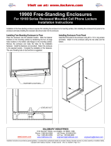
Constructing Concrete Base
Prepare a concrete pad at least 4 feet square (for one (1) pedestal
parcel locker) by a minimum 8 inches depth on a compacted gravel
or crushed stone fill reaching down to the maximum frost depth. The
concrete pad should include steel reinforcing rods and four (4) 1/2”-
13 anchor bolts protruding at least 1 inch above the concrete surface.
Place the anchor bolts in a 4 inch by 10 inch pattern matching the
pedestal base as shown in the illustration.
Installing Pedestal on Concrete Base
When the concrete has cured sufficiently, set the pedestal on the
concrete base with the ends of the four anchor bolts protruding
through the holes in the pedestal base plate. Install the nuts and
washers on the anchor bolts and tighten securely. If necessary, use
shims or the extra nuts provided to level the pedestal.
Installing Parcel Locker Unit on Pedestal
Open the lower door of the pedestal parcel locker and slide out the
floating bottom shelf, exposing the four (4) holes to attach the unit to
the top of the pedestal. Lift the unit onto the top of the pedestal,
aligning the holes, and install the four (4) 3/8”-16 carriage bolts
upward from underneath the pedestal top plate. From inside the
parcel compartment, install the four (4) lock washers and nuts onto
the bolt threads. Torque the nuts to 22 foot-pounds. Reinstall the
floating shelf, covering the attachment holes.
Model 3302 Outdoor Parcel Locker (Includes Pedestal)
SALSBURY INDUSTRIES
1010 East 62
nd
Street, Los Angeles, CA 90001-1598
Phone: 1-800-624-5269 Int’l Phone: 323-846-6700
Fax: 1-800-624-5299 Int’l Fax: 323-846-6800
Installation instructions are provided as general guidelines. It is advised that a professional installer be consulted. Salsbury Industries assumes no product assembly or installation liability.
Copyright © 2010 Salsbury Industries. All rights reserved. (Rev. 07, 7/22/2010)

Outdoor Parcel Locker – 3302
Installation of Arrow Lock
This document covers the installation of the Arrow Lock in the carrier access door. This lock is available only through the USPS and is to be
installed by authorized USPS personnel only.
Installation Procedure
1. Open carrier access door. See Illustration 1.
2. Remove five (5) 10-32 lock nuts with lock support plate. Dispose
of plastic shipping spacer. Use 3/8” socket wrench for lock nuts.
See Illustration 2.
3. Place Arrow Lock in one (1) Arrow Lock security bracket and
position on door. See Illustration 3.
4. Replace one (1) 10-32 lock nut in the rear position to secure the
Arrow Lock security bracket.
5. Install lock support plate as shown.
6. Replace four (4) 10-32 lock nuts. Torque to 25 to 30 inch-pounds.
Overtightening may keep Arrow Lock from operating correctly.
Illustration 1
Illustration 2
Illustration 3
SALSBURY INDUSTRIES
1010 East 62
nd
Street, Los Angeles, CA 90001-1598
Phone: 1-800-624-5269 Int’l Phone: 323-846-6700
Fax: 1-800-624-5299 Int’l Fax: 323-846-6800
Installation instructions are provided as general guidelines. It is advised that a professional installer be consulted. Salsbury Industries assumes no product assembly or installation liability.
Copyright © 2010 Salsbury Industries. All rights reserved. (Rev. 07, 7/22/2010)
/