Draper Access M Operating instructions

Category
Projection screens
Type
Operating instructions

Draper Access M is a manually-operated ceiling-recessed projection screen designed for precise and safe installation in various indoor settings. Its key features include:

  • Manually operated: Allows for controlled and smooth screen movement without the need for electrical power.

  • Ceiling-recessed design: Provides a discreet and integrated installation, blending seamlessly into the ceiling for a clean and professional look.

  • Projection screen: Offers a suitable surface for displaying presentations, videos, and other visual content in a variety of spaces such as classrooms, conference rooms, and home theaters.

21
PERSONNEL REQUIRED
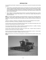
Overview - Components
CAUTION
Read and understand
all warnings
(below)
before beginning
installation.
Dowel
Mounting
Bracket
Leveling
Brackets
Hoisting
Bracket
Mounting
Bracket
Hoisting
Bracket
Trim
Flange
VIEWING SURFACE
TOOLS REQUIRED
PLEASE READ - Safety Information
WARNING
Improper installation and use of the Access M screen can result in serious injury or death. Primarily, injuries can occur if the unit falls due to imprecise
installation, mishandling of the unit during installation, or installation on an insufficient wall or ceiling structure. Please use extreme care.
1. Please read the following installation guidelines thoroughly and follow them carefully.
Failure to do so may cause product to fall or otherwise fail, and could result in serious injury.
2. Installation and calibration of the unit should only be performed by an authorized, qualified,
and experienced professional.
3. Do not afx the unit to walls or ceilings that have inadequate strength to permanently hold
the unit during use. It is the owner’s and installer’s responsibility to confirm the wall or
ceiling to which the unit attaches is sufficient to permanently hold the weight and stress
loads of the unit at all times. Draper®, Inc., is not responsible for improper installation,
application, testing, or workmanship related to the product at place of installation.
4. It is the installer’s responsibility to make sure appropriate fasteners are used for mounting.
5. All hardware must be installed level. Unit must be level and square.
6. Never leave the area while operating the unit during installation, maintenance, or normal
operation, unless it is secure and safe.
7. Before testing or operation, carefully inspect the entire area and path
(especially
underneath)
of unit to be sure no persons or objects are in the area.
8. During testing or operation, carefully watch the surrounding area for any potential safety
concerns including nearby persons or objects.
9. After installation, the entire system, including all sensors, should be carefully tested to
ensure safe and normal operation. Extreme care should be taken during testing to remain
clear of moving parts to avoid possible injury.
10. Operation of unit should be performed only by authorized and qualified personnel, who have
been trained in its safe and effective operation and understand its safety features.
11. The safety features of the unit should never be disabled, bypassed, or overridden. The
system should not be operated until all safety features are properly and completely
installed, calibrated, and tested.
12. Unit may need to comply with local, state, or district rules and regulations, in particular
when installed in schools. All applicable rules and regulations should be reviewed before
installation and use.
13. Failure to precisely follow installation guidelines invalidates all warranties.
14. Custom products/installations may not be reflected in this manual. Call Draper, Inc., if
you have questions about the installation of custom products or any questions about your
installation.
Before Beginning Installation
1.
Look for any job site conditions that could interfere with installation or operation of
the system.
2.
Read carefully and be sure to understand all installation instructions and all
related operations manuals. These instructions are intended to serve as a guide
for the installer and owner. They should be followed closely and combined with the
expertise of experienced qualified installers. Draper, Inc., is not responsible for
improper installation, application, testing, or workmanship related to the product at
place of installation. Please retain all instructions for future use.
3.
Open cartons lengthwise.
4.
Locate and lay out all pieces.
5.
Inspect all boxes to make sure you have received the proper unit and parts.
Controls may be shipped separately, or in same carton as unit.
6.
If you have any difficulties with installing, servicing, or operating your unit, call your
dealer or Draper, Inc., 765-987-7999.
Important Safety Information Important Safety Information
POWER DRILL
PENCIL
TAPE MEASURE
HARDWARE
(by others)
LEVEL
Draper, Inc. | 411 S. Pearl St. Spiceland, IN 47385
draperinc.com | 765.987.7999 | 800.238.7999
© 2021 All Rights Reserved | FORM: AccessM_Inst21
Access M
Manually-operated ceiling-recessed projection screen
INSTRUCTIONS
INSTALLATION & OPERATION
If you have any difficulties installing or servicing your
Access screen, call your dealer or Draper, Inc.
CENTER of CASE
BOTTOM ACCESS
PANEL DOOR
BOTTOM FLANGE OF ACCESS HOUSING
HOUSING
Section 2 - Bottom Access Panel Installation/Removal
BOTTOM ACCESS PANEL DOOR
BOTTOM FLANGE OF ACCESS HOUSING
CAUTION:
Beware of
pinch points at
ends of closure.
Section 1 - Hanging Screen
Please Note: The following steps only apply when
changing or installing the roller. Product ships with Roller
and fabric already in place.
Please Note: When locating viewing surface and checking
clearance for screen operation, ensure that surface is
centered in the case.
HOISTING
BRACKET
CASE
MOUNTING
BRACKET
CASE
MOUNTING
BRACKETS
ALTERNATE
INSTALLATION
Additional set of brackets
required, but NOT included.
TYPICAL
INSTALLATION
With typical installation, brackets
may be angled to meet installation requirements.
2. Access panel
will hinge down.
1. Remove screws
from both ends
of Housing.
1.
Engage each case mounting bracket
(attached to case)
with top of housing and tighten set screws.
2.
Screen should be sufciently supported to withstand
vibration.
Please Note: A hoisting bracket is included on each end of
the case to aid in overhead installation.
3.
Ensure that fasteners are of adequate strength and
suitable for the mounting surface chosen. Supporting
hardware such as chains, cables, two
3/8
"
(9.5 mm)
rods,
etc., must be precisely vertical.
4.
Entire bottom of case must be readily accessible after
installation is complete.
5.
Front, back, and top of case must be straight—not
forced to warp or bow.
CAUTION: Screen case and flange are not designed to
serve as ceiling support.
6.
Do not seal unit in ceiling until screen operates
successfully.
Please Note: If case is painted on location, removal of
roller/fabric assembly is recommended prior to painting.
If not removed, slot on bottom of case should be shielded
to protect viewing surface from paint splatters/overspray.
Bottom access panel secures to the
screen housing with two screws
(one
on each end)
, and is held in the closed
position by engagement brackets with
ball detents that snap into case support
brackets.
1. Attaching Brackets:
Insert pin in top slot
and push up.
3. Bracket With Ball Detent:
Engages with Access Panel
Support Bracket.
2. Rotate bracket
clockwise to lock
bracket in place.
Access Panel Support Bracket
Please Note: There are 2 pins and
the slots are 9, which requires
the bracket to be inserted, then
rotated slightly
page 2 of 4
Access M
Section 3 - Spring Roller/Fabric Installation
Operating Instructions—Standard
To lower screen: Grasp center of slat, or pull ring, and pull down. Hesitate, then allow screen to
retract very slowly until it locks in place.
To raise screen: Grasp center of slat, or pull cord, pull screen down and, while holding, allow for
retraction into desired position to reduce risk of injury from falling screen.
Caution: Do not allow screen roller to become exposed by pulling picture surface too far down.
Operating Instructions—AutoReturn
To lower screen:
Pull screen down. Hesitate—then allow screen
to retract very slowly until it locks in place.
To raise screen:
Pull screen down gently, then release.
STANDARD OPERATOR AUTORETURN OPERATOR
pin into nylon bushing on idler bracket.
9.
Roller idler pin goes through idler bracket. Reinstall washer.
10.
Install the retaining clip on the spear, locking spear and bracket together.
Caution: Failure to replace washer and retaining clip could result in
separation of roller from brackets.
11.
Center roller/fabric assembly by sliding mounting brackets left or right.
12.
Securely tighten set screws on the idler end mounting bracket
13.
Attach door support brackets.
14.
Reinstall bottom access panel as previously described.
1.
Remove bottom access panel.
2.
Back out the set screws in bracket until flush with top side of the bracket.
3.
The spear end mounting bracket has rectangular openings
(C, at right)
for
accepting roller spear. To engage operator end bracket flange
(above the
two channels in the top of the screen housing)
, rotate bracket approximately 45°
counterclockwise to allow top surface of operator bracket to rest flat against
top inside housing.
Please Note: Install the roller level using the corresponding "C" spring operator slot.
4.
Rotating the bracket clockwise until it engages in the channel, slide it along
the length of the housing toward the left end, leaving approximately
¾
"
(19mm)
clearance between bracket and endcap.
5.
Tighten the set screws on the bracket flange using
1/8
"
(3mm)
hex key.
6.
Engage the idler end bracket
(nylon bushing)
in the same manner as the spear end
bracket and slide toward opposite end of screen housing. Do not tighten the set
screws on this bracket until the roller/fabric assembly is installed.
Caution: Step 7 requires two people to perform safely.
7.
Locate the roller/fabric assembly and remove the retaining clip and flat washer
from the idler end pin, and remove retaining clip from the spear. Remove
brackets from roller. Lift roller/fabric assembly into screen housing and engage
the spear of the roller completely into the spear mounting bracket.
For Auto Return ONLY:
• 1
¾
"
(44mm)
diameter roller: Arrow imprinted on the spring end of the roller
must point UP. Use the slot closest to the edge of the bracket.
2
¼
"
(57mm)
or 3"
(76mm)
diameter roller: Notch cut out on the spring end
of the roller must point DOWN. Use the appropriate slot.
8.
Support idler end of roller and slide mounting bracket toward roller. Insert roller
Retaining
Clip
BRACKET
ROLLER PIN
RETAINING
CLIP
WASHER
NYLON BUSHING
ROLLER
BRACKET
BRACKET
Retaining
Clip
BRACKET
B
A
C
{
C.
Spring Roller operator
B.
Automatic Return operator
A.
Standard operator
page 3 of 4
Access M
Section 5 - Case Length Dimensions
Section 6 - Case Width Dimensions Section 7 - Mounting Bracket Dimensions
For minimum length of ceiling cutout: subtract 1
¼
"
(32mm)
from case length
(measured from outer edge of flanges)
.
For minimum width of cutout
(front to back)
: see case width dimensions below.
** Leveling bracket is used to level the case and should NOT be used to support the weight of the unit.
The leveling bracket is screwed to the side of the case. Hardware used for leveling provided by others.
There are several knock-outs in the screen housing to allow the Leveling Bracket to be adjusted laterally up to 16"
(40.6cm)
in either direction.
2
"
(57mm)
2
"
(57mm)
HOISTING
BRACKET HOISTING
BRACKET
ACCESS M
18
"
(457mm)
18
"
(457mm)
8"
(203mm)
"
(19mm)
6

"
(175mm)
"
(19mm)
1

" TYP
(35mm)

"
(22mm)
LEVELING BRACKET**
CASE LENGTH
"
(19mm)
7

"
(187mm)

"
(16mm)
"
(13mm)
6
"
(165mm)
8

"
(205mm)
6

"
(173mm)

"
(11mm)
9

"
(232mm)

"
(22mm)

"
(16mm)
Center
of Case
2
"
(57mm)
2
"
(57mm)
HOISTING
BRACKET HOISTING
BRACKET
ACCESS M
18"
(457mm)
18"
(457mm)
8"
(203mm)
"
(19mm)
6

"
(175mm)
"
(19mm)
1

" TYP
(35mm)

"
(22mm)
LEVELING BRACKET**
CASE LENGTH
"
(19mm)
7

"
(187mm)

"
(16mm)
"
(13mm)
6
"
(165mm)
8

"
(205mm)
6

"
(173mm)

"
(11mm)
9

"
(232mm)

"
(22mm)

"
(16mm)
Center
of Case
"
(11mm)
1"
(35mm)
9 "
(232mm)
7"
(200mm)
3 "
(86mm)
page 4 of 4
Access M
  • Page 1 1
  • Page 2 2
  • Page 3 3
  • Page 4 4

Draper Access M Operating instructions

Category
Projection screens
Type
Operating instructions

Draper Access M is a manually-operated ceiling-recessed projection screen designed for precise and safe installation in various indoor settings. Its key features include:

  • Manually operated: Allows for controlled and smooth screen movement without the need for electrical power.

  • Ceiling-recessed design: Provides a discreet and integrated installation, blending seamlessly into the ceiling for a clean and professional look.

  • Projection screen: Offers a suitable surface for displaying presentations, videos, and other visual content in a variety of spaces such as classrooms, conference rooms, and home theaters.

Ask a question and I''ll find the answer in the document

Finding information in a document is now easier with AI