Page is loading ...

D1 Series and FM100
Draper Header and Float Module for
Combines
Operator’s Manual
215181 Revision A
Original Instruction
The Harvesting Specialists.

D1 Series Draper Header for Combines and FM100 Float Module
1031757
Published February 2020.
© 2020 MacDon Industries, Ltd.
The information in this publication is based on the information available and in effect at the time of printing. MacDon
Industries, Ltd. makes no representation or warranty of any kind, whether expressed or implied, with respect to the
information in this publication. MacDon Industries, Ltd. reserves the right to make changes at any time without notice.

Declaration of Conformity
1032113
215181 i Revision A

1032114
215181 ii Revision A

1029505
215181 iii Revision A

1026044
215181 iv Revision A

Introduction
This instructional manual contains information on the D1 Series Draper Header and the FM100 Float Module. It must be
used in conjunction with the combine operator's manual. The FM100 Float Module is used to attach a D1 Series Draper
Header to a combine.
The D1 Series Draper Header is specially designed as a straight cut header and is equipped to work well in all straight cut
conditions—whether cutting on or above the ground.
Carefully read all the material provided before attempting to use the machine.
Use this manual as your first source of information about the machine. If you follow the instructions provided, your header
will work well for many years.
MacDon provides warranty for Customers who operate and maintain their equipment as described in this manual. A copy
of the MacDon Industries Limited Warranty Policy, which explains this warranty, should have been provided to you by your
Dealer. Damage resulting from any of the following conditions will void the warranty:
• Accident
• Misuse
• Abuse
• Improper maintenance or neglect
• Abnormal or extraordinary use of the machine
• Failure to use the machine, equipment, component, or part in accordance with the manufacturer’s instructions
The following conventions are used in this document:
• Right and left are determined from the operator’s position. The front of the header faces the crop; the back of the
header attaches to the float module and combine.
• Unless otherwise noted, use the standard torque values provided in Chapter 8.1 Torque Specifications, page 653.
When setting up the machine or making adjustments, review and follow the recommended machine settings in all relevant
MacDon publications. Failure to do so may compromise machine function and machine life and may result in a hazardous
situation.
The Table of Contents and Index will guide you to specific areas of this manual. Study the Table of Contents to familiarize
yourself with how the information is organized.
1024245
A
Manual Storage Location
Keep this manual handy for frequent reference and to pass on
to new Operators or Owners. A manual storage case (A) is
located inside the header left endshield.
Call your MacDon Dealer if you need assistance, information, or
additional copies of this manual.
NOTE:
Keep your MacDon publications up-to-date. The most current
version can be downloaded from our website
(www.macdon.com) or from our Dealer-only site
(https://portal.macdon.com) (login required).
This document is available in English, French, Portuguese, and
Russian.
215181 v Revision A

Summary of Changes
At MacDon, we’re continuously making improvements; occasionally these improvements affect product documentation.
The following list provides an account of major changes from the previous version of this document.
Section
Summary of Change
Internal Use
Only
1.7 Safety Decal Locations, page 8 Updated decal illustration for FM100.
ECN 58655
1.7 Safety Decal Locations, page 8 Added D115 information.
Tech Pubs
1.8 Understanding Safety Signs, page 17 Updated illustration for decal MD #113482.
Tech Pubs
1.8 Understanding Safety Signs, page 17 Added new decal (MD #304865) for model year 2020.
ECN 58722
2.2 Specifications, page 25 Added D115 information to topic tables.
Engineering
2.3.2 FM100 Float Module, page 30 Updated illustrations. Tech Pubs
3.8.1 FM100 Feed Auger Configurations,
page 62
Added Ultra Wide auger flighting configuration to topic.
Engineering,
Tech Pubs
Converting from Medium Configuration to
Wide Configuration or Ultra Wide
Configuration, page 76
Added content per Ultra Wide flighting configuration
Engineering,
Tech Pubs
Converting from Ultra Narrow or Narrow
Configuration to Wide or Ultra Wide
Configuration, page 78
Added content per Ultra Wide flighting configuration
Engineering,
Tech Pubs
Converting from Wide Configuration to
Ultra Wide Configuration, page 80
Added content per Ultra Wide flighting configuration
Engineering,
Tech Pubs
3.8.1 FM100 Feed Auger Configurations,
page 62
Added CLAAS 8000 to list of compatible combines for
wide auger flighting configuration.
Engineering
3.8.1 FM100 Feed Auger Configurations,
page 62
Added AGCO IDEAL
™
Series to list of compatible combines
for narrow auger flighting configuration.
ECN 59301
Adjusting Header Angle from Combine,
page 103
Added IMPORTANT note to topic.
Engineering
Checking and Adjusting Reel Height
Sensor, page 118
Updated reel height sensor voltage limits table to include
AGCO IDEAL
™
Series information.
ECN 58283
Repositioning Fore-Aft Cylinders on Single
Reel, page 124
Updated illustrations for clarity.
Tech Pubs
Repositioning Fore-Aft Cylinders on
Double Reel, page 126
Updated illustrations for clarity.
Tech Pubs
3.9.2 Troubleshooting Auto Header Height
/ Float Indicator, page 150
Added new topic.
Tech Pubs,
Product
Support
3.9.4 AGCO IDEAL
™
Series Combines, page
163
Added new topic.
Engineering
Setting up the Header – AGCO IDEAL
™
Series, page 163
Added new topic.
Engineering
Setting Minimum Reel Speed and
Calibrating Reel – AGCO IDEAL
™
Series,
page 168
Added new topic.
Engineering
215181 vi Revision A

Section
Summary of Change
Internal Use
Only
Setting up Automatic Header Controls –
AGCO IDEAL
™
Series, page 170
Added new topic.
Engineering
Calibrating the Header – AGCO
IDEAL
™
Series, page 171
Added new topic.
Engineering
Operating the Header – AGCO IDEAL
™
Series, page 174
Added new topic.
Engineering
Reviewing Header In-Field Settings –
AGCO IDEAL
™
Series, page 176
Added new topic.
Engineering
3.9.11 CLAAS 8000/7000 Series Combines,
page 236
Added new topic.
Engineering
Setting up the Header – CLAAS 8000/7000
Series, page 236
Added new topic.
Engineering
Calibrating the Auto Header Height
Control – CLAAS 8000/7000 Series, page
238
Added new topic.
Engineering
Setting Cut and Reel Height Preset –
CLAAS 8000/7000 Series, page 241
Added new topic.
Engineering
Setting the Sensitivity of the Auto Header
Height Control – CLAAS 8000/7000 Series,
page 242
Added new topic.
Engineering
Adjusting Auto Reel Speed – CLAAS 8000/
7000 Series, page 244
Added new topic.
Engineering
Calibrating Reel Height Sensor – CLAAS
8000/7000 Series, page 245
Added new topic.
Engineering
4.1.2 Using Stripper Bars, page 371
Removed irrelevant statement about cereal crops.
Engineering
4.4 AGCO IDEAL
™
Series Combines, page
388
Added new topic.
Engineering
4.4.1 Attaching Header to an AGCO
IDEAL
™
Series Combine, page 388
Added new topic.
ECN 57194
4.4.2 Detaching Header from an AGCO
IDEAL
™
Series Combine, page 391
Added new topic.
ECN 57194
4.6.1 Attaching Header to CLAAS
Combine, page 401
Updated illustration for clarity. Tech Pubs
5.3.1 Maintenance Schedule/Record, page
432
Updated maintenance schedule/record to include task for
checking link holder hooks as part of regular machine
inspection and maintenance.
Product
Support
5.4.2 Adding Oil to Hydraulic Reservoir,
page 455
Updated illustration. Tech Pubs
5.4.3 Changing Oil in Hydraulic Reservoir,
page 455
Updated procedure steps and illustrations.
ECN 57856
5.4.3 Changing Oil in Hydraulic Reservoir,
page 455
Updated oil amount from 75 liters (20 gallons) to 80 liters
(22.5 gallons).
Engineering
215181 vii Revision A

Section
Summary of Change
Internal Use
Only
5.7.3 Adjusting Auger Drive Chain Tension,
page 470
Updated procedure step to include precise deflection
measurement and to include AGCO IDEAL
™
Series
information in table.
Engineering
Installing Split Finger Holder, page 480
Added step for inspecting finger prior to installation.
Engineering
5.10.7 Checking Link Holder Hooks, page
545
Added new topic.
Product
Support
6.5.5 Draper Clips, page 638
Updated option information (name, cleat specifics per
draper part number).
ECN 58960
Inside back cover
Updated hydraulic oil specification with detailed
descriptions of generic as well as name brand products.
Engineering,
Tech Pubs
215181 viii Revision A

Model and Serial Number
Record the model number, serial number, and model year of the header, combine float module, and transport / stabilizer
wheel option (if installed) in the spaces provided.
NOTE:
Right and left designations are determined from the operator’s position, facing forward.
1020884
A
Figure 1: Header Serial Number Plate Location
D1 Series Draper Header
Header Model:
Serial Number:
Year:
Header serial number plate (A) is located on the upper corner
on the left endsheet.
1029556
A
Figure 2: Float Module Serial Number Plate Location
FM100 Float Module for Combine
Serial Number:
Year:
Float module serial number plate (A) is located on the top left
of the float module frame.
1005072
A
Figure 3: Slow Speed Transport / Stabilizer Wheel
Slow Speed Transport / Stabilizer Wheel Option
Serial Number:
Year:
Transport serial number plate (A) is located on the right axle
assembly.
215181 ix Revision A


215181 xi Revision A
Declaration of Conformity .. ............................................................................................................................i
Introduction ...............................................................................................................................................v
Summary of Changes................................................................................................................................... vi
Model and Serial Number ............................................................................................................................ ix
Chapter 1: Safety ............................................................................................................... ......................... 1
1.1 Safety Alert Symbols ............................................................................................................................... 1
1.2 Signal Words ......................................................................................................................................... 2
1.3 General Safety ....................................................................................................................................... 3
1.4 Maintenance Safety ................................................................................................................................ 5
1.5 Hydraulic Safety .....................................................................................................................................6
1.6 Safety Signs ........................................................................................................................................... 7
1.6.1 Installing Safety Decals....................................................................................................................7
1.7 Safety Decal Locations............................................................................................................................. 8
1.8 Understanding Safety Signs .................................................................................................................... 17
Chapter 2: Product Overview........................ .............................................................................. ............. 23
2.1 Definitions .......................................................................................................................................... 23
2.2 Specifications....................................................................................................................................... 25
2.3 Component Identification ...................................................................................................................... 29
2.3.1 D1 Series Draper Header for Combines ............................................................................................ 29
2.3.2 FM100 Float Module .................................................................................................................... 30
Chapter 3: Operation................................................................. ............................................................... 33
3.1 Owner/Operator Responsibilities ............................................................................................................ 33
3.2 Operational Safety................................................................................................................................ 34
3.2.1 Header Safety Props ..................................................................................................................... 34
3.2.2 Reel Safety Props ......................................................................................................................... 35
Engaging Reel Safety Props........................................................................................................... 35
Disengaging Reel Safety Props ...................................................................................................... 36
3.2.3 Header Endshields ....................................................................................................................... 37
Opening Endshields..................................................................................................................... 37
Closing Endshields ...................................................................................................................... 38
Removing Endshields...................................................................................................................38
Installing Endshields .................................................................................................................... 39
Checking and Adjusting Endshields ................................................................................................ 40
3.3 Daily Start-Up Check ............................................................................................................................. 42
3.4 Break-in Period .................................................................................................................................... 43
3.5 Shutting down the Combine ................................................................................................................... 44
3.6 Cab Controls ........................................................................................................................................ 45
3.7 Header Setup....................................................................................................................................... 46
3.7.1 Header Attachments..................................................................................................................... 46
3.7.2 Header Settings ........................................................................................................................... 46
3.7.3 Optimizing Header for Straight Combining Canola.............................................................................. 57
TABLE OF CONTENTS

215181 xii Revision A
Checking and Adjusting Feed Auger Springs..................................................................................... 58
3.7.4 Reel Settings ............................................................................................................................... 59
3.8 Header Operating Variables.................................................................................................................... 61
3.8.1 FM100 Feed Auger Configurations .................................................................................................. 62
Converting from Ultra Narrow Configuration or Narrow Configuration to Medium Configuration.............. 67
Converting from Wide Configuration to Medium Configuration .......................................................... 70
Converting from Medium Configuration or Wide Configuration to Narrow Configuration ........................ 72
Converting from Ultra Narrow Configuration to Narrow Configuration ................................................. 75
Converting from Medium Configuration to Wide Configuration or Ultra Wide Configuration.................... 76
Converting from Ultra Narrow or Narrow Configuration to Wide or Ultra Wide Configuration .................. 78
Converting from Wide Configuration to Ultra Wide Configuration ....................................................... 80
Converting from Medium Configuration or Wide Configuration to Ultra Narrow Configuration................. 81
Converting from Narrow Configuration to Ultra Narrow Configuration ................................................. 85
3.8.2 Cutting Height ............................................................................................................................. 87
Cutting off the Ground ................................................................................................................ 87
Cutting on the Ground................................................................................................................. 92
3.8.3 Header Float ............................................................................................................................... 94
Checking and Adjusting Header Float ............................................................................................. 95
Locking/Unlocking Header Float .................................................................................................. 100
3.8.4 Header Angle ............................................................................................................................ 101
Adjusting Header Angle from Combine ......................................................................................... 103
3.8.5 Reel Speed................................................................................................................................ 109
Optional Reel Drive Sprockets ..................................................................................................... 110
3.8.6 Ground Speed ........................................................................................................................... 111
3.8.7 Draper Speed ............................................................................................................................ 112
Adjusting Side Draper Speed....................................................................................................... 112
Feed Draper Speed ................................................................................................................... 114
3.8.8 Knife Speed Information.............................................................................................................. 114
Checking Knife Speed ................................................................................................................ 116
3.8.9 Reel Height ............................................................................................................................... 117
Checking and Adjusting Reel Height Sensor ................................................................................... 118
Replacing Reel Height Sensor...................................................................................................... 121
3.8.10 Reel Fore-Aft Position ............................................................................................................... 123
Adjusting Reel Fore-Aft Position .................................................................................................. 123
Repositioning Fore-Aft Cylinders on Single Reel.............................................................................. 124
Repositioning Fore-Aft Cylinders on Double Reel ............................................................................ 126
Repositioning Fore-Aft Cylinders with Multi-Crop Rapid Reel Conversion Option.................................. 129
Repositioning Fore-Aft Cylinders on European-Configured Headers ................................................... 132
3.8.11 Reel Tine Pitch ......................................................................................................................... 136
Reel Cam Settings ..................................................................................................................... 136
Adjusting Reel Cam ................................................................................................................... 138
3.8.12 Crop Dividers........................................................................................................................... 139
Removing Crop Dividers with Latch Option from Header.................................................................. 139
Removing Crop Dividers without Latch Option from Header ............................................................. 140
Installing Crop Dividers with Latch Option onto Header ................................................................... 141
Installing Crop Dividers without Latch Option onto Header .............................................................. 143
3.8.13 Crop Divider Rods..................................................................................................................... 144
Removing Crop Divider Rods....................................................................................................... 144
Installing Crop Divider Rods ........................................................................................................ 145
Rice Divider Rods...................................................................................................................... 146
3.8.14 Setting Auger Position............................................................................................................... 146
TABLE OF CONTENTS

215181 xiii Revision A
3.9 Auto Header Height Control ................................................................................................................. 148
3.9.1 Sensor Operation ....................................................................................................................... 149
3.9.2 Troubleshooting Auto Header Height / Float Indicator ...................................................................... 150
3.9.3 Sensor Output Voltage Range – Combine Requirements ................................................................... 151
10 Volt Adapter (MD #B6421) – New Holland Combines Only ........................................................... 152
Manually Checking Voltage Range – One-Sensor System.................................................................. 153
Manually Checking Voltage Range – Two-Sensor System ................................................................. 155
Adjusting Voltage Limits – One-Sensor System ............................................................................... 159
Adjusting Voltage Limits – Two-Sensor System............................................................................... 160
3.9.4 AGCO IDEAL
™
Series Combines .................................................................................................... 163
Setting up the Header – AGCO IDEAL
™
Series ................................................................................ 163
Setting Minimum Reel Speed and Calibrating Reel – AGCO IDEAL
™
Series........................................... 168
Setting up Automatic Header Controls – AGCO IDEAL
™
Series .......................................................... 170
Calibrating the Header – AGCO IDEAL
™
Series ............................................................................... 171
Operating the Header – AGCO IDEAL
™
Series ................................................................................ 174
Reviewing Header In-Field Settings – AGCO IDEAL
™
Series ............................................................... 176
3.9.5 Case IH 5088/6088/7088 Combines............................................................................................... 177
Calibrating the Auto Header Height Control – Case IH 5088/6088/7088 ............................................. 177
Setting the Sensitivity of the Auto Header Height – Case IH 5088/6088/7088 ...................................... 179
3.9.6 Case IH 130 and 140 Series Mid-Range Combines ............................................................................ 180
Setting up the Header on the Combine Display – Case IH 5130/6130/7130; 5140/6140/7140................. 180
Checking Voltage Range from Combine Cab – Case IH 5130/6130/7130; 5140/6140/7140..................... 183
Calibrating Auto Header Height Control – Case IH 5130/6130/7130, 5140/6140/7140 .......................... 185
Setting Preset Cutting Height – Case 5130/6130/7130, 5140/6140/7140 ............................................ 186
3.9.7 Case IH 7010/8010, 120, 230, 240, and 250 Series Combines ............................................................. 189
Checking Voltage Range from the Combine Cab – Case IH 8010 ........................................................ 189
Setting Header Controls – Case IH 8010 ........................................................................................ 192
Checking Voltage Range from the Combine Cab – Case IH 7010/8010, 120, 230, 240, and 250 Series
Combines.................................................................................................................... 193
Calibrating the Auto Header Height Control – Case IH 7010/8010,120, 230, 240, and 250 Series
Combines.................................................................................................................... 196
Calibrating the Auto Header Height Control – Case IH Combines with Version 28.00 or Higher
Software..................................................................................................................... 199
Checking Reel Height Sensor Voltages – Case IH Combines .............................................................. 204
Setting Preset Cutting Height – Case IH 7010/8010, 120, 230, 240, and 250 Series Combines ................. 205
3.9.8 Challenger and Massey Ferguson 6 and 7 Series Combines................................................................ 207
Checking Voltage Range from the Combine Cab – Challenger and Massey Ferguson ............................. 207
Engaging the Auto Header Height Control – Challenger and Massey Ferguson ..................................... 209
Calibrating the Auto Header Height Control – Challenger and Massey Ferguson .................................. 210
Adjusting the Header Height – Challenger and Massey Ferguson....................................................... 212
Adjusting the Header Raise/Lower Rate – Challenger and Massey Ferguson ........................................ 213
Setting the Sensitivity of the Auto Header Height Control – Challenger and Massey Ferguson ................ 214
3.9.9 CLAAS 500 Series Combines ......................................................................................................... 215
Calibrating the Auto Header Height Control – CLAAS 500 Series ........................................................ 215
Setting Cutting Height – CLAAS 500 Series..................................................................................... 217
Setting the Sensitivity of the Auto Header Height Control –
CLAAS 500 Series ..................................... 219
Adjusting Auto Reel Speed – CLAAS 500 Series............................................................................... 222
3.9.10 CLAAS 600 and 700 Series Combines ........................................................................................... 225
Calibrating the Auto Header Height Control – CLAAS 600 and 700 Series ............................................ 225
Setting Cutting Height – CLAAS 600 and 700 Series ......................................................................... 228
Setting the Sensitivity of the Auto Header Height Control – CLAAS 600 and 700 Series.......................... 229
Adjusting Auto Reel Speed – CLAAS 600 and 700 Series................................................................... 231
TABLE OF CONTENTS

215181 xiv Revision A
Calibrating Reel Height Sensor – CLAAS 600 and 700 Series.............................................................. 232
Adjusting Auto Reel Height – CLAAS 600 and 700 Series .................................................................. 235
3.9.11 CLAAS 8000/7000 Series Combines.............................................................................................. 236
Setting up the Header – CLAAS 8000/7000 Series ........................................................................... 236
Calibrating the Auto Header Height Control – CLAAS 8000/7000 Series .............................................. 238
Setting Cut and Reel Height Preset – CLAAS 8000/7000 Series .......................................................... 241
Setting the Sensitivity of the Auto Header Height Control – CLAAS 8000/7000 Series............................ 242
Adjusting Auto Reel Speed – CLAAS 8000/7000 Series ..................................................................... 244
Calibrating Reel Height Sensor – CLAAS 8000/7000 Series................................................................ 245
3.9.12 Gleaner R65/R66/R75/R76 and S Series Combines ......................................................................... 248
Checking Voltage Range from the Combine Cab – Gleaner R65/R66/R75/R76 and Pre-2016
S Series....................................................................................................................... 248
Engaging the Auto Header Height Control – Gleaner R65/R66/R75/R76 and Pre-2016 S Series ............... 250
Calibrating the Auto Header Height Control – Gleaner R65/R66/R75/R76 and Pre-2016 S Series............. 252
Turning off the Accumulator – Gleaner R65/R66/R75/R76 and Pre-2016 S Series ................................. 254
Adjusting the Header Raise/Lower Rate – Gleaner R65/R66/R75/R76 and Pre-2016 S Series .................. 255
Adjusting Ground Pressure – Gleaner R65/R66/R75/R76 and Pre-2016 S Series ................................... 256
Adjusting the Sensitivity of the Auto Header Height Control – Gleaner R65/R66/R75/R76 and Pre-2016
S Series....................................................................................................................... 257
Troubleshooting Alarms and Diagnostic Faults – Gleaner R65/R66/R75/R76 and Pre-2016
S Series....................................................................................................................... 258
3.9.13 Gleaner S9 Series Combines ....................................................................................................... 260
Setting up the Header – Gleaner S9 Series .................................................................................... 260
Setting Minimum Reel Speed and Calibrating Reel – Gleaner S9 Series ............................................... 265
Setting up Automatic Header Controls – Gleaner S9 Series............................................................... 267
Calibrating the Header – Gleaner S9 Series.................................................................................... 269
Operating the Header – Gleaner S9 Series..................................................................................... 273
Reviewing Header In-Field Settings – Gleaner S9 Series ................................................................... 274
3.9.14 John Deere 60 Series Combines .................................................................................................. 275
Checking Voltage Range from the Combine Cab –
John Deere 60 Series ............................................. 275
Calibrating the Auto Header Height Control – John Deere 60 Series................................................... 277
Turning the Accumulator Off – John Deere 60 Series....................................................................... 279
Setting the Sensing Grain Header Height to 50 – John Deere 60 Series ............................................... 279
Setting the Sensitivity of the Auto Header Height Control – John Deere 60 Series ................................ 280
Adjusting the Threshold for the Drop Rate Valve – John Deere 60 Series ............................................ 281
3.9.15 John Deere 70 Series Combines .................................................................................................. 282
Checking Voltage Range from the Combine Cab – John Deere 70 Series ............................................. 282
Calibrating Feeder House Speed – John Deere 70 Series .................................................................. 285
Calibrating the Auto Header Height Control – John Deere 70 Series................................................... 285
Setting the Sensitivity of the Auto Header Height Control – John Deere 70 Series ................................ 287
Adjusting the Manual Header Raise/Lower Rate – John Deere 70 Series ............................................. 288
3.9.16 John Deere S and T Series Combines............................................................................................ 289
Checking Voltage Range from the Combine Cab – John Deere S and T Series....................................... 289
Calibrating the Auto Header Height Control – John Deere S and T Series ............................................ 292
Setting the Sensitivity of the Auto Header Height Control – John Deere S and T Series.......................... 295
Adjusting the Manual Header Raise/Lower Rate – John Deere S and T Series ...................................... 296
Setting Preset Cutting Height – John Deere S and T Series................................................................ 297
Calibrating Feeder House Fore-Aft Tilt Range – John Deere S and T Series .......................................... 300
Checking Reel Height Sensor Voltages – John Deere S and T Series .................................................... 303
Calibrating Reel Height Sensor – John Deere S and T Series .............................................................. 306
3.9.17 John Deere S7 Series Combines .................................................................................................. 308
Setting up Header – John Deere S7 Series ..................................................................................... 308
Checking Voltage Range from the Combine Cab – John Deere S7 Series ............................................. 312
TABLE OF CONTENTS

215181 xv Revision A
Calibrating Feeder House – John Deere S7 Series ........................................................................... 315
Calibrating Header – John Deere S7 Series .................................................................................... 317
3.9.18 New Holland Combines – CR/CX Series – 2014 and Prior ................................................................. 320
Checking Voltage Range from the Combine Cab – New Holland CR/CX Series ...................................... 320
Setting up Auto Header Height Control – New Holland CR/CX Series.................................................. 324
Calibrating the Auto Header Height Control – New Holland CR/CX Series............................................ 325
Calibrating Maximum Stubble Height – New Holland CR/CX Series .................................................... 327
Adjusting Header Raise Rate – New Holland CR/CX Series ................................................................ 328
Setting the Header Lower Rate – New Holland CR/CX Series............................................................. 329
Setting the Sensitivity of the Auto Header Height Control – New Holland CR/CX Series ......................... 330
Setting Preset Cutting Height – New Holland CR/CX Series ............................................................... 331
3.9.19 New Holland Combines – CR Series – 2015 and Later...................................................................... 332
Checking Voltage Range from the Combine Cab – New Holland CR Series ........................................... 332
Setting up Auto Header Height Control – New Holland CR Series....................................................... 335
Calibrating the Auto Header Height Control – New Holland CR Series ................................................ 339
Checking Reel Height Sensor Voltages – New Holland CR Series ........................................................ 342
Setting Preset Cutting Height – New Holland CR Series .................................................................... 343
Setting Maximum Work Height – New Holland CR Series ................................................................. 345
Configuring Reel Fore-Aft, Header Tilt, and Header Type – New Holland CR Series ............................... 346
3.10 Leveling the Header .......................................................................................................................... 348
3.11 Unplugging the Cutterbar ................................................................................................................... 350
3.12 Unplugging the FM100 ...................................................................................................................... 351
3.13 Upper Cross Auger ............................................................................................................................ 352
3.13.1 Removing Upper Cross Auger Flighting......................................................................................... 352
3.13.2 Installing Upper Cross Auger Flighting .......................................................................................... 353
3.14 Transporting the Header ................................................................................................................... 354
3.14.1 Transporting Header on Combine................................................................................................ 354
3.14.2 Towing ................................................................................................................................... 355
Attaching Header to Towing Vehicle ............................................................................................ 355
Towing the Header ................................................................................................................... 355
3.14.3 Converting from Transport to Field Position .................................................................................. 356
Removing Tow-Bar.................................................................................................................... 356
Storing the Tow-Bar .................................................................................................................. 357
Moving Front (Left) Wheels into Field Position............................................................................... 359
Moving Rear (Right) Wheels into Field Position .............................................................................. 360
3.14.4 Converting from Field to Transport Position .................................................................................. 362
Moving Front (Left) Wheels into Transport Position ........................................................................ 362
Moving Rear (Right) Wheels into Transport Position ....................................................................... 364
Attaching Tow-Bar .................................................................................................................... 367
3.15 Storing the Header............................................................................................................................ 370
Chapter 4: Header Attachment/Detachment........................................................................................ 371
4.1 FM100 Setup ..................................................................................................................................... 371
4.1.1 Using Auger Flighting .................................................................................................................. 371
4.1.2 Using Stripper Bars..................................................................................................................... 371
4.2 Case IH Combines............................................................................................................................... 372
4.2.1 Attaching Header to Case IH Combine ........................................................................................... 372
4.2.2 Detaching Header from Case IH Combine ....................................................................................... 377
TABLE OF CONTENTS

215181 xvi Revision A
4.3 AGCO (Challenger, Gleaner, and Massey Ferguson) Combines..................................................................... 380
4.3.1 Attaching Header to an AGCO (Challenger, Gleaner, or Massey Ferguson) Combine ............................... 380
4.3.2 Detaching Header from a Challenger, Gleaner, or Massey Ferguson Combine ....................................... 385
4.4 AGCO IDEAL
™
Series Combines ............................................................................................................. 388
4.4.1 Attaching Header to an AGCO IDEAL
™
Series Combine ..................................................................... 388
4.4.2 Detaching Header from an AGCO IDEAL
™
Series Combine ................................................................. 391
4.5 John Deere Combines.......................................................................................................................... 394
4.5.1 Attaching Header to John Deere Combine ...................................................................................... 394
4.5.2 Detaching Header from John Deere Combine.................................................................................. 398
4.6 CLAAS Combines ................................................................................................................................ 401
4.6.1 Attaching Header to CLAAS Combine ............................................................................................. 401
4.6.2 Detaching Header from CLAAS Combine ........................................................................................ 405
4.7 New Holland Combines ....................................................................................................................... 408
4.7.1 Attaching Header to New Holland CR/CX Combine........................................................................... 408
4.7.2 Detaching Header from New Holland CR/CX Combine ...................................................................... 412
4.7.3 CR Feeder Deflectors .................................................................................................................. 416
4.8 Attaching and Detaching Header to and from FM100 Float Module............................................................. 417
4.8.1 Attaching Header to FM100 Float Module ...................................................................................... 417
4.8.2 Detaching Header from FM100 Float Module.................................................................................. 423
Chapter 5: Maintenance and Servicing.................................................................................................. 429
5.1 Preparing Machine for Servicing............................................................................................................ 429
5.2 Maintenance Specifications .................................................................................................................. 430
5.2.1 Installing a Sealed Bearing ........................................................................................................... 430
5.3 Maintenance Requirements ................................................................................................................. 431
5.3.1 Maintenance Schedule/Record ..................................................................................................... 432
5.3.2 Break-In Inspection .................................................................................................................... 435
5.3.3 Preseason Servicing .................................................................................................................... 435
5.3.4 End-of-Season Service................................................................................................................. 436
5.3.5 Checking Hydraulic Hoses and Lines .............................................................................................. 437
5.3.6 Lubrication and Servicing............................................................................................................. 438
Service Intervals ....................................................................................................................... 438
Greasing Procedure................................................................................................................... 446
Lubricating Reel Drive Chain – Double Reel ................................................................................... 448
Lubricating Auger Drive Chain ..................................................................................................... 450
Lubricating Header Drive Gearbox ............................................................................................... 451
5.4 Hydraulics ......................................................................................................................................... 454
5.4.1 Checking Oil Level in Hydraulic Reservoir ....................................................................................... 454
5.4.2 Adding Oil to Hydraulic Reservoir.................................................................................................. 455
5.4.3 Changing Oil in Hydraulic Reservoir ............................................................................................... 455
5.4.4 Changing Oil Filter...................................................................................................................... 457
5.5 Electrical System ................................................................................................................................ 458
5.5.1 Replacing Light Bulbs .................................................................................................................. 458
5.6 Header Drive ..................................................................................................................................... 459
TABLE OF CONTENTS

215181 xvii Revision A
5.6.1 Removing Driveline .................................................................................................................... 459
5.6.2 Installing Driveline...................................................................................................................... 460
5.6.3 Removing Driveline Guard ........................................................................................................... 461
5.6.4 Installing Driveline Guard ............................................................................................................ 463
5.6.5 Adjusting Gearbox Drive Chain Tension.......................................................................................... 465
5.7 Auger ............................................................................................................................................... 466
5.7.1 Adjusting Auger to Pan Clearance ................................................................................................. 466
5.7.2 Checking Auger Drive Chain Tension.............................................................................................. 468
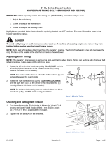
5.7.3 Adjusting Auger Drive Chain Tension ............................................................................................. 470
5.7.4 Installing Auger Drive Chain ......................................................................................................... 471
5.7.5 Auger Fingers ............................................................................................................................ 474
Removing Feed Auger Fingers ..................................................................................................... 474
Installing Feed Auger Fingers ...................................................................................................... 476
Replacing Broken Finger Holder................................................................................................... 479
Replacing Feed Auger Finger Guides ............................................................................................ 483
Checking Auger Finger Timing ..................................................................................................... 484
Adjusting Auger Finger Timing .................................................................................................... 485
Using Auger Flighting ................................................................................................................ 486
5.8 Knife ................................................................................................................................................ 487
5.8.1 Replacing Knife Section ............................................................................................................... 488
5.8.2 Removing Knife ......................................................................................................................... 489
5.8.3 Removing Knifehead Bearing........................................................................................................ 490
5.8.4 Installing Knifehead Bearing......................................................................................................... 490
5.8.5 Installing Knife........................................................................................................................... 491
5.8.6 Spare Knife ............................................................................................................................... 492
5.8.7 Knife Guards ............................................................................................................................. 493
Adjusting Pointed Knife Guards ................................................................................................... 493
Replacing Pointed Guards .......................................................................................................... 494
Replacing Stub Guards............................................................................................................... 495
Checking Knife Hold-Downs ........................................................................................................ 496
5.8.8 Knifehead Shield ........................................................................................................................ 499
Installing Knifehead Shield.......................................................................................................... 499
5.9 Knife Drive System.............................................................................................................................. 500
5.9.1 Knife Drive Box .......................................................................................................................... 500
Checking Knife Drive Box............................................................................................................ 500
Checking Mounting Bolts ........................................................................................................... 502
Removing Knife Drive Box .......................................................................................................... 502
Removing Knife Drive Box Pulley ................................................................................................. 505
Installing Knife Drive Box Pulley................................................................................................... 505
Installing Knife Drive Box............................................................................................................ 506
Changing Oil in Knife Drive Box ................................................................................................... 509
5.9.2 Knife Drive Belts ........................................................................................................................ 510
Non-Timed Knife Drive Belts ....................................................................................................... 510
Timed Double-Knife Drive Belts ................................................................................................... 514
5.10 Feed Draper..................................................................................................................................... 527
5.10.1 Replacing Feed Draper .............................................................................................................. 527
5.10.2 Checking and Adjusting Feed Draper Tension ................................................................................ 530
5.10.3 Feed Draper Drive Roller ........................................................................................................... 531
TABLE OF CONTENTS

215181 xviii Revision A
Removing Feed Draper Drive Roller ............................................................................................. 531
Installing Feed Draper Drive Roller............................................................................................... 533
Replacing Feed Draper Drive Roller Bearing................................................................................... 534
5.10.4 Feed Draper Idler Roller ............................................................................................................ 537
Removing Feed Draper Idler Roller .............................................................................................. 537
Replacing Feed Draper Idler Roller Bearing.................................................................................... 538
Installing Feed Draper Idler Roller................................................................................................ 541
5.10.5 Lowering FM100 Feed Deck Pan ................................................................................................. 542
5.10.6 Raising FM100 Feed Deck Pan .................................................................................................... 544
5.10.7 Checking Link Holder Hooks ....................................................................................................... 545
5.11 FM100 Stripper Bars and Feed Deflectors.............................................................................................. 547
5.11.1 Removing Stripper Bars ............................................................................................................. 547
5.11.2 Installing Stripper Bars .............................................................................................................. 548
5.11.3 Replacing Feed Deflectors on New Holland CR Combines ................................................................ 549
5.11.4 Replacing Feed Deflectors on Gleaner Combines............................................................................ 550
5.12 Header Side Drapers.......................................................................................................................... 554
5.12.1 Removing Side Drapers ............................................................................................................. 554
5.12.2 Installing Side Drapers............................................................................................................... 555
5.12.3 Adjusting Draper Tension........................................................................................................... 557
5.12.4 Adjusting Side Draper Tracking ................................................................................................... 559
5.12.5 Adjusting Deck Height ............................................................................................................... 560
5.12.6 Draper Roller Maintenance ........................................................................................................ 563
Inspecting Draper Roller Bearing ................................................................................................. 563
Draper Deck Idler Roller............................................................................................................. 563
Draper Deck Drive Roller............................................................................................................ 566
5.12.7 Draper Deflectors ..................................................................................................................... 571
Removing Narrow Draper Deflectors ............................................................................................ 571
Installing Narrow Draper Deflectors ............................................................................................. 572
5.13 Reel................................................................................................................................................ 573
5.13.1 Reel Clearance to Cutterbar ....................................................................................................... 573
Measuring Reel Clearance .......................................................................................................... 574
Adjusting Reel Clearance............................................................................................................ 576
5.13.2 Reel Frown.............................................................................................................................. 577
Adjusting Reel Frown................................................................................................................. 577
5.13.3 Centering the Reel.................................................................................................................... 578
Centering Reel on Double-Reel Header ......................................................................................... 578
Centering Reel on a Single-Reel Header ........................................................................................ 580
5.13.4 Reel Fingers............................................................................................................................. 581
Removing Steel Fingers.............................................................................................................. 581
Installing Steel Fingers ............................................................................................................... 582
Removing Plastic Fingers............................................................................................................ 583
Installing Plastic Fingers ............................................................................................................. 584
5.13.5 Tine Tube Bushings................................................................................................................... 585
Removing Bushings from Reels.................................................................................................... 585
Installing Bushings onto Reels ..................................................................................................... 591
5.13.6 Reel Endshields........................................................................................................................ 598
Replacing Reel Endshields .......................................................................................................... 598
Replacing Reel Endshield Supports............................................................................................... 600
TABLE OF CONTENTS
/