Reliance Controls PBN50 User guide
- Category
- Motorcycle Accessories
- Type
- User guide

POWER INLET BOX
CAT. NO. PBN50
50Amps, 120/240 VAC
INSTALLATION INSTRUCTIONS
IMPORTANT: Installation of this power inlet box and related wiring must be done by a qualified electrician
in compliance with all applicable electrical codes. When used to power a structure, this inlet must be used in
conjunction with a transfer switch. Not for indoor use. When using an engine driven generator, locate away
from doors and windows to avoid the build up of carbon monoxide from the engine exhaust in enclosed
areas.
INSTALLING A REMOTELY LOCATED POWER INLET BOX FOR SUPPLYING
POWER TO THE POWER INLET OF A TRANSFER SWITCH OR PANEL
Mount the power inlet box on the outside of the building in a convenient location, using the three holes
provided in the back of the cabinet. Using copper wire only and approved wiring methods run the wiring
through one of the knockouts in the cabinet to a junction box located near the transfer switch. REMOVE
KNOCKOUT FROM THE INSIDE OF THE ENCLOSURE USING A SCREWDRIVER INSERTED
INTO THE SLOT IN THE KNOCKOUT AND STRIKE GENTLY WITH A HAMMER. Install four
color-coded wires (AWG #8 minimum, AWG #6 maximum) -- use green for ground, white for neutral, and
two other distinguishing colors (typically black and red) for the 240V line. 3/4-inch fittings can be installed
directly into the knockout holes. To use 1/2-inch fittings, insert the knockout washer (provided) into the
open hole, and then install the fitting. Fittings should be torqued to not more than 120 in-lbs.
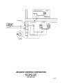
Strip the wire insulation 5/8" (do not tin conductors) and connect the wires in the power inlet box as follows
using a 5/32 Allen wrench making sure there is no wire insulation in any terminal and the inlet terminal
screws are tightened to 35 inch-pounds torque:
Hot wires to the brass terminals marked "X" and "Y".
Neutral wire to the nickel-plated neutral terminal marked "W".
Ground inlet wire to green screw terminal marked “G.”
PREPARING A CORD FROM THE GENERATOR TO THE POWER INLET BOX:
Using a 4-conductor 50 Amp portable cord suitable for the purpose, attach a male plug matching the
configuration of the generator outlet (typically Type CS-6364N) to one end, and a Type CS-6364N connector
(which will mate with the power inlet in the power inlet box) to the opposite end.
Following the wiring device manufacturer's instructions, wire the generator plug and the Type CS-6364N
connector as follows:
Red and black wires to the brass terminals marked "X" and "Y".
White wire to the nickel-plated neutral terminal marked "W".
Green wire to the green ground terminal marked "G".

RELIANCE CONTROLS CORPORATION
2001 YOUNG COURT
RACINE, WI 53404
800-634-6155
1/15/13
-
 1
1
-
 2
2


Reliance Controls PBN50 User guide
- Category
- Motorcycle Accessories
- Type
- User guide
Ask a question and I''ll find the answer in the document
Finding information in a document is now easier with AI
Related papers
Other documents
-
 Norweco 960G-500X 210P Installation guide
-
GE GFD65GSPNSN Installation guide
-
International comfort products N9MSE0401712A Installation guide
-
LG Electronics DLEY1901WE Installation guide
-
LG Electronics DLGX3901B Installation guide
-
Generac 6500E G0068651 User manual
-
-
-
Champion 100199 Installation guide
