Page is loading ...

Service Entrance Rated
Automatic Transfer Switches
Models:
KEP
Power Switching Devices:
Insulated-Case Circuit Breakers (ICCB)
Molded-Case Circuit Breakers (MCCB)
100--4000 Amperes
TP-6946 3/16b
Operation and
Installation

Product Identification Information
Product identification numbers determine service parts.
Record the product identification numbers in the spaces
below immediately after unpacking the products so that
the numbers are readily available for future reference.
Record field-installed kit numbers after installing the
kits.
Transfer Switch Identification Nu m bers
Record the product identification numbers from the
transfer switch nameplate.
Model Designation
Serial Number
Accessories
- Alarm Board
- Battery Module
- Controller Disconnect Switch
- Current Monitoring
- Digital Meter
- Heater
- I/O Module, Standard (max. 4) qty:
- I/O Module, High Power (max. 4) qty:
- Load Shed
- Line-Neutral Monitoring
- Seismic Certification
- Supervised Transfer Switch
- SurgeProtectionDevice(SPD)
-
-
-
-
-
-
Controller Identification
Record the controller description from the generator set
operation manual, spec sheet, or sales invoice.
Controller Description

TP-6946 3/16 3Table of Contents
Table of Contents
Safety Precautions and Instructions 5.........................................................
Introduction 7...............................................................................
List of Related Materials 7......................................................
Service Assistance 8.........................................................................
Section 1 Product Description 9..............................................................
1.1 General Description 9....................................................
1.2 Overcurrent Protection 10.................................................
1.3 Nameplate 10............................................................
1.4 Model Designation 11.....................................................
Section 2 Installation 13......................................................................
2.1 Introduction 13...........................................................
2.2 Receipt of Unit 13........................................................
2.2.1 Inspection 13....................................................
2.2.2 Lifting 13........................................................
2.2.3 Storage 14......................................................
2.2.4 Unpacking 14....................................................
2.3 Multi-Tap Voltage Capability 15.............................................
2.4 Set Overcurrent Protection 16..............................................
2.5 Installation 16............................................................
2.6 Seismic Certification 17...................................................
2.7 Manual Operation Check 18...............................................
2.7.1 Manual Operation Test Procedure, 100--1200A MCCB Models 18.......
2.7.2 Manual Operation Test Procedure, 800--4000 A ICCB Models 19.......
2.8 Controller Connections 20.................................................
2.8.1 Controller Input and Output Connections 21..........................
2.8.2 Harness Connection 21...........................................
2.8.3 Controller Ground 21..............................................
2.9 Electrical Wiring 22.......................................................
2.9.1 Source and Load Connections 22...................................
2.9.2 Engine Start Connection 24........................................
2.9.3 Position-Indicating Contacts 25.....................................
2.10 Communication and Accessory Connections 26..............................
2.11 Functional Tests 26.......................................................
Section 3 Three-Source Systems 27...........................................................
3.1 Three-Source Systems 27.................................................
3.2 Three Source Engine Start Mode 27........................................
3.2.1 Mode 1 27.......................................................
3.2.2 Mode 2 27.......................................................
3.3 Preferred Source Toggle 27................................................
3.4 Three Source System Test and Exercise 27..................................
3.4.1 Unloaded Test 27.................................................
3.4.2 Loaded Test 27...................................................
3.4.3 Unloaded Exercise 27.............................................
3.4.4 Loaded Exercise 27...............................................
3.5 Three-Source System Connection 28.......................................
3.6 ATS1 and ATS2 System Setup 30..........................................
Section 4 Communication and Accessory Connections 31
......................................
4.1 Introduction 31...........................................................
4.2 Communication Connections 31............................................
4.2.1 USB Port SiteTech Connection 31..................................
4.2.2 Modbus Connection 31............................................
4.2.3 Ethernet Connection 33...........................................

TP-6946 3/164 Table of Contents
4.3 Accessory Modules (Option Boards) 35.....................................
4.3.1 Accessory Module Mounting 35....................................
4.3.2 Input/Output (I/O) Modules 36......................................
4.3.3 External Battery Supply Module (EBSM/BOB) 37.....................
4.3.4 Alarm Module 38.................................................
4.4 Heater 40...............................................................
4.5 Other Accessories 41.....................................................
Section 5 Functional Tests 43.................................................................
5.1 Introduction 43...........................................................
5.2 Manual Operation Test 43.................................................
5.3 Ground Fault Site Test Requirements 43.....................................
5.4 Performance Test 43......................................................
5.5 Voltage Check 44.........................................................
5.6 Lamp Test 45............................................................
5.7 Automatic Operation Test 45...............................................
5.8 System Setup 45.........................................................
5.9 Exerciser Setup 45.......................................................
5.10 User Interface Cover 45...................................................
5.11 Startup Notification 45.....................................................
Section 6 Operation 47........................................................................
6.1 Transfer Switch Operation 47..............................................
6.1.1 Normal Operation 47..............................................
6.1.2 Overcurrent Trip 47...............................................
6.2 Service Disconnect Position 47.............................................
6.2.1 Service Disconnect to Emergency 47...............................
6.2.2 Service Disconnect to OFF 47......................................
6.2.3 Transformer Assemblies 49........................................
6.3 Service Disconnect to Emergency Operation 49..............................
6.3.1 Service Disconnect Procedure, Service Disconnect to Emergency 51...
6.3.2 Service Reconnect Procedure, Service Disconnect to Emergency 51....
6.4 Service Disconnect to OFF Operation 52....................................
6.4.1 Service Disconnect Procedure, Service Disconnect to OFF 54..........
6.4.2 Service Reconnect Procedure, Service Disconnect to OFF 55..........
6.5 Control Circuit Isolation Switch 56..........................................
6.5.1 Control Circuit Isolation and Reconnection for Service Disconnect to
Emergency Units 57..............................................
6.5.2 Control Circuit Isolation and Reconnect for Service Disconnect to OFF
Units 58.........................................................
Section 7 Changing the Service Disconnect Position 61.........................................
7.1 Introduction 61...........................................................
7.2 Changing the Service Disconnect Position 63................................
7.2.1 Procedure to Change the Service Disconnect Position Setting on the
Controller 64.....................................................
7.2.2 Procedure to Disconnect the Engine Start Bypass Circuit 65...........
7.2.3 Connection Changes for Service Disconnected Lamp Operation 66.....
7.2.4 Final Steps 69...................................................
Section 8 Performance Test Form 71...........................................................
Appendix A Abbreviations 73................................................................

TP-6946 3/16 5Safety Precautions and Instructions
Safety Precautions and Instructions
IMPORTANT SAFETY INSTRUCTIONS.
Electromechanical equipment,
including generator sets, transfer
switches, switchgear, and accessories,
can cause bodily harm and pose
life-threatening danger when
improperly installed, operated, or
maintained. To prevent accidents be
aware of potential dangers and act
safely. Read and follow all safety
precautions and instructions. SAVE
THESE INSTRUCTIONS.
This manual has several types of safety
precautions and instructions: Danger,
Warning, Caution, and Notice.
DANGER
Danger indicates the presence of a
hazard that will cause severe
personal injury, death,orsubstantial
property damage.
WARNING
Warning indicates the presence of a
hazard that can cause severe
personal injury, death, or substantial
property damage.
CAUTION
Caution indicates the presence of a
hazard that will or can cause minor
personal injury or property damage.
NOTICE
Notice communicates installation,
operation, or maintenance information
that is safety related but not hazard
related.
Safety decals affixed to the equipment
in prominent places alert the operator
or service technician to potential
hazards and explain how to act safely.
The decals are shown throughout this
publication to improve operator
recognition. Replace missing or
damaged decals.
Accidental Starting
Accidental starting.
Can cause severe injury or death.
Disconnect the battery cables before
working on the generator set.
Remove the negative (--) lead first
when disconnecting the battery.
Reconnect the negative (--) lead last
when reconnecting the battery.
WARNING
Disabling the generator set.
Accidental starting can cause
severe injury or death. Before
working on the generator set or
connected equipment, disable the
generator set as follows: (1) Move the
generator set master switch to the OFF
position. (2) Disconnect the power to
the battery charger. (3) Remove the
battery cables, negative (--) lead first.
Reconnect the negative (--) lead last
when reconnecting the battery. Follow
these precautions to prevent starting of
the generator set by an automatic
transfer switch, remote start/stop
switch, or engine start command from a
remote computer.
(Decision-Makerr 3+ and 550
Generator Set Controllers)
Disabling the generator set.
Accidental starting can cause
severe injury or death. Before
working on the generator set or
equipment connected to the set,
disable the generator set as follows:
(1) Press the generator set of f/reset
button to shut down the generator set.
(2) Disconnect the power to the battery
charger, if equipped. (3) Remove the
battery cables, negative (--) lead first.
Reconnect the negative (--) lead last
when reconnecting the battery. Follow
these precautions to prevent the
starting of the generator set by the
remote start/stop switch.
(RDC, DC, RDC2, DC2,
Decision-Makerr 3000, 3500 and
6000 Generator Set Controllers)
Hazardous Voltage/
Moving Parts
Hazardous voltage.
Will cause severe injury or death.
Disconnect all power sources before
opening the enclosure.
DANGER
Hazardous voltage.
Will cause severe injury or death.
Only authorized personnel should
open the enclosure.
DANGER
Hazardous voltage.
Can cause severe injury or death.
Operate the generator set only when
all guards and electrical enclosures
areinplace.
Moving parts.
WARNING
WARNING
Hazardous voltage.
Can cause severe injury or death.
Close and secure the enclosure door
before energizing the transfer switch.

TP-6946 3/166 Safety Precautions and Instructions
Grounding electrical equipment.
Hazardous voltage can cause
severe injury or death. Electrocution
is possible whenever electricity is
present. Ensure you comply with all
applicable codes and standards.
Electrically ground the generator set,
transfer switch, and related equipment
and electrical circuits. T urn off the main
circuit breakers of all power sources
before servicing the equipment. Never
contact electrical leads or appliances
when standing in water or on wet
ground because these conditions
increase the risk of electrocution.
Short circuits. Hazardous
voltage/current can cause severe
injury or death. Short circuits can
cause bodily injury and/or equipment
damage. Do not contact electrical
connections with tools or jewelry while
making adjustments or repairs.
Remove all jewelry before servicing the
equipment.
Making line or auxiliary
connections. Hazardous voltage
can cause severe injury or death. To
prevent electrical shock deenergize the
normal power source before making
any line or auxiliary connections.
Servicing the transfer switch.
Hazardous voltage can cause
severe injury or death. Deenergize all
power sources before servicing. Turn
off the main circuit breakers of all
transfer switch power sources and
disable all generator sets as follows:
(1) Move all generator set master
controller switches to the OFF position.
(2) Disconnect power to all battery
chargers. (3) Disconnect all battery
cables, negative (--) leads first.
Reconnect negative (--) leads last when
reconnecting the battery cables after
servicing. Follow these precautions to
prevent the starting of generator sets
by an automatic transfer switch, remote
start/stop switch, or engine start
command from a remote computer.
Before servicing any components
inside the enclosure: (1) Remove all
jewelry. (2) Stand on a dry, approved
electrically insulated mat. (3) Test
circuits with a voltmeter to verify that
they are deenergized.
(Decision-Makerr 3+ and 550
Generator Set Controllers)
Servicing the transfer switch.
Hazardous voltage can cause
severe injury or death. Deenergize all
power sources before servicing. Turn
off the main circuit breakers of all
transfer switch power sources and
disable all generator sets as follows:
(1) Press the generator set off/reset
button to shut down the generator set.
(2) Disconnect power to all battery
chargers. (3) Disconnect all battery
cables, negative (--) leads first.
Reconnect negative (--) leads last when
reconnecting the battery cables after
servicing. Follow these precautions to
prevent the starting of generator sets
by an automatic transfer switch, remote
start/stop switch, or engine start
command from a remote computer.
Before servicing any components
inside the enclosure: (1) Remove all
jewelry. (2) Stand on a dry, approved
electrically insulated mat. (3) Test
circuits with a voltmeter to verify that
they are deenergized.
(RDC, DC, RDC2, DC2,
Decision-Makerr 3000, 3500 and
6000 Generator Set Controllers)
Testing live electrical circuits.
Hazardous voltage or current can
cause severe injury or death. Have
trained and qualified personnel take
diagnostic measurements of live
circuits. Use adequately rated test
equipment with electrically insulated
probes and follow the instructions of the
test equipment manufacturer when
performing voltage tests. Observe the
following precautions when performing
voltage tests: (1) Remove all jewelry.
(2) Stand on a dry, approved electrically
insulated mat. (3) Do not touch the
enclosure or components inside the
enclosure. (4) Be prepared for the
system to operate automatically.
(600 volts and under)
Hazardous voltage.
Backfeed to the utility system can
cause severe injury, death, or
property damage.
Before energizing the transfer switch,
verify that both the normal and
emergency contacts are not left in the
closed position.
WARNING
Heavy Equipment
Unbalanced weight.
Improper lifting can cause severe
injury or death and equipment
damage.
Use adequate lifting capacity.
Never leave the transfer switch
standing upright unless it is securely
bolted in place or stabilized.
WARNING
Notice
NOTICE
Foreign material contamination.
Cover the transfer switch during
installation to keep dirt, grit, metal drill
chips, and other debris out of the
components. Cover the solenoid
mechanism during installation. After
installation, use the manual operating
handle to cycle the contactor to verify
that it operates freely. Do not use a
screwdriver to force the contactor
mechanism.
NOTICE
Electrostatic discharge damage.
Electrostatic discharge (ESD)
damages electronic circuit boards.
Prevent electrostatic discharge
damage by wearing an approved
grounding wrist strap when handling
electronic circuit boards or integrated
circuits. An approved grounding wrist
strap provides a high resistance (about
1 megohm), not a direct short,to
ground.

TP-6946 3/16 7Introduction
Introduction
This manual provides operation and installation
instructions for the Kohlerr Model KEP
service-entrance rated Automatic Transfer Switch
(ATS) equipped with the Decision-Makerr MPAC 1500
controller. A separate manual provided with the transfer
switch covers the transfer switch controller operation.
See List of Related Materials for the document part
number.
Model KEP service entrance rated transfer switches
have integral overcurrent protection supplied on the
utility source as standard, which allows installation at the
point of service entrance and eliminates the need for
separate upstream overcurrent protection. Integral
overcurrent protection can also be selected on the
generator source. Refer to Section 1 .2, Overcurrent
Protection, for more information on overcurrent
protection.
Information in this publication represents data available
at the time o f print. Kohler Co. reserves the right to
change this literature and the products represented
without notice and without any obligation or liability
whatsoever.
Read this manual and carefully follow all procedures
and safety precautions to ensure proper equipment
operation and to avoid bodily injury. Read and follow the
Safety Precautions and Instructions section at the
beginning of this manual. Keep this manual with the
equipment for future reference.
The equipment service requirements are very important
to safe and efficient operation. Inspect parts often and
perform required service at the prescribed intervals.
Obtain service from an authorized service distributor/
dealer to keep equipment in top condition.
List of Related Materials
A separate manual covers the transfer switch controller
and associated accessories. Separate manuals cover
service and parts information for transfer switch power
switching devices and electrical controls.
The following table lists the part numbers for related
literature.
Literature Item Part Number
Specification Sheet, Decision-Makerr
MPAC 1500 Controller
G11-128
Specification Sheet, Model KEP ATS
(service disconnect to emergency)
G11-133
Specification Sheet, Model KEP ATS
(service disconnect to off)
G11-141
Operation Manual, Decision-Makerr
MPAC 1500 Controller
TP-6883
Parts Catalog, Model KEP ATS TP-6741
Wiring Diagram Manual, M odel KEP ATS TP-6919
Service Manual, Model KEP ATS TP-6922

TP-6946 3/168 Service Assistance
Service Assistance
For professional advice on generator power
requirements and conscientious service, please contact
your nearest Kohler distributor or dealer.
D Consult the Yellow Pages under the heading
Generators—Electric.
D Visit the Kohler Power Systems website at
KOHLERPower.com.
D Look at the labels and decals on your Kohler product
or review the appropriate literature or documents
included with the product.
D Call toll free in the US and Canada 1-800-544-2444.
D Outside the US and Canada, call the nearest regional
office.
Headquarters Europe, Middle East, Africa
(EMEA)
Kohler Power Systems Netherlands B.V.
Kristallaan 1
4761 ZC Zevenbergen
The Netherlands
Phone: (31) 168 331630
Fax: (31) 168 331631
Asia Pacific
Power Systems Asia Pacific Regional Office
Singapore, Republic of Singapore
Phone: (65) 6264-6422
Fax: (65) 6264-6455
China
North China Regional Office, Beijing
Phone: (86) 10 6518 7950
(86) 10 6518 7951
(86) 10 6518 7952
Fax: (86) 10 6518 7955
East China Regional Office, Shanghai
Phone: (86) 21 6288 0500
Fax: (86) 21 6288 0550
India, Bangladesh, Sri Lanka
India Regional Office
Bangalore, India
Phone: (91) 80 3366208
(91) 80 3366231
Fax: (91) 80 3315972
Japan, Korea
North Asia Regional Office
Tokyo, Japan
Phone: (813) 3440-4515
Fax: (813) 3440-2727
Latin America
Latin America Regional Office
Lakeland, Florida, USA
Phone: (863) 619-7568
Fax: (863) 701-7131

TP-6946 3/16 9Section 1 Product Description
Section 1 Product Description
1.1 General Description
An automatic transfer switch (ATS) transfers electrical
loads from a normal (preferred) source of electrical
power to an emergency (standby) source when the
normal source falls outside the acceptable electrical
parameters. Figure 1-1 shows a typical single-line
diagram. Figure 1-2 shows a typical transfer switch.
Model KEP automatic transfer switches employ two
mechanically interlocked enclosed contact power
switching units and the Kohlerr Decision-Makerr
MPAC 1500 controller to automatically transfer system
load to a generator supply in the event of a utility supply
failure. System load is then automatically retransferred
back to the utility supply following restoration of the utility
power source to within normal operating limits.
Model KEP service entrance rated transfer switches
have integral overcurrent protection supplied on the
utility source as standard, which allows installation at the
point of service entrance and eliminates the need to
have a separate upstream utility source circuit breaker
or disconnect switch. Integral overcurrent protection
can also be selected on the generator source. Refer to
Section 1.2, Overcurrent Protection, for more
information on overcurrent protection.
The Model KEP service-entrance rated automatic
transfer switch uses integral overcurrent protection
within the enclosed contact power switching units. The
100--1200 A rated molded case power switching
devices used for the utility and generator sources are
operated by an electrically driven motor mechanism in
the transfer switch. The 800--4000 A rated insulated
case power switching devices used for the utility and
generator sources are operated by internal drive motor
operators.
CUSTOMER
LOAD
N
N
N
UTILITY SUPPLY
REMOVABLE
NEUTRAL
GROUND
BOND
CONDUCTOR
STANDBY GENERATOR SET
GENERATOR
CIRCUIT
BREAKER
GCB
GENERATOR
POWER
SWITCHING
DEVICE
(NON-AUTO)
MECHANICAL
INTERLOCK
UCB UTILITY
POWER
SWITCHING
DEVICE
W/TRIP UNIT
SERVICE ENTRANCE
AUTOMATIC TRANSFER SWITCH
3-POLE MODEL SHOWN
Figure 1-1 Typical Single-Line Diagram
The transfer switch mechanism provides a positive
mechanical interlock to prevent both power switching
units from being closed at the same time, allowing an
interrupted open-transition break-before-make transfer
sequence. The transfer switch controller provides a
standard neutral position delay timer for
programmed-transition transfer sequences to allow
adequate voltage decay during transfer operation to
prevent out of phase transfers.
Note: For the purpose of this manual, the following
nomenclature is utilized:
D Utility or Normal to indicate the source of
primary power.
D Generator or Emergency to indicate the source
of standby power.
D Power switching device to indicate the
automatic transfer switch power switching
device [molded case (MC) or insulated case
(IC) circuit breaker (CB) or switch (SW) in the
ATS].
g11--133
Figure 1-2 Model KEP Service Entrance ATS
(ICCB type shown)

TP-6946 3/1610 Section 1 Product Description
1.2 Overcurrent Protection
Model KEP service entrance rated transfer switches
have integral overcurrent protection supplied on the
utility source as standard. Optional integral overcurrent
protection may also be selected on the generator
source. An upstream overcurrent protection device is
required on the generator source if the integral
overcurrent protection option is not specified on the
generator side of the ATS.
The type of overcurrent protection varies with ATS
amperage size and optional features specified.
Transfer switches rated 100 A through 200 A use
nonadjustable thermal-magnetic type trip units.
Transfer switches rated 250 A through 4000 A use
adjustable electronic type with long time or
instantaneous trip unit elements with optional ground
fault protection elements.
Refer to Section 1.4, Model Designation, for the types of
integral overcurrent protection that are available for the
transfer switch.
See Sections 2.4 and 6.1.2 for more information on
overcurrent protection.
1.3 Nameplate
A nameplate attached to the controller cover on the
inside of the enclosure door includes a model
designation, a serial number, ratings, and other
information about the transfer switch. See Figure 1 -3.
The serial number is also shown on a label inside the
transfer switch enclosure.
Copy the model designation, serial number, and
accessory information from the nameplate to the spaces
provided in the Product Identification Information
section inside the front cover of this manual for use when
requesting service or parts.
GM21291
Figure 1-3 Typical Transfer Switch Nameplate

TP-6946 3/16 11Section 1 Product Description
1.4 Model Designation
Model Controls Voltage Poles Enclosure Current Rating ConnectionMechanism Transition
Record the transfer switch model designation in the boxes. The transfer switch model designation defines
characteristics and ratings as explained below.
Utility
Sw.
Gen
Sw.
Sample Model Designation: KEP-DMTA-0400S-NK
Model
K: Kohler
Mechanism
E: Service Entrance Rated
Transition
P: Programmed
Controller
D:
Decision-Makerr MPAC 1500, Automatic
Voltage/Frequency
C: 208 Volts /60 Hz M: 480 Volts / 60 Hz
F: 240 Volts / 60 Hz R: 220 Volts / 60 Hz
K: 440 Volts / 60 Hz
Number of Poles/Wires
N: 2 Poles / 3 Wires, Solid Neutral
T: 3 Poles/ 4 Wires, Solid Neutral
V: 4 Poles/ 4 Wires, Switched Neutral
Enclosure
A: NEMA 1 C: NEMA 3R
B: NEMA 12 F: NEMA 4X
Current, Amps
0100 0600 2000
0150 0800 2500
0200 1000 3000
0250 1200 4000
0400 1600
Connections
S: Standard
Utility Switching Device
M: MCCB w/thermal magnetic trip 100--200 A
N: MCCB w/electronic trip 250--800 A
P: MCCB w/electronic trip and GF 1000--1200 A
R: ICCB w/electronic trip 800 A
T: ICCB w/electronic trip and GF 1000--4000 A
Generator Switching Device
K: MCSW 100--1200 A
M: MCCB w/thermal magnetic trip 100--200 A
N: MCCB w/electronic trip 250--1200 A
Q: ICSW 800--4000 A
R: ICCB w/electronic trip 800--4000 A
MC = molded case
IC = insulated case
CB = circuit breaker
SW = switch
Note: Some selections are not available for every model.
Contact your Kohler distributor for availability.

TP-6946 3/1612 Section 1 Product Description
Notes

TP-6946 3/16 13Section 2 Installation
Section 2 Installation
2.1 Introduction
Kohlerr transfer switches are shipped factory-wired,
factory-tested, and ready for installation. Have the
equipment installed only by trained and qualified
personnel, and verify that the installation complies with
applicable codes and standards. Switch installation
includes the following steps:
D Unpack and inspect the transfer switch upon receipt.
D Verify that the transfer switch voltage and frequency
ratings match the voltages and frequencies of the
sources.
D Install the transfer switch.
D Check the manual operation.
D Connect the controller harness and ground lead.
D Connect the generator set engine start leads.
D Connect the normal power source (utility),
emergency power source (generator set), and load
circuits.
D Connect accessories, if provided.
D Check voltages and operation.
Protect the switch against damage before and during
installation.
The functional tests in Section 5 a re a necessary part of
the installation. Be sure to perform the functional tests,
which include voltage checks and operation tests,
before putting the transfer switch into service.
2.2 Receip t of Unit
2.2.1 Inspection
At the time of delivery, inspect the packaging and the
transfer switch for signs of shipping damage. Unpack
the transfer switch as soon as possible and inspect the
exterior and interior for shipping damage. If damage
and/or rough handling is evident, immediately file a
damage claim with the transportation company.
2.2.2 Lifting
Unbalanced weight.
Improper lifting can cause severe
injury or death and equipment
damage.
Use adequate lifting capacity.
Never leave the transfer switch
standing upright unless it is securely
bolted in place or stabilized.
WARNING
Refer to Figure 2-1 for the approximate weight of the
transfer switch in a Type 1 enclosure. For other
enclosures, refer to the specification sheet or the
dimension drawing.
Use a spreader bar to lift the transfer switch. Attach the
bar only to the enclosure’s mounting holes or lifting
brackets; do not lift the unit any other way. Close and
latch the enclosure door before moving the unit.
Amps
MCCB Models, Weight, kg (lb.)
2P 3P 4P
100-150 68 (150) 68 (150) 68 (150)
200 68 (150) 68 (150) N/A
250 81 (178) 81 (178) 81 (178)
400 195 (430) 195 (430) 195 (430)
600-800 200 (441) 200 (441) 200 (441)
1000-1200 N/A 270 (595) 270 (595)
ICCB Models, Weight, kg (lb.)
800 N/A 544 (1200) 635 (1400)
1000-1200 N/A 553 ( 1220) 644 (1420)
1600 N/A 598 (1320) 625 (1380)
2000 N/A 607(1340) 644 (1420)
2500 N/A 625 (1380) 662 (1460)
3000 N/A 644 (1420) 680 (1500)
4000 N/A 907 (2000) 1270 (2800)
Figure 2-1 Approximate Weights with Type 1
Enclosures

TP-6946 3/1614 Section 2 Installation
2.2.3 Storage
Store the transfer switch in its protective packing until
final installation. Protect the transfer switch at a ll times
from moisture, construction grit, and metal chips. Avoid
storage in low-temperature and high-humidity areas
where moisture could condense on the unit. See
Figure 2-2 for acceptable storage temperatures.
Environmental Specifications
Operating Temperature -- 1 5 Cto50C(5F to 122F)
Storage Temperature -- 2 0 Cto70C(--4F to 158F)
Humidity 5% to 95% noncondensing
Figure 2-2 Environmental Specifications
2.2.4 Unp acking
Allow the equipment to warm to room temperature for at
least 24 hours before unpacking to prevent
condensation on the electrical apparatus. Use care
when unpacking to avoid damaging transfer switch
components. Remove dirt and packing material that
may have accumulated in the transfer switch or any of its
components.
Note: Do not use compressed air to clean the switch.
Cleaning with compressed air can cause debris
to lodge in the components and damage the
switch.

TP-6946 3/16 15Section 2 Installation
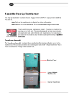
2.3 Multi-Tap Voltage Capability
The transfer switch voltage is factory-set. Check the
nameplate and confirm that the transfer switch has been
configured for the correct system voltage prior to
installation.
Note: Verify that the transfer switch voltage matches
the system voltage.
The transfer switch has multi-tap voltage capability at
the voltage transformers. See Figure 2-3 for a typical
transformer assembly. Figure 2-4 shows typical
connections. Refer to the wiring diagram provided with
the transfer switch for complete connection information
for your model.
To change the transfer switch voltage configuration, if
necessary:
D Before connecting power to the transfer switch,
change the voltage taps of the potential transformers
(PT’s) to match the system voltage. Refer to the
wiring diagram provided with the transfer switch.
D After the voltage taps have been set to correct
operating voltage, but before applying power to the
transfer switch, connect the contactor harness to the
controller through the control circuit isolation switch
on the transformer assembly. See Figure 2-3 and
Section 2.8.
D When power is connected to the ATS controller,
change the system voltage setting on the controller.
Refer to the transfer switch controller Operation
Manual, provided with the ATS, for instructions. See
the List of Related Materials in the Introduction
section for the document part number.
D Order a new nameplate from the Aftermarket Parts
department. Provide the ATS model and serial
numbers and the new voltage setting.
1. Cover (remove for access)
2. Engine start connection
3. Control circuit isolation switch
4. Voltage transformers
GM94796-1
4
1
2
3
Figure 2-3 Transformer Assembly, Typical (MCCB
Service Disconnect to OFF unit shown)
GM95677
Figure 2-4 Typical Voltage Tap Connections (Refer to the wiring diagram provided with the ATS.)

TP-6946 3/1616 Section 2 Installation
2.4 Set Overcurrent Protection
For models with integral overcurrent protection, the
overcurrent protection must be set prior to operation.
The equipment is shipped from the factory with a
long-time current setting of 100% (of the equipment
rating) and maximum short-time/ instantaneous current
and time delay settings.
Note: Do not energize this equipment until device
settings have been verified to ensure proper
system protection and coordination.
Refer to information supplied with the transfer switch for
adjustment procedures on the power switching unit’s
overcurrent protection trip unit.
Refer to Section 6.1.2, Overcurrent Trip, for additional
information on operation of the transfer switch following
an overcurrent trip condition.
2.5 Installation
NOTICE
Foreign material contamination. Cover the transfer switch
during installation to keep dirt, grit, metal drill chips, and other
debris out of the components. Cover the solenoid mechanism
during installation. After installation, use the manual operating
handle to cycle the contactor to verify that it operates freely.
Do not use a screwdriver to force the contactor mechanism.
The transfer switch may use both American Standard and
metric hardware. Use the correct size tools to prevent
rounding of the bolt heads and nuts.
Check the system voltage and frequency. Compare
the voltage and frequency shown on the transfer switch
nameplate to the source voltage and frequency. See
Section 2.3 if the system voltage is different from the
nominal normal (utility) source voltage.
Plan the installation. Use the dimensions given on the
enclosure dimension (ADV) drawings. Select a
mounting site that complies with local electrical code
restrictions for the enclosure type. Mount the transfer
switch as close to the load and power sources as
possible. Allow adequate space to fully open the
enclosure and to service the switch. Provide cable
bending space and clearance to live metal parts.
Outdoor installations. Transfer switches with
NEMA 3R and 4X enclosures can be installed outdoors.
In locations with very high ambient temperatures,
installation in a shaded area or a location with the
enclosure door facing away from direct sunlight is
recommended.
Prepare the foundation. Ensure that the supporting
foundation for the enclosure is level and straight. Refer
to the dimension drawing for required clearance.
For bottom cable entry, if used, install conduit stubs in
the foundation. Refer to the enclosure dimension
drawing for the conduit stub locations. When pouring a
concrete floor, use interlocking conduit spacer caps or a
wood or metal template to maintain proper conduit
alignment.
Installation of seismically certified transfer
switches. Seismic certification must be requested
when the transfer switch is ordered. See Section 2.6
and the transfer switch dimension (ADV) drawings for
additional installation requirements for transfer switches
with seismic certification.
Install the ATS. Refer to the dimension drawing
supplied with the switch and mount the transfer switch
according to the details and instructions on the drawing.
Smaller transfer switches have clearance holes through
the back of the enclosure for mounting. Bolt the transfer
switches to a wall or other rigid vertical supporting
structure. Use shims to plumb the enclosure. Verify that
the door hinges are vertical to avoid distortion of the
enclosure or door.
Bolt larger transfer switches directly to floor mounting
pads. Use shims to level the enclosure. Verify that the
door hinges are vertical to avoid distortion of the
enclosure or door.

TP-6946 3/16 17Section 2 Installation
2.6 Seismic Certification
Automatic transfer switches with seismic certification
must be installed according to the instructions in this
section. Also refer to ADV-7456, the Certificate of
Compliance provided with the ATS, and the installation
(ADV) drawings for the transfer switch.
Abbreviations:
ACI: American Concrete Institute
IBC: International Building Coder
S
DS:
Design spectral response acceleration at short
period, as determined in Section 1615.1.3 of
the IBC
R
p
: Equipment response modification factor
I
p
: Equipment importance factor
a
p
: In-structure equipment amplification factor
Refer to the International Building Coder for more
information.
General Seismic Installation Notes:
1. Anchors used for seismic installation must be
designed in accordance with ACI 355.2--04.
Suggested manufacturers include Simpson,
Ramset, and Hilti.
2. Anchors must be installed to a minimum
embedment of 8x the anchor diameter.
3. Anchors must be installed in minimum 4000 psi
compressive strength normal weight concrete.
Concrete aggregate must comply with ASTM C33.
Installation in structural lightweight concrete is not
permitted unless otherwise approved by the
structural engineer of record.
4. Anchors must be installed to the required torque
specified by the anchor manufacturer to obtain
maximum loading.
5. Anchors must be installed to the anchor spacing
required to obtain maximum load and edge
distance required to obtain maximum load unless
otherwise approved by the structural engineer of
record.
6. Anchors used for seismic installation must be
designed and rated to resist seismic loading in
accordance with ACI 355.2--04 and documented in
a report by a reputable testing agency (for
example, the Evaluation Service Report issued by
the International Code Council).
7. Wide washers must be installed at each anchor
location between the anchor head and equipment
for tension load distribution. See applicable ADV
drawing for specific anchor information and washer
dimensions.
8. Equipment installed on a housekeeping pad
requires the housekeeping pad thickness to be at
least 1.5x the anchor embedment depth.
9. All housekeeping pads must be seismically
designed and dowelled or cast into the building
structure as approved by the structural engineer of
record.
10. Rebar reinforcing in the housekeeping pad is
required for all installations.
11. Concrete and rebar reinforcing must be designed
in accordance with ACI 318--05.
12. Wall mounted equipment must be installed to a
rebar reinforced structural concrete wall that is
seismically designed and approved by the
engineer of record to resist the added seismic
loads from components being anchored to the wall.
13. Floor mounted equipment (with or without a
housekeeping pad) must be installed to a rebar
reinforced structural concrete floor that is
seismically designed and approved by the
engineer of record to resist the added seismic
loads from components being anchored to the
floor.
14. When installing to a floor or wall, rebar interference
must be considered.
15. Equipment attached to any structural floor other
than those constructed of structural concrete and
designed to accept the seismic loads from the
mounted equipment are beyond the scope of this
specification.
16. Installation to light-weight concrete over steel
decking is beyond the scope of this specification.
17. Installation to concrete block or cinder block walls
is beyond the scope of this specification.

TP-6946 3/1618 Section 2 Installation
2.7 Manual Operation Check
Hazardous voltage.
Will cause severe injury or death.
Only authorized personnel should
open the enclosure.
DANGER
Hazardous voltage.
Backfeed to the utility system can
cause severe injury, death, or
property damage.
Before energizing the transfer switch,
verify that both the normal and
emergency contacts are not left in the
closed position.
WARNING
Note: A manual operation handle is provided on the
transfer switch for maintenance purposes only.Do
not use the manual operation handle to transfer
the load with the power connected.
Use the manual operation handle to check the manual
operation before energizing the transfer switch. Check
the operation of both the Normal and Emergency
operators.
A power switching device in normal and serviceable
condition operates smoothly without binding. Do
not place the transfer switch into service if the power
switching device does not operate smoothly; contact an
authorized distributor/dealer for service.
Note: Refer to Figure 2-5 through Figure 2-7 for
identification of transfer switch mechanism style
supplied with the transfer switch.
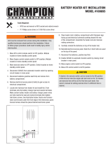
2.7.1 Manual Operation Test Procedure,
100--1200A MCCB Models
Manually operate the transfer switch mechanism,
depending on mechanism type, as described below.
100--800 Amp Units:
See Figure 2-5. Insert the operating handle into the
front of the transfer mechanism and turn the operating
handle until the position indication on the mechanism
clearly shows the desired position: generator, neutral,
or utility.
1000 and 1200 Amp Units:
See Figure 2-6. Pull the manual release knob on the
mechanism, releasing the motor drive rod from the
motor drive arm. Move the knob and yoke to the marked
position.
1
GM69173
2
1. Manual operation handle storage location
2. Insert handle here to operate manually
Figure 2-5 100--800 Amp MCCB Manual
Operation (250 Amp model shown)

TP-6946 3/16 19Section 2 Installation
1
1. Manual operation knob
2. Yoke
GM71058
2
Figure 2-6 1000--1200 Amp MCCB Manual
Operation
2.7.2 Manual Operation Test Procedure,
800--4000 A ICCB Models
See Figure 2-7. Manually operate the power switching
units as follows: Push the breaker’s TEST pushbutton.
The breaker should then open. Press the reset button to
reset the breaker.
Repeat for the other power switching unit.
1
ADV--7884
1. Trip (Test) and reset pushbuttons
1
Figure 2-7 ICCB Manual Operation

TP-6946 3/1620 Section 2 Installation
2.8 Controller Connections
Hazardous voltage.
Will cause severe injury or death.
Disconnect all power sources before
opening the enclosure.
DANGER
NOTICE
Electrostatic discharge damage. Electrostatic discharge
(ESD) damages electronic circuit boards. Prevent
electrostatic discharge damage by wearing an approved
grounding wrist strap when handling electronic circuit boards
or integrated circuits. An approved grounding wrist strap
provides a high resistance (about 1 megohm), not a direct
short, to ground.
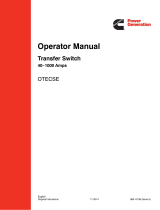
The controller is mounted in a plastic housing on the
inside of the transfer switch enclosure door.
Figure 2-8 shows the locations of the connectors on the
controller. It is not necessary to open the cover to
access the Ethernet, Modbusr, and input/output
connectors.
Opening the cover. If necessary, open the plastic
housing by pushing up on the latch on the bottom of the
cover and swinging the cover up and out. The cover is
hinged at the top. Lift the cover off the hinges to remove
it completely, if necessary.
Note: Always replace the cover before energizing the
transfer switch controls.
6
1. Standard input/output connection
2. RS-485 connection TB2
3. Connection for optional current sensing kit
4. Optional I/O module connection P16
5. Access openings to optional RJ-45 connector
6. Latch
7. Ground wire
8. Contactor harness connection (through controller circuit
isolation switch on transformer assembly. See Figure 2-3.)
5
GM85884
1
3
8
7
2
4
Figure 2-8 Controller
Modbus is a registered trademark of Schneider Electric.
/