
381333–272 B
50 Hanover Road, Florham Park, New Jersey 07932–1591 USA
For sales or service call 1 800 800–2726 (ASCO) www.ascopower.com
ASCO POWER TECHNOLOGIES CANADA PO Box 1238, 17 Airport Road, Brantford, Ontario, Canada N3T 5T3
telephone 519 758–8450, fax 519 758–0876, for service call 1 888 234–2726 (ASCO) www.asco.ca
Operator’s
Manual
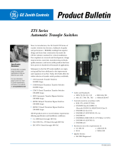
4000 Seri es ADTS
Automatic Delayed–Transition Transfer Switches
J–design 150–600A, H–design 800–1200A,
G–design 1600–3000A, F–design 4000A
DANGER is used in this manual to warn of high
voltages capable of cau si n g shock , burns, or death .
WARNINGisusedinthismanualtowarn
of possible personal injury.
CAUTIONisusedinthismanualtowarn
of possible equipment damage.
Refer to t he outline and wiring drawings provided
with your 4000 Series ADTS for all installation and
connection details and accessories.
Refer to Group 5 Controller U ser’s Guide 381333–126
for ATS status display messages, time delays, pickup
& dropout settings, and adjustments.
An ex perienced licensed electrician must install the ACTS.
Rating Label
Eac h autom atic clos ed– tran sition tran sfer sw itc h contains a
rating label to define the loads and fault circuit withstand /
cl osing ratings. R efer to the l abel on the transfer switc h for
spe cific val ues.
Do not exceed the values on the rating label.
Exceeding the rating can cause personal injury
or serious equipment damage.
Namepl ate
The Transfer Switch nameplate includes data for each
specific 4000 Series ADTS. Use the switch only within the
limits shown on this nameplate. A typical Catalog Number
is shown on the next page with its elements explained.
TABLE OF CONTENTS
section-page
INSTALLATION 1-1........................
Mounting a nd Line Connections 1-1.........
Auxiliary Circuits and Harness 1-2...........
Engine Starting Contacts 1-2...............
Functional Test 1-3 through 1-8..............
TESTING & SERVICE 2-1..................
Transfer Test 2-1..........................
Preventive Maintenance 2-1................
Disconnecting the Controller 2-1............
Manual Load Transfer 2-2..................
Trouble-Shooting 2-2......................
INDEX back cover.........................

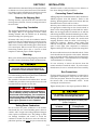
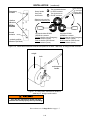
Catalog Number Identification
Ty pical 4000 Series catalog no. for J–design, 2 pole, 260 amp, 240 V, ADTS in Type 1 enclosure:
4ADTS A 2 260 F 5 C
Phase Poles
Neutral
A –solid
Amperes Voltage Controller Enclosure
B –switched
5X –if
accessories
ordered
5 –standard
G –type4
C –type1
F –type3R
H –type4X
3 –threeØ
2 –singleØ
B 120
D 220
A 115
C 208
E 230
K 415
M 460
J 400
L 440
N 480
G 277
F 240
H 380
Q 575
P 550
R 600
1200
2000
1000
1600
2600
3000
150
blank – none
blank – open type
J
design
prefix
letter
C – overlapping
600
800
260
4000
400
L –type12
Transfer
Switch
power
connections
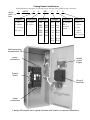
Group 5
Controller
transfer
control
&lights
J–design 260 ampere size in typical enclosure with location of customer connections
power
connections
field connections
terminal block TB

SECTION 1 INSTALLATION
1 --- 1
ASCO 4000 Series Automatic Delayed–Transition Trans-
fer Switches are factory wired and tested. Field i nstalla-
tion simply requires mounting and connection of service
cables, and auxiliary control circuits (if required).
Remove the Shipping Skid
For large switches, open t he front door and remove the
four lag screws (2 in front, 2 in rear) securing enclosure to
the wood skid.
Supporting Foundation
The supporting foundation for the enclosure must level
and straight. Refer to the applicable enclosure outline
drawing included with the 4ADTS for all mounting
details including door opening space.
If bottom cable entry i s used, the foundation must be
prepared so that the conduit stubs are located correctly.
Refer to the enclosure outline drawing for specified area
and location. Provide cable bending space and clearance
to live metal parts. When a concrete floor is poured, use
interlocking conduit spacer caps or a wood or metal
template to maintain proper conduit alignment.
Mounting
Refer to the outline and mounting diagram provided with
the ATS; it shows all mounting details and instructions.
Protect the switch from construction grit
and metal chips to prevent malfunction or
shortened life of the automatic switch switch.
Mount the ATS vertically to a rigid supporting structure.
L evel all mounting points by using flat washers behind the
holes to avoi d distortion of the switch.
The controlle r i s mounted on the cabinet door. An add-
on DIN rai l is provided for some optional accessories and
is mounted below controller on the door.
De–energize the conductors before making any
line or auxiliary circuitry connections. Be sure
that Normal and Emergency line connections
are in proper phase rotation. Place engine gen-
erator starting control in the OFF position. Make
sure engine generator is not in operation.
Te sting Power Conductors
Do not connect the power conductors to the transfer
switch until they are tested. Installing power cables in
conduit, cable troughs and ceiling-suspended hangers
often requires considerable force. The pulling of cables
can damage insulation and stretch or break the
conductor’s strands. For this reason, after the cables are
pulled into position, and before they are connected, they
should be tested to verify that they are not defective or
have been damaged during installation.
Connecting Power Conductors
A Wiring Diagramis furnished with the ASCO 4000 Series
4ADTS (separate from this manual). Refer to this
drawing. All wiring must be made in accordance with the
National Electrical Code and local codes.
After the power cables have been tested, connect them to
the appropriate terminal lugs on the transfer switch as
shown o n the wiring diagram provided wit h the switch.
Make sure the lugs provided are suitable for use with the
cables being installed. Standard terminal lugs are solder-
lessscrewtypeandwillacceptthewiresizeslistedonthe
drawings provided with the switch. Be careful when
stripping insulation from the cables; avoid nicking or
ringing the conductor. Remove surface oxides from
cables by cleaning with a wire brush. When aluminum
cable is used, apply joint compound to conductors.
Tighten cable lugs to the torque specified on rating label.
Do not run cables in front of or behind the switch. Cables
can be bundled on the right side of the switch. Maintain
proper electrical clearance between the live metal parts
and grounded metal: ½ inch minimum for 150-400 amps,
1 inch minimum over 400 amps.
It is not necessary to remove the barriers from the
transfer switches to install the cables. If you do remove
them,however, be sure to reinstall the barri ers carefully.
Bus Connections
For large switches use grade 5 hardware to connect bus to
appropriate terminal plates. Wipe off the bus surfaces
before they are joi ned. If the bus is very dirty, gently clean
the surfaces wit h a non---flammable solvent. Avoid
touching the cleaned surfaces.
Tighten bolted joints to the torque specified in Table A.
The reliability of the co nnection depends
on how clean and how tight the joint is.
Table A. Tightening torque values for bolted j oints
(Grade 5 hardware)
Bol t Diameter
in inches
Tightening Torque
in foot pounds
1/4 7
5/16 12
3/8 20
1/2 50
5/8 95
3/4 155

INSTALLATION (continued)
1 --- 2
Controller Ground
A grounding wire must be connected to the controller’s
lower left mounting stud. Because the controller is
mounted on the enclosure door, a conductive strap must
be used between the enclosure and the door. This
connection provi des proper grounding which does not
rely upon the door hinges.
Harnesses
The transfer switch is connected to the left side of the
control pa n el by a plug-in harness (two plugs).
Auxiliary Circuits
Connect auxiliary circuit wires to appropriate terminals
on the transfer switch. Note the control features that are
furnished on this switch. Make the necessary auxiliary
connections by referri ng to the Wiring Diagram.
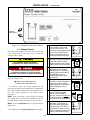
Engine Starting Contacts
The engine control contact connections (if used) are
located on the transfer switch. Connect signal wires to
appropri ate terminals as specified in Table B and shown
in Figures 1–1 and 1–2. See the wiring diagram too.
Table B. Engine start connections
When normal
source fails
Te rm ina l s o n
transfer switch
contact closes TB1 and TB2
contact opens TB1 and TB3
COMMON
FEATURE 7
closes to start
FEATURE 8
opens to start
COMMON
FEATURE 14B
closed on emergency
FEATURE 14A
closed on normal
COMMON
FEATURE 14BA
closed on emergency
FEATURE 14AA
closed on normal
Engine Starting
Signals
5amps,32VDC
5ampsresistive28VDC
or 120 V AC max.
TS Auxiliary Contacts
Feature 14A & 14B
10 amps, 32 V DC
10 amps 250 V AC
general purpose
Optional
TS Auxiliary Contacts
Feature 14AA & 14BA
10 amps, 32 V DC
10 amps 250 V AC
general purpose
left side of transfer switch
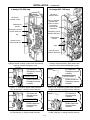
Figure 1-1. Connections to engine starting contact
terminal block for 150 through 1200 amp.
J & H–design transfer switches.
TB Terminal Block
(field connections)
accepts wire range
22–12 AWG
Engine Starting
Signals
5amps,32VDC
5ampsresistive28VDC
or 120 V AC max.
TS Auxiliary Contacts
Feature 14A & 14B
10 amps, 32 V DC
10 amps 250 V AC
general purpose
FEATURE 7
closes to start
FEATURE 8
opens to start
Figure 1-2. Connections to engine starting contact
terminal block located on 1600 th rough 3000 amp.
G–design transfer switches.

INSTALLATION (continued)
1 --- 3
Functional Test
The Functional Test consists of t hree checks:
❐ 1 — Manual Operation Test , pages 1–3 through 1–6
❐ 2—VoltageChecks,page1–7
❐ 3 — Electrical Operation, page 1–8
Do these checks in the order presented
to avoid damaging the ATS.
Read all inst ructions on the Wiring Diagram and labels
affixed to the ATS. Note the control features that are
provided and review their operation before proceeding.
Continue to 1–ManualOperationTest starting below.
1 – Manual Operation Test
A detachable operator handle is provided on the transfer
switch fo r mai ntenanc e pur poses only.Manualoperation
of the transfer switch must be checked before it is
operated electrically.
Do not manually operate the transfer switch
until both power sources are disconnected:
open both circuit breakers.
1. Select the appropriate switch design / amp. size and
follow directions for installing and using the handle:
150–1200 amp J, H–designs Fig. 1-3, -4, -6 thru -11.
Attach the manual handle onto the shaft hub, left
side of the operator.
1600 – 3000 amp. G–design See Figures 1-5, 1-12.
Install the hub (with pin
) onto the shaft and inse rt the
manualfirmlyintothesideholeinthehub. Pushin
or pull out hub to engage opposite source contacts.
4000 amp. F–design SeeFigure1-13.
Insert the manual handle into the hole in the weight.
2. Move the handle as shown to manually operate the
Transfer Switch. The switch should operate smooth-
ly without binding. If it does not, check for shippi ng
damage or construction debris. Re peat the manual
operation check on the other Transfer Switch.
3. Return the tran sfer switch to the N (closed on normal)
position. If removable, remove the maintenance
handle and store it on the transfer switch in the place
provided.
window indicators
O is open
C is closed
Emergency contacts
(upper shaft)
Normal contacts
(lower shaft)
contact
position
indicators
(right side)
Figure 1-3. Contact position indicators on
150–600 amp. J–design transfer switches .
Shown with Emergency open and Normal closed.
window indicators
O is open
C is closed
Emergency contacts
(upper shaft)
Normal contacts
(lower shaft)
contact
position
indicators
(right side)
Figure 1-4. Contact position indicators on
800–1200 amp. H–design transfer switches .
Shown with Emergency open and Normal closed.
window
indicators
OPEN or
CLOSED
Emergency
contacts
Normal
contacts
contact
position
indicators
(left side)
Figure 1-5. Contact position indicators on
1600–3000 amp. G–design transfer switches .
Shown with Emergency closed and Normal open.

INSTALLATION (continued)
1 --- 4
maintenance
handle
left side of
transfer switch
clip
Emergency source
contact shaft hub
Normal source
contact shaft hub
J–design 150–600 amp
Figure 1-6. Maintenance handle on 150–600 amp.
J–design transfer switches. Hubs shown with Normal
contacts clos ed & Emergency open.
handle
hub
UP opens the
Emergency source
contacts
DOWN closes the
Emergency source
contacts
frame
UPPER SHAFT
Figure 1-7. Emergency (upper shaft) operation
on 150–600 amp. J–design transfer switches.
handle
hub
UP closes the
Normal source
contacts
DOWN opens the
Normal source
contacts
frame
LOWER SHAFT
Figure 1-8. Normal (lower shaft) operation
on 150–600 amp. J–design transfer switches..
maintenance
handle
left side of
transfer switch
clips
Emergency source
contact shaft hub
Normal source
contact shaft hub
lobes on weights
prevent both
N&Econtacts
from being
closed at the
same time
H–design 800–1200 amp
Figure 1-9. Maintenance handle on 800–1200 amp.
H–design transfer switches. Hubs shown with
Normal contact s closed & Emergency open.
handle
hub
UP opens the
Emergency source
contacts
DOWN closes the
Emergency source
contacts
frame
UPPER SHAFT
Figure 1-10. Emergency (upper shaft) operation
on 800–1200 amp. H–design transfer switches.
handle
hub
UP closes the
Normal source
contacts
DOWN opens the
Normal source
contacts
frame
LOWER SHAFT
Figure 1-11. Normal (low er shaft) operation
on 800–1200 amp. H–design transfer switches..

INSTALLATION (continued)
1 --- 5
Do not manually operate the transfer switch
until both power sources are disconnected:
open both circuit breakers.
Table C. Maintenance handle positions on 150–1200 amp. transfer switches. .
Transf er Switch
Position
J–design 150---600 A
Interlocked Shafts
1
Link between contact
shafts prevents closing
both N & E contacts
H–design 800---1200 A
Interlocked Weights
2
Lobes prevent
closing both N & E
contacts
Maintenance
Handle
Shaft Indicators
N
o
r
m
a
l
E
t
t
h
f
t
hub
l
o
b
e
l
o
b
e
weight
hub
up
E=O
upper contacts open
N
orma
l
N
link
contact sha
f
ts
hub
l
o
b
e
l
o
b
e
weight
hub
up
N=C
lower contacts closed
Load
E
up
E=O
upper contacts open
L
o
a
d
Disconnected
N
down
N=O
lower contacts open
E
m
e
r
g
e
n
c
y
E
down
E=C
upper contacts closed
E
mergency
N
down
N=O
lower contacts open
Note 1: The hub and contact shaft turn in oppo site directio ns through a cam follo wer mechanism.
Note 2: The hub and contact shaft turn in the same directio ns.
Note: If Normal and Emergency connecti ons are reversed this operation is also reversed.

INSTALLATION (continued)
1 --- 6
clockwise DOWN
OPENS the contacts
Pull out
shaft to close Emergency
source contacts (upper)
Push in
shaft to close Normal
source contacts (lower)
counterclockwise DOWN
OPENS the contacts
Pull out
shaft to open Emergency
source contacts (upper)
Push in
shaft to open Normal
source contacts (lower)
window
indicators
OPEN or
CLOSED
Emergency
contacts
Normal
contacts
contact position
indicators (left side)
Turn counterclockwise
to OPEN contacts.
Turn clockwise to
CLOSE contacts.
Insert handle
into hole
(spring fully
compressed)
Grasp handle
firmly with
both hands
Slide the hub onto the
shaft and insert the pin
.
Figure 1-12. Removable maintenance handle and positions on 1600 – 3000 amp. G–design transfer switches.
maintenance
handle
weight
hole
Figure 1-13. Removable maintenance handle on
4000 amp. F–design transfer switch.
Verify that the maintenanc e handle has been
removed and stored properly before proceeding!
Now continue to 2–VoltageCheckson page 1–7.

INSTALLATION (continued)
1 --- 7
observe
these lights
Press for 15 Sec.
Figure 1-14. Standard controls and indicators.
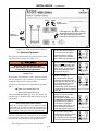
2 --- V o l t a g e C h e c k s
First check the nameplate on the transfer switch; the
rated voltage must be the same as the normal and
emergency line voltages.
Verify that the feeders have been
connected to the proper terminal lugs.
Useextremecautionwhenusingameter
to measure voltages. Do not touch power
terminals; shock, burns, or death could result !
Perform steps 1 through 6 at the right. Observe the stat us
lights. See Figure 1–14.
● Black circle means light is on.
❍ White circle means light is off.
* If necessary, adjust the voltage regulator on the
generator according to the manufacturer’s recommenda-
tions. The a utomatic transfer switch will respond only to
theratedvoltagespecifiedonthetransferswitch
nameplate.
Note: Re fer to Section 3 of the Group 5 Controller
User’s Guide 381333–126 for how to display the status of
the ATS and the voltage and freq uency of each source.
Note: Press the Lamp Test button to verify that all five
lights work.
Now continue to 3 --- Electr ic al Operati on on next page.
1
Close the normal source (utility)
circuit breaker. Two two left
lights should come on. The
normal source Accepted (upper
left) and the Transfer Switch
Position connected to normal
(lower left) lights should be on.
2
Carefully use an accurate
voltmeter to check the phase to
phase and phase to neutral
volt ages present at the transfer
switch normal source terminals.
3
Close the emergency source
(generator) circuit breaker.
(Start generator, if necessary.)
Another light should come on.
The emergency source
Accepted light (upper right)
should be on.
4
Carefully use an accurate
voltmeter to check the phase to
phase and phase to neutral
volt ages present at the transfer
switch emergency source
terminals.*
5
Carefullyuseaphaserotation
meter to check the phase
rotation of the emergency
source; it must be the same
as
the phase rotation of the normal
source (refer to wiring diagram).
A
B
C
6
Shut down the generator, if
applicable. The emergency
source Accepted light (upper
right) should go off. Then set
the generator’s starting control
switch to automatic.Removeall
meters; close enclosure door.

INSTALLATION (continued)
1 --- 8
observe
these lights
press
these buttons
step 2 step 4
If this light is on, the buttons will not
work until the controls are unlocked.
If this light is blinking, the user
controls are unlocked for 5 minutes.
Press for 15 Sec.
Figure 1-15. User controls and indicators.
3 --- Electrical Operation
This procedure will check the electrical operation of the
automatic transfer switch. See Figure 1–15.
Be sure to close the enclosure door
before proceeding to prevent personal injury
in case of electrical system fault.
Transfer Test
Both normal and emergency sources must be available
and the emergency source generator (if used) must be
capable of being started in this procedure.
Perform steps 1 through 5 at the right. Observe the status
lights.
● Black circle means light is on.
❍ White circle means light is off.
If the User Controls Locked light is on, the Transfer Test
and Retransfer to Normal buttons will not work unti l you
unlock them.
How to unlock the User Controls
Press up or down arrow keys on Transfer Control
Center (Group 5 Controller), enter the password, and
press Enter key. The user controls are now unlocked
for 5 minutes. During that time the light will blink.
To lock or unlock the user controls refer to the Group 5
Controller User’s Guide 381333–126. Password informa-
tion and time delay settings are also provided there.
This completes the functional test of the ATS.
1
The two left lights should be on;
the normal source Accepted
(upper left) and the Transfer
Switch Position connected to
normal (lower left) should be on.
2
Press and hold the Transfer Test
button until the generator starts
and runs (this should happen
within 15 sec.). The emergency
source Accepted light (upper
right) should come on.
3
Then the transfer switch should
operate to emergency.
The Transfer Switch Position
connected to emergency light
(lower right) should come on and
the connected to normal light
(lower left) should be off.
IfFeature2Bisused,thetransfer
to emergency will occur after the
time delay.
4
The transfer switch should
operate back to normal after
Feature3Atimedelay.
Forimmediateretransferpress
the Retransfer to Normal button.
The Transfer Switch Position
connected to normal light
(lower left) should come on and
the connected to emergency
(lower right) light should be off.
5
The generator will stop after
Feature2Etimedelay(unloaded
running engine cooldown).
The emergency source Accepted
light (upper right) should go off.

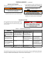
SECTION 2 TESTING & SERVICE
2 --- 1
TRANSFER TEST
Operate the 4000 Series ADTS at least once a month by
following the five–step Electrical Operation Transfer
Tes t procedure on page 1–7.
PREVENTIVE MAINTENANCE
Reasonable care in preventive maintenance will insure
high relia bility and long life for the 4000 Se ries ADTS.
An annual preventive maintenance program is recom-
mended.
ASCO Services, Inc. (ASI) is ASCO Power
Technologies’s national service organization. In the
US ASI can be contacted at 1-800-800-2726 for in-
formation on preventive maintenance agreements.
Checklist f or Yearly Inspection
Hazardous voltage capable of causing shock,
burns, or death is used in this transfer switch.
Deenergize both Normal – Emergency power
sources before p erforming inspections!
❐ Clean the 4ADTS enclosure. Brush and vacuum
away any excessive dust accumulation. Remove any
moisture with a clean cloth.
❐ Check the transfer switch contacts.Removethe
transfer switch barriers and check contact condition.
Replace the contacts if they become pitted or worn
excessively. Reinstall the barriers carefully.
❐ Maintain transfer switch lubrication.Ifthe
transfer switc h is subjec ted to severe dust or
abnor m al operating conditions, renew factory
lubrication on all movements and linkages.
Relub r ic ate the solenoid oper ator if the TS coil is
replaced. Do not use oil; order lubrication kit 75-100.
❐ Check all cable connections & retighten them.
REPLACEMENT PARTS
Replacement parts are available in kit form. When or-
dering parts provide the Serial No., Bill of Material No.
(BOM), and Catalog No. from the transfer switch name-
plate. Contact your local ASCO Power Technologies
Sales Office or ASI:
In the United States
call 1 – 800 – 800 – ASCO ( 2726 )
In Canada
call 1 – 888 – 234 – ASCO ( 2726 )
DISCONNECTING THE CONTROLLER
The harness disconnect plugs are furnished for repair
purposes only and should not have to be unplugge d. If
the controller must be isolated, follow these steps:
Disconnecting the Plugs
Do not unplug the controller
until steps 1a or 1b is completed.
1. Observe the position of the t ransfer switch.
a. If the trans fer switch is in the Normal position, first
place standby eng ine starting control in the off
position. Second, then open the emerg ency source
circuit breaker. Third, open the normal source
circuit breaker.
b. If the transfer switch is in the Emergency position,
first open the normal source circuit breaker. Se c-
ond, place the engine starting control in the test
or run position. Third, open the emergency source
circuit breaker.
2. Separate the two q uick disconnect plugs by squeez-
ing the latches. Do not pull on the harness wires.
Reconnecting the Plugs
Do not reconnect the controller
until steps 1a or 1b is completed.
1. Observe the position of the t ransfer switch.
a. If the transfer switch is in the Normal position,
firstbesurethatboth
normal and emergency
source circuit breakers are open. Second, be sure
that the standby engine starting control is still in
the off position.
b. If the transfer sw itc h is in the Emergency position,
firstbesurethatboth
normal and emergency
source circuit breakers are open.
2. The two harness plugs and sockets are keyed. Care-
fully align the plugs with the sockets and press
straight in until both latches click. Close the door
!
3. Restore the two sources in sequence as follows:
a. If the transfer switch is in the Normal position,
first close the normal source circuit breaker.
Second, close the emergency source circuit break-
er. Third, place the standby engine starting
control i n the automatic position.
b. If the transfer switch is in the Emergency position,
first close the emergency source circuit breaker.
Second close the normal source circuit breaker.

TESTING & SERVICE
(continued)
2 --- 2
MANUAL LOAD TRANSFER
This procedure will manually transfer the load if the
controller is disconnected.
Do not manually operate the transfer switch
until both power sources are disconnected
(all conductors deenergized).
1. Deenergize both the normal and emergency source
conductors (remove fuses or open circuit breakers).
2. Use the maintenance handle to manually operate the
transfer switch to the opposite source. First open the
closed contacts, then close the other contacts. Do no
t
try to c l ose both Norm al and Emerg en c y co ntac t
.See
Manua l Opera tion on page 1–3 through 1–6.
3. Then remove
the maintenance handle..
Verify that the maintenance handle
has b een removed before proceeding!
4. If the transfer switch is in the Emergency position
manually start the engine generator and then install
emergencysourcefuseorclosethecircuitbreaker.
TROUBLE-SHOOTING
Note any optional accessories that may be furnished on
the ADTS and review their operation. Refer to any
separate drawingsand/orinstructions that may bepacked
with the ADTS.
Hazardous voltage capable of causing shock,
burns, or death is used in this switch.
Do not touch the power or load terminals
of the transfer switch!
Table 2-1. Trouble-Shooting Checks.
P
R
O
B
L
E
M
CHECK IN NUMERICAL SEQUENCE
P
R
O
B
L
E
M
1OPERATION 2 GEN-SET 3VOLTAGE
Engine–generator set does
not start when the Transfer
Control switch is turned and
held
in Transfer Test position
or when normal source fails.
Hold T ransfer Test switch 15
seconds or the outage must
be long enough to allow for
Feature1Ctimedelayplus
engine cranking and star ting.
Starting control must be in the
automatic position. Batteries
must be charged and
connec ted. Check wiring to
engine starting contacts.
---
Transfer switch does not
transfer the load to the
emergency source after the
engine–generator set starts.
W ait for Feature 2B time delay
to time out.
Generator output circuit
breaker must be closed.
Generator frequency must be
at least 95% of nominal (57 Hz
for a 60 Hz system.) *
Voltmeter should read at least
90% of nominal phase to
phase voltage between
terminals EA and EC (or EL1
and EL2 for 2 po le switches)*
Transfer switch does not
transfer the load to normal
source when normal returns
or when the Transfer Control
switch is released.
W ait for Feature 3A time delay
to time out.
---
Voltmeter should read at least
90% of nominal phase to
phase voltage between
terminals NB and NC, NC and
NA , and NA and NB (or NL1
and NL2 for 2 po le switches).
Gen. does not stop after load
retransfer to normal source.
W ait for Feature 2E time delay
to time out.
Starting control must be in the
automatic position.
---
* These are factory settings. Refer t o Group 5 Controller User’s Guide.
If the problem is isolated to circuits on the controller or the transfer switch, call your local ASCO Power Technologies
sales office or ASI: in the United States, call 1–800–800–2726 or in Canada call 1–888–234–2726. Furnish the Serial No.,
Catalog No., and Bill of Material (BOM) No. from the transfer switch nameplate.

INDEX
Printed in U.S.A. ASCO Power Technologies, L.P. 2007
A
auxiliary circuits, 1–2
C
cable
lugs, 1–2
preparation, 1–2
catalog number, inside cover
cleaning, 2–1
connections
line, 1–1
contact position indicators, 1–3
controller, 1–1
disconnecting, 2–1
see Controller User’s Guide
E
electrical operation, 1–8
emergency source accepted light,
1–7
engine starting contacts, 1–2
F
frequency, generator, 2–2
functional test, 1–3 through 1–8
G
ground, controller, 1–1
H
harness, 1–1
disconnect plugs, 2–1
HELP
customercare@asco.com
800–800–ASCO
I
indicators, contact position, 1–3
inspection, 2–1
installation, 1–1
interlocked weights, 1–6
L
labels,
engine start contacts, 1–2
rating, cover
lights, 1–7, 1–8
Lo ad Disconnected light, 1–8
load disconnected, 1–3
lubrication, 2–1
M
maintenance handle, 1–3 through –6
maintenance, preventive, 2–1
manual load transfer, 2–2
warning, 2–2
manual operation, 1–3, 1–4, 1–5, 1–6
illustration of, 1–3, 1–4, 1–5, 1–6
warning, 1–3
N
nameplate, cover
normal source accepted light, 1–6
O
operation
electrical, 1–7
manual, 1–3, 1–4, 1–5, 1–6
illustration of, 1–3, 1–4, 1–5, 1–6
warning, 1–3
optional accessories
see Controller User’s Guide
P
parts, 2–1
phase rotation check, 1–5
problem, 2–2
R
rating label, cover
replacement parts, 2–1
S
service
in the U.S call 1–800–800–2726
in Canada call 1–888–234–2726
settings
see Controller User’s Guide
shaft indicators, 1–3
T
test, functional, 1–3 through 1–8
time delays, 2–1
see Controller User’s Guide
transfer swi tch connected to emer-
gency light, 1–8, 2–1
transfer switch connected to normal
light, 1–8, 2–1
transfer switch posi tions, 1–3
Transfer Test, 1–8
transfer to emergency, 1–8
transfer to normal, 1–8, 2–1
trouble–shooting, 2–2
U
user controls and indicators
Retransfer to Normal, 1–8
Transfer Test, 1–8
V
voltage checks, 1–7
voltage, pickup and dropout settings
see Controller User’s Guide
-
 1
1
-
 2
2
-
 3
3
-
 4
4
-
 5
5
-
 6
6
-
 7
7
-
 8
8
-
 9
9
-
 10
10
-
 11
11
-
 12
12
-
 13
13


Ask a question and I''ll find the answer in the document
Finding information in a document is now easier with AI
Related papers
-
Emerson E-DESIGN 150-400A User manual
-
Emerson 7000 User manual
-
-
-
-
-
-
-
-
Other documents
-
Trendnet Series 300 User manual
-
Simplicity 071112 User manual
-
Simplicity 071098 User manual
-
Schneider Electric 300 Series User manual
-
Kohler KCC Operating instructions
-
Infocus Switch 165 User manual
-
-
CAT LEHE4651-04 User manual
-
 3G Green Green Globe ZTSCT100 User manual
-
Eaton Magnum Transfer Switch User manual
