Makita BFL201F User manual

Category
Power tools
Type
User manual

Makita BFL201F is a cordless angle screwdriver designed for fastening works, particularly in assembly lines. It features a powerful 14.4V/3.0Ah Li-ion battery and a BLDC motor for efficient operation. The screwdriver offers precise torque control with a range of 8 - 20 N.m and a no-load speed of 360 rpm. It comes with a standard square 9.5 (3/8) driving shank, soft start, LED job light, electric brake, reversing switch, and torque adjustment. The BFL201F is well-suited for various applications, including carpentry, metalworking, and automotive assembly.

Makita BFL201F is a cordless angle screwdriver designed for fastening works, particularly in assembly lines. It features a powerful 14.4V/3.0Ah Li-ion battery and a BLDC motor for efficient operation. The screwdriver offers precise torque control with a range of 8 - 20 N.m and a no-load speed of 360 rpm. It comes with a standard square 9.5 (3/8) driving shank, soft start, LED job light, electric brake, reversing switch, and torque adjustment. The BFL201F is well-suited for various applications, including carpentry, metalworking, and automotive assembly.

Specification
Standard equipment
Optional accessories
L
H
W
No
Battery BL1430
Battery BL1430A
Fast charger DC18RA
Charger DC18SD
Charger DC24SC
Automotive Charger DC18SE
Auto refresh adapter ADP03
Battery protector (for BL1430A)
Protectors (red/ blue/ yellow/ clear)
Torque adjust tool
Angle head set
Dimensions: mm (")
Width (W)
Height (H)
Length (L) 429 (16-7/8)
98 (3-7/8)
72 (2-13/16)
Model No.
Description
PRODUCT
CONCEPT AND MAIN APPLICATIONS
P 1/ 13
BFL201F
Cordless Angle Screwdriver 14.4V
This cordless angle screwdriver for fastening works in assembling line is
developed as an advanced model of BFL200F.
Additionally to the same tool durability and high fastening torque accuracy
as the current series models, these products feature a powerful and efficient
power source and power unit, namely 14.4V/ 3.0Ah Li-ion battery* and
BLDC motor (Brushless DC motor).
BFL201F
Model
Specifications
No load speed: rpm= min
-1 360
370
1.7 (3.8)
Battery
Driving shank: mm (")
Weight according to
EPTA-Procedure 01/2003* : kg (lbs)
LED Job light
Torque adjustment
Reversing switch
Electric brake
Soft start
Torque range: N.m (in.lbs) 8 - 20 (71 - 177)
Yes
Yes
Yes
Yes
Yes
Square 9.5 (3/8)
Cell
Voltage: V
Capacity: Ah
Li-ion
14.4
3.0
Max output: W
* with Battery BL1430
T
ECHNICAL INFORMATION
This product is available in the following specifications
with the model number described below.
BFL201FZ No No
Model No.
type quantity
Charger
No
Battery
cover
No
Battery
*BL1430 and BL1430A can be used,
but 1.3Ah Li-ion battery BL1415 cannot be used.
P 2/ 13
Repair
[1] NECESSARY REPAIRING TOOLS
[2] LUBRICATIONS/ GLUING
Fig. 1
Code No. Description Use for
Item No.
Apply Makita grease N.No.2/ Loctite 603 to the portions designated by arrows.
Description Portion to lubricate
1R314 Torx bit VT-25
1R173 Retaining ring R pliers RT-1 Removing/installing Retaining ring R-22
1R034 Bearing setting plate 12.2 Installing Ball bearing 6900LLB
1R041 Vise plate Protecting parts when holding in vise
1R145 L-type torx wrench Loosening/tightening M5x10 Torx countersunk head screw
1R219 Torque wrench shaft 7-23N.m Installing Bearing retainer
1R220 Ratchet head 9.5 (for 1R219) Installing Bearing retainer
Installing Bearing retainer1R222 Socket adapter
Removing Ball bearing 6900LLB1R269 Bearing extractor
1R288 Screwdriver Magnetizer Magnetizing Screwdriver for removing Steel balls
1R291
Retaining ring S and R pliers Removing/installing Retaining ring S-10
Loosening/tightening M5x10 Torx countersunk head screw
134861-3 Socket 24-45 Installing Bearing retainer
765027-4
783204-6
Torque adjust tool Disassembling Clutch assembly
Hex wrench 6 (flats width: 6mm) Loosening/tightening Adjust ring complete
Spindle A complete Gear teeth that engages with Spiral bevel gear 9
Spindle Left hand where M12 Lock nut contacts
Gear teeth and three shaft pins
Gear teeth
Steel ball 5.0 (3pcs.)
Steel ball 4 (3pcs.)
Whole surface
Steel ball 3 (13pcs.)
O ring 14
Spur gear 18 (3pcs.)
Spur gear 9 complete A
Spur gear 18 (3pcs.)
Three shaft pinsCarrier complete B
Gear teeth
13
28
14
17
19
42
35
41
40
37
Item No. Description Portion to glue Adhesive
Bearing retainer 14-23
Torx C.S.H. screw M5x10
36
M3x20 Pan head screw (7pcs.)
86
M4x22 Pan head screw (4pcs.)
Note: Part No. for 40 is different from that for 42 .
2
21
M4x8 Pan head screw
Thread
25 26
CAUTION: Repair the machine in accordance with “Instruction manual” or “Safety instructions”.
Lubricant Amount
Amount
a little
a little
a little
Makita grease N.No.2
2g
2g in
total
Loctite 603
2
Spiral
bevel
gear 9
25
26
M12 Lock nut
13
14
17
19
21
28
35
36
37
40
41
42
Housing L
86
P 3/ 13
Repair
[3] DISASSEMBLY/ASSEMBLY
[3]-1. LED job light section
DISASSEMBLING
M4x8 Pan head screw (2pcs.) Light cover
1) Remove Light cover by unscrewing two M4x8 Pan head screws. (Fig. 2)
2) Remove LED circuit and its Lead wires from Light holder, and disconnect Connector of LED circuit with that of
Motor control unit. Switch lever and Compression spring 2 can be removed in this step. (Fig. 3)
Connector of
LED circuit
Connector of
Motor control
unit
LED circuit
Lead wire
Light holder
Compression spring 2 Switch lever
Fig. 2 Fig. 3
RibSwitch unitLead wire holders
Fig. 5Fig. 4
Light cover protrusion Notch of Angle
head complete
Note: Put Connectors and the slack portion of Lead wires in
this space. Do not put them on Switch unit and the rib.
[3] -2. Spindle A complete section
DISASSEMBLING
Fig. 9Fig. 8
24mm
Fig. 6 Fig. 7
Bearing retainer 14-23
Angle head complete
Bearing retainer 14-23
Spindle A complete
Bearing retainer 14-23
Spindle A complete
Spindle A
complete
Flat washer 6
Wrench
1) Connect Connector of LED circuit with that of Motor control unit. and put LED circuit in place on Light holder.
Then fix lead wires with Lead holders as illustrated in Fig. 4.
2) Fitting the protruding portion of Light cover in the notch of Angle head complete, assemble Light cover to
Angle head complete by screwing two M4x8 Pan head screws. (Fig. 5)
Note: Be careful not to pinch the slack portion of Lead wires between Light cover and Angle head complete.
ASSEMBLING
1) Remove Bearing retainer 14-23 from Angle head complete by turning clockwise with wrench of 24mm flats width.(Fig. 6)
Spindle A complete section can now be removed by pulling by hand. (Fig. 7)
2) Remove Flat washer 6 from Spindle A complete. (Flat washer 6 may remain in Angle head complete.)
Remove Spindle A complete from Bearing retainer 14-23 by pushing down Bearing retainer 14-23 in the direction of
the arrow by hand. (Fig. 8)
Note: If cannot be removed by hand, disassemble by pressing down Spindle A complete using arbor press. (Fig. 9)
Spindle A complete section
Bearing
retainer 14-23
P 4/ 13
Repair
[3] DISASSEMBLY/ASSEMBLY
[3] -2. Spindle A complete section (cont.)
1) Apply Makita grease N.No.2 to O ring 14. (Fig. 1)
Assemble O ring 14, Flat washer 14 then Spindle complete to Bearing retainer 14-23 as illustrated in Fig. 10.
Note: If you cannot assemble Spindle complete to Bearing retainer 14-23 by hand, do it using arbor press as illustrated in
Fig. 11.
2) Apply about 2g of Makita grease N.No.2 to the Gear room of Angle head complete. (Fig. 1)
Note: Be careful not to put Makita grease N.No.2 on the threaded portion of Angle head complete.
3) Apply Loctite 603 to the threaded portion of Bearing retainer 14-23. (Fig. 1)
Then assemble Flat washer 6 to Spindle complete. (Refer to Fig. 8.)
Assembling of Spindle complete section has been completed.
4) Clamp the flats of Angle head complete securely in a vise to which 1 set of 1R041 is attached, then assemble Spindle A
complete section to Angle head complete by turning Bearing retainer 14-23 counterclockwise using 1R219, 1R220, 1R222
and 134861-3 as illustrated in Fig. 11.
Caution: When clamping Angle head complete, be very careful not to deform it by overtightening.
ASSEMBLING
Fig. 11Fig. 10
Recommended tightening torque:
30 to 50N.m
1R2191R220
1R222
134861-3
1R041
Bearing retainer 14-23
O ring 14
Flat washer 14
Spindle A complete
P 5/ 13
Repair
[3] DISASSEMBLY/ASSEMBLY
[3] -3. Spiral bevel gear 9 section
1) Remove Light cover by unscrewing two M4x8 Pan head screws, then remove Switch lever and Compression spring 2.
(Fig. 12)
2) Remove Angle head complete from Housing by unscrewing four M4x22 (+) Pan head screws, then remove Clutch
section (= Clutch assembly) from Angle head complete. (Fig. 13)
Note: Be careful not to lose Compression spring 5, which may pop out from Clutch section when Clutch section is
removed from Angle head complete. (Fig. 13)
DISASSEMBLING
ASSEMBLING
Fig. 13Fig. 12
Fig. 15Fig. 14
Fig. 16
3) Using 1R173, remove Retaining ring R-22
that retains Spiral bevel gear 9 section in
Angle head complete. (Fig. 14)
Spiral bevel gear 9 section can now be
removed by tapping the end surface of
Angle head complete with plastic
hammer. (Fig. 15)
Compression spring 5
Retaining ring R-22
Spiral bevel
gear 9 section
Angle head complete
M4x22 (+) Pan head screws (4pcs.)
Housing
Clutch section
(= Clutch assembly)
Switch lever
Compression spring 2
Light cover
4) Remove Retaining ring S-10 using 1R291, then remove Ball bearing 6900LLB using 1R269.
Spacer and Needle bearing 1210 can now be removed from Spiral bevel gear 9. (Fig. 16)
1R291Retaining ring S-10
Ball bearing 6900LLB
1R269
Spacer
Needle baring 1210
Spiral bevel gear 9
1R173
Do the reverse of the disassembling steps. (Refer to Figs. 16 to 12.)
Note 1: Spacer is not reversible when assembled to Spiral bevel gear 9.
Be sure to assemble as illustrated to left in Fig. 17.
Note 2: Use 1R034 and arbor press when assembling Ball bearing 6900LLB to Spiral bevel gear 9. (Fig. 18)
Fig. 18Fig. 17
Spacer
Needle baring 1210
Ball bearing 6900 LLB
1R034
Arbor press
Spiral bevel gear 9
Spacer
Needle baring 1210
Spiral bevel gear 9
[Correct] [Wrong]
P 6/ 13
Repair
[3] DISASSEMBLY/ASSEMBLY
[3] -4. Clutch section
Fig. 22
M5x10 Torx countersunk
head screw
M5x10 Torx countersunk
head screw
783204-6
T25 Torx wrench (T25 of 1R145)
6mm
Spindle
Flat washer 7
Cam A on Torx screw side
Cam D
Cam A on Torx
screw side
Cam A on Torx screw side
Cam D
Spindle
Fig. 21
Steel ball 4 (3pcs.) Steel ball 5.0 (3pcs.)
Steel ball 4 (3pcs.) and Steel ball 5.0 (3pcs.)
can be removed by moving Cam D towards
the threaded end of Spindle.
After removing Steel ball 4 (3pcs.) and Steel ball 5.0 (3pcs.),
Steel ball 3 (13pcs.) can be removed by moving *the Cam on
Torx screw side towards Cam D.
Steel ball 3.0 (13pcs.)
Cam D
Note: When repairing Clutch section, it is recommended to entirely replace Clutch assembly with new one.
However, if required to replace component parts of Clutch assembly, follow the disassembling/assembling
procedure described below.
1) Take out Clutch section (=Clutch assembly) from Angle head complete. (Refer to Figs. 12 and 13)
2) Insert 765025-8 into the hole of Adjust ring complete, and turn it counterclockwise to remove M12 Lock nut:
the pressure of Compression spring 19H will be decreased, and M12 Lock nut can now be removed by turning it
clockwise by hand. (Fig. 19)
3) Remove Adjust ring complete, Flat washer 18, Compression spring 19H from Spindle. (Fig. 20)
4) The following Steel balls can be removed as illustrated in Fig. 21:
Steel ball 3 (13pcs.), Steel ball 4 (3pcs.), Steel ball 5.0 (3pcs.)
Note: Use a screwdriver magnetized with 1R288 for easy removal of Steel balls.
5) Insert short leg of hex wrench 6 into the hole of Spindle, and fix long leg of the hex wrench securely in vise.
Insert No.T25 Torx wrench of L type Torx wrench set (1R145) into the socket of M5x10 Torx countersunk head screw.
Then remove the screw by turning M5 Torx wrench counterclockwise as illustrated to left in Fig. 22.
The following parts can now be removed from Spindle: Cam D, Cam A on Torx screw side, Flat washer 7.(right in Fig. 22)
DISASSEMBLING
Flat washer 18
Compression
spring 19H
Compression spring 19H
Adjust ring
complete
Fig. 20
Fig. 19
M12 Lock nut
Adjust ring complete
Clutch section
(=Clutch assembly)
765025-8
M12 Lock nut
Spindle
P 7/ 13
R
epair
[3] DISASSEMBLY/ASSEMBLY
[3] -4. Clutch section (cont.)
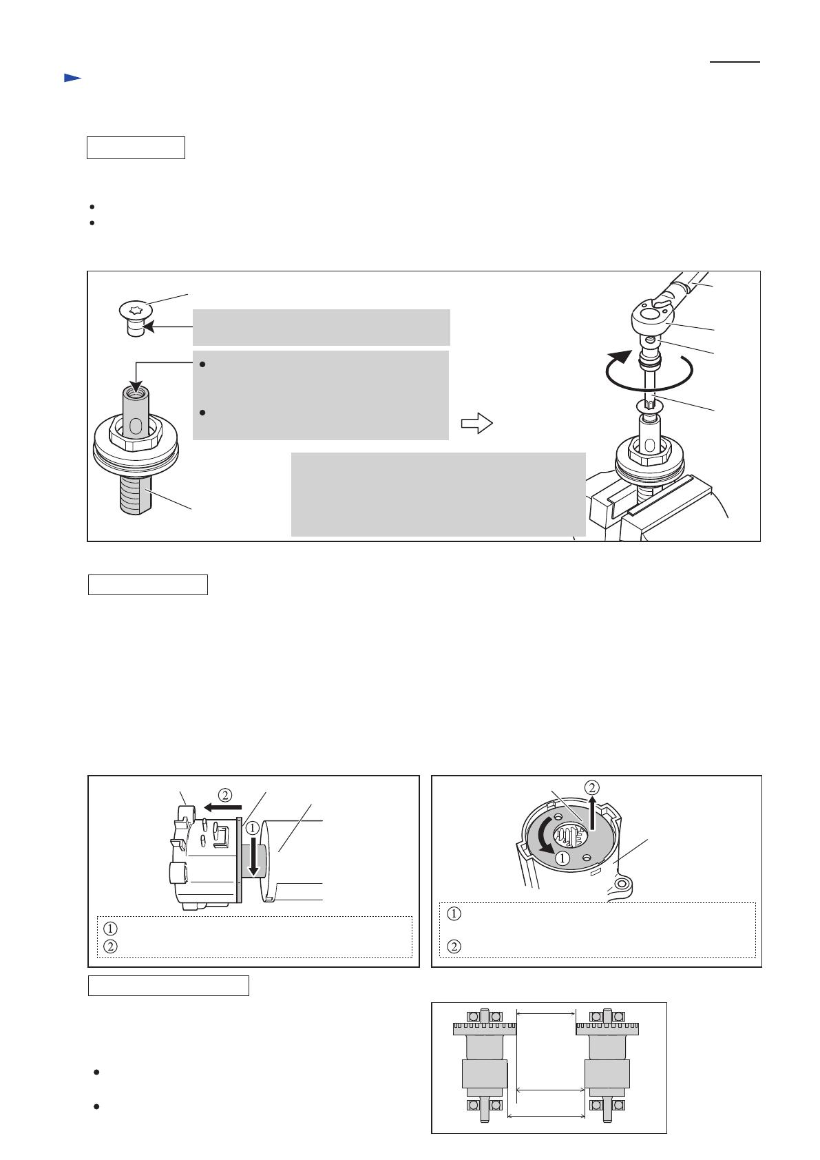
Fig. 23
Do the reverse of the disassembling steps.
ASSEMBLING
Note:
When fastening M5x10 Torx countersunk screw to Spindle, do as described in Fig. 23.
Apply Makita grease N. No.2 to all Steel balls and the Spindle's threaded portion for enaging with M12 Lock nut
before assembling. (Fig. 1) Be careful not to put the grease in the threaded hole of Spindle.
Spindle
M5x10 Torx countersunk head screw
Clean up this threaded portion with gasoline
or kerosene to remove oil or grease.
1R219
1R220
1R222
1R314
Fix Spindle in vise.
Then fasten M5x10 Torx countersunk head screw to
the recommended torque of 8-10N.m by turning
clockwise using 1R219, 1R220, 1R222 and 1R314.
Note: Wipe away any adhesive that might ooze out.
Clean up this threaded hole with gasoline
or kerosene to remove oil or grease from
the inner threaded portion.
Put about three drops of Loctite 603 in this
threaded hole.
[3] -5. Gear case section
DISASSEMBLING
1) Remove Light cover, Switch lever and Compression spring 2. See [3] -1 on page 5.
2) Remove four M4x22 Pan head screws to separate Angle head complete from the machine. (See [3] -3 on page 7.)
3) Remove seven M3x20 Pan head screws to separate Housing (L) from (R).
4) Remove Switch unit from Gear case section.
5) Separate Gear case section from Motor control unit by first lifting them up, then turning Motor bracket counterclockwise.
(Fig. 24)
6) Pull off Motor bracket from Rotor, and then pull off Rotor from Motor control unit.
7) Remove Lock washer located in Gear case by turning counterclockwise with pliers or slotted screwdriver. (Fig. 25)
8) Remove Spur gears, Internal gear 47, Carrier complete B and Ball bearing 6805LLB.
Fig. 25Fig. 24
Gear case section
Motor bracket
Lock washer
Turn Motor bracket counterclockwise, and then
Separate Gear case section from Motor control unit.
Turn Lock washer counterclockwise using pliers
or slotted screwdriver, and
Remove from Gear case section.
Gear case section
Motor control unit
Fig. 26
Caution for Handling Rotor
When handling or storing multiple Rotors, be sure to provide
the minimum distances specified in Fig. 26 between Rotors.
Rotor is a strongly magnetic body.
Therefore, failure to follow this instruction could result in:
Finger injury caused by pinching between Rotors pulling
each other
Magnetic loss of Rotors
10.0 mm
(3/8")
15.0 mm
(9/16")
19.9 mm(13/16")
P 8/ 13
Repair
[3] DISASSEMBLY/ASSEMBLY
[3] -5. Gear case section (cont.)
ASSEMBLING
1) After applying Makita grease N No.2 to teeth of all Spur gears, shafts of Carrier complete B and shafts of Spur gear 9
complete A, assemble Ball bearing 6805LLB and Carrier complete B to Gear case. (Fig. 2) Then assemble Internal gear
47 and Spur gears from the opposite side.
2) Install Rotor on Motor control unit as described below;
Fix Motor control unit on table or the like, and insert Rotor
slowly into Motor control unit until it touches the surface
of the table. Then lift up Motor control unit gradually
until it stops. (Fig. 26)
Caution:
1. Because Rotor is a strong magnet, be sure to remove metal chips
or debris from it before installation, be very careful not to pinch
your fingers between Rotor and metal parts, etc.
2. Be careful not to shock the printed wiring board of Motor
control unit.
3) Install Lock washer on Gear case, then put Motor bracket on
Gear case, and turn it clockwise to lock in place.
4) Assemble Gear case section and Motor control unit to Housing (R)
so that Lead wires of Motor control unit and the Switch unit
installation portion on Gear case faces the side of the LED - Trigger
switch line. (Fig. 27)
When assembling, fit the boss on Housing (R) in the notch in
Motor control unit. (Fig. 28)
5) Set Switch unit in place on Gear case.
6) Assemble the following parts to Housing (R) in numerical order:
1. Controller of Motor control unit
2. Terminal
3. LED circuit
4. Gear case section to which Motor control unit is assembled
Put Lead wires in place while taking care not to pinch them.
After putting Switch section in place, install Plate and Lens.
Then fasten Housing (L) to (R) with seven M3x20 Pan head screws.
(Fig. 29)
Caution: When disconnecting connectors, do not pull lead wires.
(Fig. 30)
Fig. 26
Fig. 27
Fig. 28
Fix Motor control unit, and insert Rotor.
Lift up Motor control unit until it stops.
Motor
control
unit
Housing (R)
notch
boss
Fig. 29
Fig. 30
Fix lead wires with
lead wire holders.
Fix lead wires with
Lead wire holders.
LED circuit
Switch unit
(ON/OFF)
Switch unit
for Clutch
Power supply circuit
Terminal
Color of Lead wires
Switch unit for
F/R change
Blue, Black
Yellow, White
Yellow, Blue
Purple, Yellow
Red, Black
Positive: Red
Negative: Black
Gear
case
Motor
control
unit
Switch unit installation portion
Lead wires
Cover
Plate
Lens
Terminal
Face the rib of Cover to
Terminal side and insert
the cover to Housing set.
rib of Cover
P 9/ 13
Repair
[3] DISASSEMBLY/ASSEMBLY
[3] -6. Switch section
DISASSEMBLING
M3x20 Pan head screw (7pcs.)
Housing set (R).
Fig. 31
(1) Remove Light cover, Compression spring 2 and Switch lever illustrated in Fig. 12.
(2) Separate Angle head complete from Housing set as illustrated in Fig. 13. However, no need to remove Clutch assembly.
(3) Remove Housing set (L) and seven M3x20 Pan head screws, and then remove Switch section as illustrated in Fig. 31.
Housing set (L)
Switch section
(4) Remove Switch unit in Trigger while expanding the ribs. (Fig. 32)
(5) Switch unit for rotation reverse can be replaced first by removing
PT3x16 T
apping scre
w, then removing Cover.
Now the following parts can also be replaced:
F/R Change lever, Leaf spring, Switch lever (A), Compression spring 4
Fig. 32
Fig. 33
Switch unit in Trigger
ribs
ASSEMBLING
(1) Put Leaf spring in place on F/R Change lever, and Compression spring 4
on Switch lever A.
(2) Put F/R Change lever, Switch lever and Switch unit for rotation reverse
in place; at this time, fit the protrusion on F/R Change lever in Switch
lever A. (Fig. 33)
Then, fasten the above parts with PT3x16 Tapping screw while holding
them with Cover.
protrusion on
F/R Change lever
Switch lever A
P 10/ 13
Fig. D-1
Circuit diagram
Stator
Controller
Terminal
Main switch
Switch unit B
(for rotation
reverse)
Switch unit A
(for Trigger)
Switch unit C
(for clutch)
LED
circuit
(for job
light)
LED circuit
(for display)
Power supply
circuit
= Tape
= Connector
Motor control unit
RF unit
Color index of lead wires' sheath
Black
White
Red
Orange
Gray
Blue
Yellow
Purple
P 11/ 13
Fig. D-2
Wiring diagram
Switch
Terminal
Power supply
circuit
Connector
rib (A)
Wiring around Controller
Receptacle
Terminal
Lead wire (black)
Lead wire (red)
Install Receptacles on Terminal as illustrated below.
Route Lead wires that connects Power supply circuit
with RF unit between three pins as illustrated below.
Sponge
Controller
boss
pin
Connector
rib (D)
rib (C)
rib (B)
groove
rib
Put Connectors and
the slack portion of
Lead wires in the space
between ribs (A)- (B)- (C)
and pins- rib (D)- boss.
Route Lead wires
(orange, white, blue)
from Controller to Stator
between the two pins.
Put Connector and Lead
wires from Controller to
Power supply circuit
between the ribs on
Controller.
Put Lead wires from Controller
to Power supply circuit on the
groove on Controller.
Put Power supply circuit
with Sponge on Housing (L) side.
Route Lead wires from
Switch unit (for Trigger)
between rib (B) and rib (C).
Route Lead wires from
Switch unit (for rotation
reverse) between rib (A)
and rib (C).
RF unit
pin
pin
P 12/ 13
Fig. D-3
Wiring diagram
[2] Wiring around Stator
Switch unit (for Clutch)
Lead wire holder
First, put the following Lead wires
from Controller in place:
*Lead wires to LED circuit
*Lead wires to Switch unit (for Clutch)
Then, fix Lead wires (orange, white, blue)
from Controller to Stator with this Lead
wire holder.
Route the following Lead wires from Controller
between rib (E) and the inside wall of Housing:
*Lead wires to LED circuit
*Lead wires to Switch unit (for Clutch)
At this time, place these Lead wires so that the
tape is positioned beside Printed wiring board.
pin
rib (G)rib (F)
rib (E)
Connector
Stator
Connector (to LED circuit)
Printed wiring board
tape
inside wall of Housing
Put Connectors and the slack
portion of Lead wires in the space
between rib (E) and the inside
wall of Housing.
Route six Lead wires (orange, black, white,
yellow, blue, red) from Controller to Stator
between rib (F) and rib (G).
Route three Lead wires
(orange, white, blue) from
Controller to Stator between
the pin and Stator.
P 13/ 13
Fig. 4
Wiring diagram
Wiring of Lead wires of LED circuit
Route Lead wires
under the two tabs.
rib
tab
tabs viewed from
left side
Put Connectors and the slack portion
of Lead wires in this space.
Note:
Be careful not to put Connectors or
the slack portion of Lead wires on
the ribs around LED circuit.
Route Lead wires between
these ribs.
Make sure that
Lead wires are tight
between this portion.
LED circuit
Light holder
Switch unit
Connector
  • Page 1 1
  • Page 2 2
  • Page 3 3
  • Page 4 4
  • Page 5 5
  • Page 6 6
  • Page 7 7
  • Page 8 8
  • Page 9 9
  • Page 10 10
  • Page 11 11
  • Page 12 12
  • Page 13 13

Makita BFL201F User manual

Category
Power tools
Type
User manual

Makita BFL201F is a cordless angle screwdriver designed for fastening works, particularly in assembly lines. It features a powerful 14.4V/3.0Ah Li-ion battery and a BLDC motor for efficient operation. The screwdriver offers precise torque control with a range of 8 - 20 N.m and a no-load speed of 360 rpm. It comes with a standard square 9.5 (3/8) driving shank, soft start, LED job light, electric brake, reversing switch, and torque adjustment. The BFL201F is well-suited for various applications, including carpentry, metalworking, and automotive assembly.

Ask a question and I''ll find the answer in the document

Finding information in a document is now easier with AI