Specification
Standard equipment
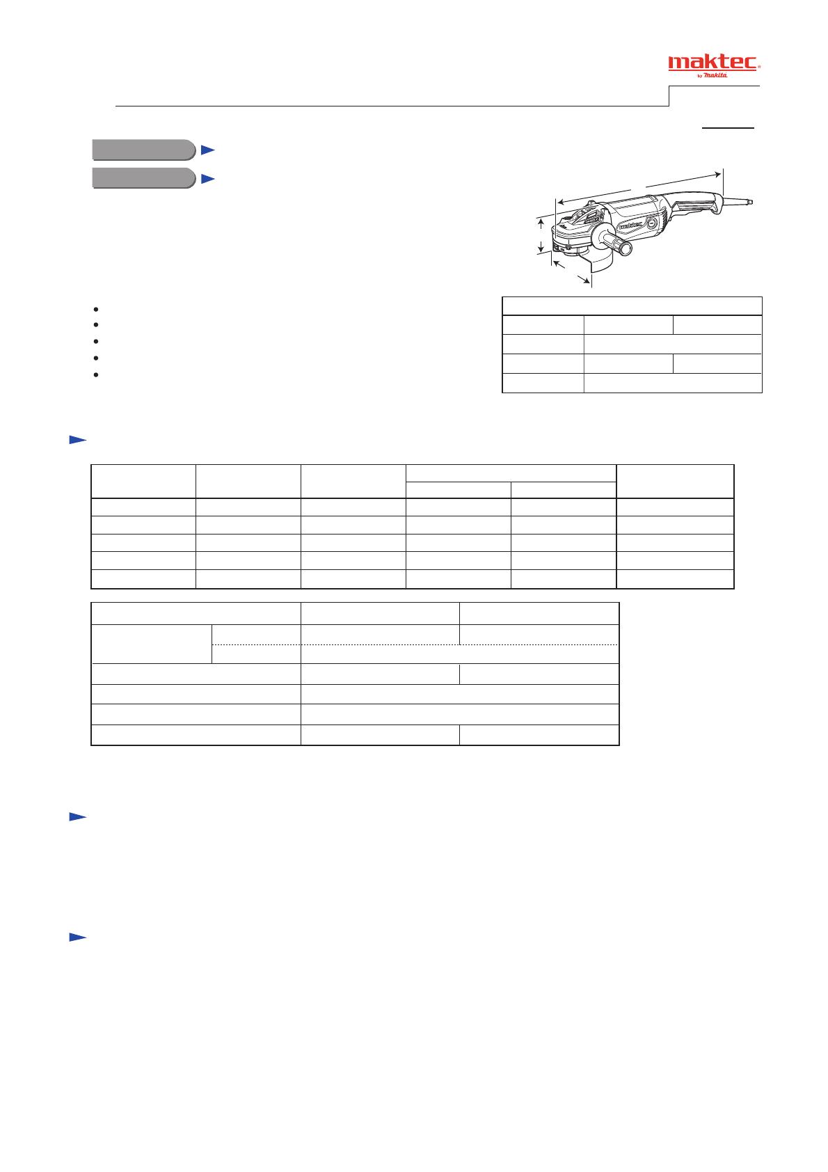
Dimensions: mm (")
Width (W)
Height (H)
Length (L)
Model No.
MT902 MT903
466 (18-3/8)
200 (7-7/8) 250 (9-7/8)
138 (5-7/16)
Note: The standard equipment for the tool shown above may vary by country.
Models MT902 and MT903 have been developed as the aesthetic
change models of maktec angle grinders MT900 and MT901.
Feature the same advantages the current models as follows:
Anti-dust, heavy-duty 2,000W motor
Industrial performance and durability at less expense
High dust-proof construction
Rear handle with anti-slip surface for more control
Machined spiral bevel gear for durability and long
service life of the machine
Lock nut wrench ................ 1 pc.
Side grip ............................. 1 pc.
Model No.
No load speed: min.
-1 = rpm
Diameter
Hole diameter
Wheel size: mm (")
Protection against electric shock
Power supply cord: m (ft)
Net weight*: kg (lbs)
MT902 MT903
180 (7) 230 (9)
2.0 (6.6)
5.4 (12.0) 5.7 (12.6)
8,500 6,600
Double insulation
22.23 (7/8)
Continuous Rating (W)
Voltage (V) Cycle (Hz)
Input Output
Max. Output (W)
120
110 15 1,650
---
1,100 2,70050/60
9.6 2,000 1,400 3,00050/60
8.8 2,000 1,400 3,00050/60
15 1,100 2,70050/60
220
9.2 2,000 1,400 3,00050/60230
240
Current (A)
Optional accessories
MT902: Accessories for 180mm angle grinder
MT903: Accessories for 230mm angle grinder
* Weight according to EPTA-Procedure 01/2003, with Side grip, Wheel cover, Inner flange, Lock nut
Model No.
Description
MT902, MT903
Angle Grinders 180mm (7")/ 230mm (9")
CONCEPT AND MAIN APPLICATIONS
L
H
W
P 1/ 9
PRODUCT
T
ECHNICAL INFORMATION


