
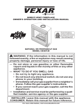
DIRECT-VENT FIREPLACE
OWNER’S OPERATION AND INSTALLATION MANUAL
For more information, visit www.desatech.com
NATURAL GAS “TUDOR” MODELS (V)T32EN-A SERIES
PROPANE/LP GAS “TUDOR” MODELS (V)T32EP-A SERIES
WARNING: If the information in this manual is not fol-
lowed exactly, a re or explosion may result causing
property damage, personal injury or loss of life.
— Do not store or use gasoline or other ammable
vapors and liquids in the vicinity of this or any other
appliance.
— WHAT TO DO IF YOU SMELL GAS
• Do not try to light any appliance.
• Do not touch any electrical switch; do not use any
phone in your building.
• Immediately call your gas supplier from a neighbor’s
phone. Follow the gas supplier’s instructions.
• If you cannot reach your gas supplier, call the re
department.
— Installation and service must be performed by a quali-
ed installer, service agency or the gas supplier.
INSTALLER: Leave this manual with the appliance.
CONSUMER: Retain this manual for future reference.

www.desatech.com
116647-01D2
SAFETY INFORMATION
TABLE OF CONTENTS
Safety Information ............................................... 2
Local Codes......................................................... 4
Product Identication ........................................... 4
Product Features ................................................. 4
Pre-Installation Preparation ................................. 5
Location of Termination Cap ................................ 7
Venting Installation Instructions ........................... 8
Fireplace Installation.......................................... 17
Wiring Diagram .................................................. 26
Operating Fireplace ........................................... 26
Inspecting Burners............................................. 28
Cleaning and Maintenance ................................ 28
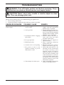
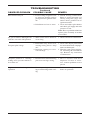
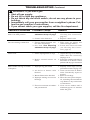
Troubleshooting ................................................. 30
Replacement Parts ............................................ 33
Service Hints ..................................................... 33
Technical Service............................................... 33
Specications .................................................... 33
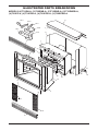
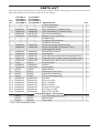
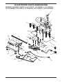
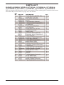
Illustrated Parts Breakdown and Parts List........ 34
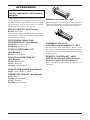
Accessories ....................................................... 38
Warranty Information ...........................Back Cover
WARNING: Improper in-
stallation, adjustment, al-
teration, service or main-
tenance can cause in-
jury or property damage.
Refer to this manual for
correct installation and
operational procedures.
For assistance or addi-
tional information con-
sult a qualied installer,
service agency or the gas
supplier.
This appliance may be in-
stalled in an aftermarket,*
permanently located,
manufactured (mobile)
home, where not prohib-
ited by local codes.
This appliance is only for
use with the type of gas
indicated on the rating
plate. This appliance is
not convertible for use
with other gases, unless
a certied kit is used.
* Aftermarket: Completion of sale, not for
purpose of resale, from the manufacturer
State of Massachusetts:
The installation must
be made by a licensed
plumber or gas tter in
the Commonwealth of
Massachusetts.
WARNING: This product
contains and/or generates
chemicals known to the State
of California to cause cancer or
birth defects or other reproduc-
tive harm.
IMPORTANT: Read this owner’s
manual carefully and completely
before trying to assemble, op-
erate or service this replace.
IMPORTANT: Read this owner’s
manual carefully and completely
before trying to assemble, op-
erate or service this replace.
Improper use of this replace
can cause serious injury or death
from burns, re, explosions,
electrical shock and carbon
monoxide poisoning.
DANGER: Carbon monoxide
poisoning may lead to death!

www.desatech.com
116647-01D 3
This replace must be installed by a qualied (cer-
tied or licensed) service person. It has a sealed
gas combustion chamber that uses a coaxial pipe
(pipe within a pipe and having the same center)
venting system. It brings in fresh air for combus-
tion through the outer pipe and combustion gases
are exhausted through the inner pipe. If the glass
door assembly and venting pipe are not properly
seated, connected and sealed, carbon monoxide
leakage (spillage) can occur.
Carbon Monoxide Poisoning: Early signs of carbon
monoxide poisoning resemble the u, with head-
aches, dizziness or nausea. If you have these signs,
the replace may not be working properly. Get
fresh air at once! Have replace serviced. Some
people are more affected by carbon monoxide than
others. These include pregnant women, people with
heart or lung disease or anemia, those under the
inuence of alcohol and those at high altitudes.
Natural and Propane/LP Gas: Natural and pro-
pane/LP gases are odorless. An odor-making agent
is added to the gas. The odor helps you detect a gas
leak. However, the odor added to the gas can fade.
Gas may be present even though no odor exists.
Make certain you read and understand all warnings.
Keep this manual for reference. It is your guide to
safe and proper operation of this replace.
WARNING: Any change to
this replace or its controls can
be dangerous.
WARNING: Do not use a blow-
er insert, heat exchanger insert
or other accessory not approved
for use with this replace.
Do not use any solid fuels (wood,
coal, paper, cardboard, etc.) in
this replace. Use only the gas
type indicated on replace name
plate.
Carefully supervise young chil-
dren when they are in the room
with replace.
SAFETY INFORMATION
Continued
This replace reaches high tem-
peratures. Keep children and
adults away from hot surfaces to
avoid burns or clothing ignition.
Fireplace will remain hot for a
time after shutdown. Allow sur-
faces to cool before touching.
Do not operate replace with
glass door removed, cracked
or broken.
Keep the appliance area clear
and free from combustible ma-
terials, gasoline and other am-
mable vapors and liquids.
Do not place clothing or other
ammable material on or near
replace. Never place any ob-
jects on replace.
1. This appliance is only for use with the type
of gas indicated on the rating plate. This ap-
pliance is not convertible for use with other
gases unless a certied kit is used.
2. For propane/LP replace, do not place pro-
pane/LP supply tank(s) inside any structure.
Locate propane/LP supply tank(s) outdoors.
To prevent performance problems, do not
use propane/LP fuel tank of less than 100 lb.
capacity.
3. If you smell gas
• shut off gas supply
• do not try to light any appliance
• do not touch any electrical switch; do not use
any phone in your building
• immediately call your gas supplier from a
neighbor’s phone. Follow the gas supplier’s
instructions
• if you cannot reach your gas supplier, call
the re department
4. Never install the replace
• in a recreational vehicle
• in windy or drafty areas where curtains or
other combustible (ammable) objects can
make contact with the replace front
• in high trafc areas
5. Do not modify this replace under any circum-
stances. Any parts removed for servicing must
be replaced prior to operating replace.

www.desatech.com
116647-01D4
SAFETY INFORMATION
Continued
6. Turn replace off and let cool before servicing,
installing or repairing. Only a qualied service
person should install, service or repair this
replace. Have replace inspected annually
by a qualied service person.
7. You must keep control compartments, burn-
ers and circulating air passages clean. More
frequent cleaning may be needed due to ex-
cessive lint and dust from carpeting, bedding
material, etc. Turn off the gas valve and pilot
light before cleaning replace.
8. Have venting system inspected annually by a
qualied service person. If needed, have vent-
ing system cleaned or repaired. See Cleaning
and Maintenance, page 28.
9. Do not use this replace to cook food or burn
paper or other objects.
10. This appliance, when installed, must be electri-
cally grounded in accordance with local codes
or, in the absence of local codes, with the
National Electrical Code, ANSI/NFPA 70 or
the Canadian Electrical Code, CSA C22.1.
11. Do not use replace if any part has been under
water. Immediately call a qualied service per-
son to arrange for replacement of the unit.
12. Do not operate replace if log is broken.
13. Provide adequate clearances around air
openings.
LOCAL CODES
Install and use replace with care. Follow all local
codes. In the absence to local codes, use the cur-
rent National Fuel Gas Code ANSI Z223.1/NFPA
54* (USA) or the current CSA-B149.1 Installation
Code (Canada).
*Available from:
American National Standards Institute, Inc.
1430 Broadway
New York, NY 10018
National Fire Protection Association, Inc.
Batterymarch Park
Quincy, MA 02269
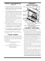
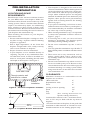
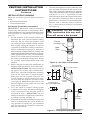
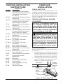
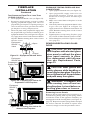
Figure 1 - Direct-Vent Fireplace with
Electronic Ignition
Glass Door Assembly
Switch Bracket for Optional
Remote and Blower
Electronic
Control Valve
Log
Set
Lava
Rock
Glowing
Embers
Upper Louver Panel
Lower
Louver
Panel
Flue Collar
Nailing
Flange
Burner Assembly
PRODUCT FEATURES
These are a few facts that can help you understand
and enjoy your direct-vent replace:
• The venting system may be routed to the outside
of your home in several ways. It may vent through
the roof (vertical) or it may vent to an outside/exte-
rior wall (horizontal). The vent pipe installation is
very important to allow for proper operation. You
must follow the venting instructions very carefully
for either vertical or horizontal applications.
• This replace may be installed in any room of
your house provided all local codes and these
installation instructions are followed.
• The blower requires electricity if installed. If
you plan to install the blower at a later date,
outlet must be wired at the bottom of the re-
place when framing.
• The electronic ignition creates spark to ignite
the pilot light. It does not require any matches,
batteries or any other sources of ignition to light
the pilot.
• Each time you turn on your replace, you may
notice some amount of condensation on the in-
side of the replace glass. This is normal and will
disappear after 10-20 minutes of operation.
•
Your direct-vent gas replace system (replace
and venting) is a balanced and sealed gas operating
unit. It requires approximately 10-20 minutes of
operating time before the ame pattern stabilizes.
PRODUCT
IDENTIFICATION

www.desatech.com
116647-01D 5
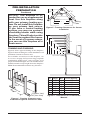
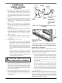
Figure 2 - Common Fireplace Locations
Flush with a wall
Through exterior wall
enclosed in a chase
Corner
installation
Figure 3 - Fireplace Bottom Dimensions
D
RW
FW
22
1
/
2
"
16
5
/8"
34
3
/
8
"
PRE-INSTALLATION
PREPARATION
LOCATION AND SpACE
REqUIREMENTS
Determine the safest and most efcient location
for your DESA direct-vent replace. Make sure
that rafters and wall studs are not in the way of the
venting system. Choose a location where the heat
output is not affected by drafts, air conditioning
ducts, windows or doors. Figure 2 shows some
common locations. Be aware of all restrictions and
precautions before deciding the exact location for
your replace and termination cap.
When deciding the location of your replace,
follow these rules:
• Do not connect this replace venting to a chim-
ney ue serving a separate solid-fuel burning
replace or appliance.
• Due to high temperatures, do not locate this
replace in high trafc areas, windy or drafty
areas or near furniture or draperies.
• Proper clearances must be maintained.
• If your replace is to be installed directly on
carpeting, vinyl tile or any combustible mate-
rial other than wood, it must be installed on a
metal or wood panel extending the full width
and depth of the replace. See Figure 3.
• Your replace is designed to be used in zero
clearance installations. Wall or framing material
can be placed directly against any exterior sur-
face on the back, sides or top of your replace,
except where standoff spacers are integrally
attached. If standoff spacers are attached to your
replace, these spacers can be placed directly
against wall or framing material. See framing
details on page 6.
• If you plan on installing a television or enter-
tainment center recessed above your replace, it
is recommended that you maintain a minimum
18" above top of louver opening.
• When locating termination cap, it is important
to observe the minimum clearances shown in
Figure 7, page 7.
• If recessing into a wall, you can avoid extra
framing by positioning your replace against
an already existing framing member.
• Do not recess termination cap into a wall or
siding.
• You may paint the termination cap with 450º F
heat-resistant paint to coordinate with the exterior
nish.
• There must not be any obstruction such as
bushes, garden sheds, fences, decks or util-
ity buildings within 24" from the front of the
termination cap.
• Do not locate termination cap where excessive
snow or ice build up may occur. Be sure to clear
vent termination area after snow falls to prevent
accidental blockage of venting system. When
using snow blowers, do not direct snow towards
vent termination area.
CLEARANCES
Minimum clearances to combustibles for the
replace are as follows:
*Back and sides 0"
Perpendicular walls 6"
Floor 0"
Ceiling to louver opening 42"
Front 36"
Top 0"
Vent (See venting instructions for
specic venting clearances.)
Combustible material with a maximum thick-
ness of 5/8" may be ush with the top front of
replace.
* For back and sides of replace, do not pack with
insulation or other materials. 0" clearance to com-
bustible materials are for framing purpose only.

www.desatech.com
116647-01D6
PRE-INSTALLATION
PREPARATION
Continued
NOTICE: This replace is in-
tended for use as supplemental
heat. Use this replace along
with your primary heating sys-
tem. Do not install this replace
as your primary heat source.
If you have a central heating
system, you may run system’s
circulating blower while using
replace. This will help circulate
the heat throughout the house.
In the event of a power outage,
you can use this replace as a
heat source.
FRAMING AND FINISHING
Figure 4 shows typical framing of this replace.
Figure 5 shows framing for corner installation. All
minimum clearances must be met.
For available accessories for this replace, see
Accessories on page 38. If you are using a separate
combustible mantel piece, refer to Figure 6 for
proper installation height. You can install noncom-
bustible mantels at any height above the replace.
Note: Noncombustible mantels may discolor!
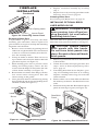
Figure 4 - Framing Clearances for
Installation Against an Exterior Wall
32
3
/8"
34
5
/8"
17" (Horiz. Vent)
20" (Vert. Vent)
Figure 5 - Framing Clearances for Corner
Installation
A
B
E
F
G
H
D
C
Nailing Tabs
28
1
/2"
13
5
/
8
"
39
3
/8"
10
3
/8"
9
7
/8"
34
3
/8"
34
5
/8"
54
1
/8"
Nailing
Tabs
C
B
A
D
E
F
G
Top of Louver Opening
3
2
1
4
5
6
7
Wall
Figure 6 - Clearances for Combustible
Mantels
Ref.
Mantel
Depth Ref.
Mantel from Top of
Louver Opening
1 14" A 16"
2 12" B 14"
3 10" C 12"
4 8" D 10"
5 6" E 8"
6 4" F 6"
7 2" G 4"

www.desatech.com
116647-01D 7
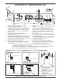
Figure 7 - Minimum Clearances for Termination Cap
LOCATION OF TERMINATION CAP
Fixed
Closed
Openable
Fixed
Closed
V
V
V
V
V
V
V
V
X
X
V
X
G
G
J
F
B
B
K
N
H
I
A
N
E
L
D
B
M
A
C
B
V
V
A
G
G
B
TERMINATION CAP
AIR SUPPLY INLET
GAS METER RESTRICTED AREA
(TERMINATION PROHIBITED)
A = clearance above grade, veranda, porch, deck, or
balcony [*12" (30.5 cm) minimum]
B = clearance to window or door that may be opened
[6" (15 cm) min. for 10,000 Btu or less; 9" (23 cm) in US
if between 10,000 and 50,000, 12" (30 cm) in Canada
if between 10,000 and 100,000; 12" (30 cm) in US if
greater than 50,000, 36" (91 cm) in Canada if greater
than 100,000]
C = clearance to permanently closed window
[minimum 12" (30.5 cm) recommended to prevent
condensation on window]
D = vertical clearance to ventilated soffit located above the
terminal within a horizontal distance of 24" (61 cm) from
the center-line of the terminal [18" (45.7 cm) minimum]
E = clearance to unventilated soffit [12" (30.5 cm) minimum]
F = clearance to outside corner (see below)
G = clearance to inside corner (see below)
H = *not to be installed above a meter/regulator assembly
within 36" (91.4 cm) horizontally from the center line
of the regulator
I = clearance to service regulator vent outlet [*72" (182.9 cm)
minimum]
J = clearance to non-mechanical air supply inlet to building
or the combustion air inlet to any other fireplace
[6" (15 cm) min. for 10,000 Btu or less; 9" (23 cm) in US
if between 10,000 and 50,000, 12" (30 cm) in Canada
if between 10,000 and 100,000; 12" (30 cm) in US if
greater than 50,000, 36" (91 cm) in Canada if greater
than 100,000]
K = clearance to a mechanical air supply inlet [*In Canada,
6 ft. (1.83m) minimum; In US 3 ft. (91 cm) above if within
10 ft. (3 m) horizontally]
L = † clearance above paved side-walk or a paved driveway
located on public property [*84" (213.3 cm) minimum]
M = clearance under veranda, porch, deck
[*12" (30.5 cm) minimum ‡]
N = clearance above a roof shall extend a minimum of
24" (61 cm) above the highest point when it passes
through the roof surface and any other obstruction within
a horizontal distance of 18" (45.7 cm)
† vent shall not terminate directly above a side-walk or paved driveway which is located between two
single family dwellings and serves both dwellings*
‡ only permitted if veranda, porch, deck or balconey is fully open on a minimum of 2 sides beneath the floor*
* as specified in CAN/CSA B149 (.1 or .2) Installation Codes (1991) for Canada and U.S.A.
Note: Local codes or regulations may require different clearances
A = 6" (15.2 cm)
Inside Corner
V
B
E
V
B = 6" (15.2 cm)
C = Maximum depth of 48" (121.9 cm)
for recessed location
D = Minimum width for back wall of
recessed location -
Combustible - 38" (965 mm)
Noncombustible - 24" (61 cm)
E = Clearance from corner in
recessed location-
Combustible - 6" (15.2 cm)
Noncombustible - 2" (5.1 cm)
Outside Corner Recessed Location
G
H
G = 12" (30.5 cm) minimum clearance
Balcony with No Side Wall
V
J
Combustible &
Noncombustible
H = 24" (61 cm)
J = 20" (50.8 cm)
Balcony with Perpendicular Side Wall
C
D
C
Termination Clearances for Buildings with Combustible and Noncombustible Exteriors
Openable

www.desatech.com
116647-01D8
VENTING INSTALLATION
INSTRUCTIONS
NOTICE: Read these instruc-
tions completely before at-
tempting installation.
These models are tested and approved for use
with DESA (direct-vent) pipe components and
terminations.
The venting system must terminate on the outside of
the structure and can not be attached to a chimney
or ue system serving a separate solid fuel or gas
burning appliance. A direct-vent appliance must
have its own venting system. DO NOT common
vent this appliance.
These models are approved to be vented either
horizontally through an outside wall or vertically
through a roof or chase enclosure using the fol-
lowing guidelines:
• When venting system terminates horizontally
on an outside wall, you may install a standoff
if the termination cap is to be installed directly
on a combustible nish such as vinyl, wood,
stucco, etc.
• Never run the vent downward as this may
cause excessive temperatures which could
cause a re.
• Vent pipe air space clearances to combustibles
are 1" on all sides except on the horizontal
sections, which requires 2" clearance from
the top of the pipe. Where the termination cap
penetrates a combustible wall, 1" air space
clearance is required.
• Snorkel terminations are required when minimum
clearance to grade cannot be met (see Figure 16
on page 12).
• Have replace and selected vent components on
hand to help determine the exact measurements
when elbowing or offsetting. Always use wall
restops when penetrating walls and restops
when penetrating ceilings or attic spaces.
• If using a venting conguration of only hori-
zontal venting with no vertical run, a 1/4" rise
for every 12" of run toward the termination is
required.
WARNING: Read all instruc-
tions completely and thoroughly
before attempting installation.
Failure to do so could result in
serious injury, property damage
or loss of life.
NOTICE: Failure to follow these in-
structions will void the warranty.
IMPORTANT: Do not seal vent cap to pipe. Cap
must be removable for service.
INSTALLATION pRECAUTIONS
• Wear gloves and safety glasses for protection
• Use extreme caution when using ladders or when
on roof tops
• Be aware of electrical wiring locations in walls
and ceilings
The following actions will void the warranty on
your venting system:
•
Installation of any damaged venting com-
ponent
• Unauthorized modication of the venting system
(Do not cut or alter vent components)
• Installation of any component part not manu-
factured or approved by DESA
• Installation other than as instructed by these
instructions
WARNING: This gas replace
and vent assembly must be
vented directly to the outside.
The venting system must NEVER
be attached to a chimney serv-
ing a separate solid fuel burning
appliance. Each direct-vent gas
appliance must use a separate
vent system. Do not use com-
mon vent systems.
WARNING: Vent pipe air
space clearances to combustibles
are 1" on all sides except on the
horizontal sections, which require
2" clearances from the top of the
pipe. Where the termination cap
penetrates a combustible wall, 1"
air space clearance is required.

www.desatech.com
116647-01D 9
INSTALLATION pLANNING
There are two basic types of direct-vent instal-
lation:
• Horizontal Termination
• Vertical Termination
Horizontal Termination Installation
IMPORTANT: Horizontal square terminations
require only inner portion of wall restop. Hori-
zontal installations using round termination require
exterior portion of wall restop (see Figure 14,
page 11).
1. Set the replace in its desired location and
determine the route your horizontal venting
will take. Do not secure the replace until
all venting has been installed. Some installa-
tions require sliding the replace in and out
of position to make nal venting connections.
Figures 14 through 18 on pages 11 through 13
show different congurations for venting with
horizontal termination that will help you decide
which application best suits your installation.
Check to see if wall studs or roof rafters are in
the path of your desired venting route. If they
are, you may want to adjust the location of the
replace.
2. Direct vent pipe sections and components are
designed with special twist-lock connections.
Twist-Lock procedure: The female ends of
the pipes have locking lugs (indentations).
These lugs will slide straight into matching
slots on the male ends of adjacent pipes.
Push pipe sections together and twist one
section clockwise approximately one-quar-
ter turn until the sections are fully locked
(see Figure 8). Note: Horizontal runs of vent
must be supported every three feet. Use wall
straps for this purpose.
3. Use a 45° elbow to connect venting system
to replace ue collar. The elbow is designed
to be twist-locked onto the flue collar as
described in step 2. IMPORTANT: Do not
attempt to alter the conguration of the elbow
by cutting, twisting, bending, etc.
4. Assemble the desired combination of pipe and
elbows to the replace ue collar. If there are
long portions of venting run, pre-assembled
pipe sections may be installed as subassem-
blies for convenience.
VENTING INSTALLATION
INSTRUCTIONS
Continued
5. Carefully determine the location where the vent
pipe assembly will penetrate the outside wall.
The center of the hole should line up with the
center-line of the horizontal vent pipe. Mark the
wall for a 11
1
/
2
" x 11
1
/
2
" square hole. Cut and
frame the square hole in the exterior wall where
the vent will be terminated. If the wall being
penetrated is constructed of noncombustible
material, such as masonry block or concrete,
a 8
1
/2" hole with zero clearance is acceptable
(see Figure 9).
WARNING: Do not recess
vent termination into any wall.
This will cause a re hazard.
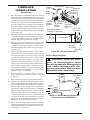
Figure 8 - Vent Pipe Connections
Female
Locking Lugs
Male
Slots
(Framing
Detail)
11
1
/
2
"
11
1
/
2
" Inside Framing
11
1
/
2
"
8
1
/
2
"
Vent
O
pening
Combustible Wall
Vent Opening
Noncombustible Wall
Figure 9 - Vent Opening Requirements
Center
of Hole

www.desatech.com
116647-01D10
6. Noncombustible Exterior Wall: Position the
horizontal vent cap in the center of the 8
1
/
2
"
round hole and attach to the exterior wall with
four screws. Note: The four wood screws
provided should be replaced with appropriate
fasteners for stucco, brick, concrete or other
types of sidings. Before attaching the vent cap
to exterior wall, run a bead of non-hardening
mastic (pliable sealant) around the outside edges
to make a seal between it and the outside wall.
Combustible Exterior Wall: For vinyl siding,
stucco or wood exteriors, a siding standoff
may be installed between the vent cap and
exterior wall. The siding standoff prevents
excessive heat from damaging the siding
materials. Siding material must be cut to
accommodate standoff. Bolt the vent cap to
the standoff. Apply non-hardening mastic
around outside edge of standoff. Position the
standoff/cap assembly in the center of the
11
1
/
2
" square hole and attach to exterior wall
with wood screws provided (see Figure 11).
The siding standoff must sit ush against the
exterior fascia material.
7. Combustible Exterior Wall Only: Slide the wall
restop over the vent pipe before connecting
horizontal run to vent cap (see Figure 12).
8. Carefully move replace, with vent assembly
attached, toward wall and insert vent pipe
into horizontal termination. The pipe overlap
should be a minimum of 1
1
/
4
" (see Figure 13,
page 11).
9. Combustible Exterior Wall Only: Slide wall
restop against interior wall surface and attach
with screws provided (see Figure 12). See
Figure 13, page 11 for horizontal termination
details.
VENTING INSTALLATION
INSTRUCTIONS
Continued
Figure 10 - Installing Horizontal Vent Cap
(Noncombustible Exterior)
Figure 11 - Installing Siding Standoff
(Combustible Exterior)
Wood
Screw
Vent
Cap
Cut Siding Away to
Fit Standoff
Wood Screw
Screws
Standoff
Vent Cap
Apply Mastic
to All Four Sides
10. Place replace into position and shim with
noncombustible material if needed. Nail or
screw side anges to framing to secure unit in
place. IMPORTANT: Make sure replace is
level before securing. If replace is not level
it will not work properly.
Vent Cap
(Horizontal
Termination)
Interior Wall
Surface
Wall
Firestop
Horizontal
Vent Pipe
Figure 12 - Connecting Vent Cap with
Horizontal Vent Pipe
Screw
Apply Mastic
to All Four Sides

www.desatech.com
116647-01D 11
Figure 13 - Typical Horizontal
Termination Cap Mounting with
Additional Siding Standoff Installed
Siding
Standoff
Screws
High Wind
Termination
Apply
Mastic to
Outside
Edge of
Standoff
Exterior Wall
with Vinyl
Siding
10
3
/4" x 10
3
/4"
Framed
Opening
Maintain 1"
Minimum Air
Space Around
Outer Pipe When
Penetrating a
Wall
Minimum Pipe
Overlap 1
1
/4"
Wall
Firestop
Direct
Vent
Pipe
VENTING INSTALLATION
INSTRUCTIONS
Continued
Horizontal Termination Congurations
Figures 14 through 18 show different congura-
tions and alternatives for venting with horizontal
termination. Each gure includes a chart with
critical minimum and maximum dimensions which
MUST be met. IMPORTANT: If using a venting
conguration of only horizontal venting with no
vertical run, a 1/4" rise for every 12" of run toward
the termination is required.
WARNING: Never run vent
downward as this may cause
excessive temperatures which
could cause a re. Operation of
improperly installed and main-
tained venting system could
result in serious injury, property
damage or loss of life.
Vertical (V) Horizontal (H)
29
3
/
4
" 17" max.
Horizontal High
Wind Square
Termination
Wall
Firestop
45° Elbow
Figure 14 - Horizontal Termination
Conguration for Square or Round
Termination
45° Elbow
Wall
Firestop
Horizontal
Round
Termination
Exterior
Portion of Wall
Firestop (Round
Termination Only)
GROUND FLOOR INSTALLATION
Recommended Applications:
• Installation using cabinet surrounds
• Through the wall using round or square termina-
tion (up to 12" horizontal pipe)
• NOT FOR CORNER INSTALLATION
Adjustable
Pipe 12"
Max.
Square Termination

www.desatech.com
116647-01D12
VENTING INSTALLATION INSTRUCTIONS
Continued
Vertical (V) Required
Vertical (V) Vertical Pipe Horizontal (H)
*43
3
/
4
" min. None 30" max.
53
3
/
4
" min. 1 ft. 48" max.
65
3
/
4
" min. 2 ft. 60" max.
77
3
/
4
" min. 3 ft. 84" max.
89
3
/
4
" min. 4 ft. 20' max.
* Ground Floor Corner Venting
Figure 15 - Horizontal Termination Conguration for Corner Installation Using One
90° Elbow
Square
Termination
Wall
Firestop
Not to Exceed
(H) Limits
As Required
for (V), See
Chart for
Pipe Section
Required
45°
Elbow
90° Elbow
90°
Elbow
Square
Termination
Wall
Firestop
45°
Elbow
Not to Exceed
(H) Limits
12" Min.
CORNER INSTALLATION
Recommended Applications:
• Corner ground oor installation
• Ground oor installation where pipe vents horizontally through wall (over 12" horizontal pipe)
• Basement installation where one foot clearance from ground to termination is possible
SNORKEL TERMINATION INSTALLATION
Recommended Applications:
• Installations requiring a vertical rise on building
exterior
• Any installation using snorkel termination to
achieve one foot above ground
Snorkel
Termination
12" Min.
12" Min.
Adequate
Drainage
Snorkel
Termination
Snorkel
Termination
90° Elbow
12" Min.
Wall
Firestop
Snorkel terminations are available for installations
requiring a vertical rise on the exterior of the build-
ing. If installing snorkel termination below grade,
you must provide proper drainage to prevent water
from entering snorkel termination (see Figure 16).
Do not back ll around snorkel termination.
Figure 16 - Snorkel Termination Congurations for Below Ground Installation

www.desatech.com
116647-01D 13
HORIZONTAL SYSTEM INSTALLATION USING TWO 90° ELBOWS
The following congurations show the minimum vertical rise requirements for a horizontal system
using two 90° elbows.
VENTING INSTALLATION INSTRUCTIONS
Continued
Figure 17 - Horizontal Termination Conguration for Venting Using Two 90° Elbows
Venting with Two 90° Elbows
Horizontal (H
1
) +
Vertical (V) Horizontal (H
1
) Horizontal (H
2
)
5' min. 2' max. 6' max.
6' min. 4' max. 12' max.
7' min. 6' max. 18' max.
8' min. 8' max. 20' max.
20' max. 8' max. 20' max.
45° Elbow
Figure 18 - Horizontal Termination Conguration for Venting Using Two 90° Elbows
with Termination at 90° with Fireplace
Venting with Two 90° Elbows
Horizontal (H
1
) +
Vertical (V) Horizontal (H
2
)
5' min. 6' max.
6' min. 12' max.
7' min. 18' max.
8' min. 20' max.
20' max. 20' max.
45° Elbow

www.desatech.com
116647-01D14
INSTALLATION FOR VERTICAL
TERMINATION
Note: Vertical restrictor must be installed in all
vertical installations.
1. Determine the route your vertical venting
will take. If ceiling joists, roof rafters or other
framing will obstruct the venting system,
consider an offset (see Figure 19) to avoid cut-
ting load bearing members. Note: Pay special
attention to these installation instructions for
required clearances (air space) to combustibles
when passing through ceilings, walls, roofs,
enclosures, attic rafters, etc. Do not pack air
spaces with insulation. Also note maximum
vertical rise of the venting system and any
maximum horizontal offset limitations.
2. Set the replace in desired location. Drop a
plumb line down from the ceiling to the posi-
tion of the replace exit ue. Mark the center
point where the vent will penetrate the ceiling.
Drill a small locating hole at this point.
Drop a plumb line from the inside of the roof
to the locating hole in the ceiling. Mark the
center point where the vent will penetrate the
roof. Drill a small locating hole at this point.
Flat Ceiling Installation
1. Cut a 11
1
/
2
" square hole in the ceiling using
the locating hole as a center point. The open-
ing should be framed to 11
1
/
2
" x 11
1
/
2
" inside
dimensions, as shown in Figure 9 on page 8
using framing lumber the same size as the
ceiling joists. If the area above the ceiling is
an insulated ceiling or an attic, nail restop
from the top side. This prevents loose insula-
tion from falling into the required clearance
space. If the area above the ceiling is a living
space, install restop below the framed hole.
The restop should be installed with no less
than three nails per side (see Figure 20).
2. Assemble the desired lengths of pipe and
elbows necessary to reach from the replace
ue up through the restop. Be sure all pipe
and elbow connections are fully twist-locked
(see Figure 8, page 9).
3. Cut a hole in the roof using the locating hole
as a center point. (Cover any exposed open
vent pipes before cutting hole in roof.) The
11
1
/
2
" x 11
1
/
2
" hole must be measured on
the horizontal; actual length may be larger
depending on the pitch of the roof. There
must be a 1" clearance from the vent pipe to
combustible materials. Frame the opening as
shown in Figure 9, page 9.
4. Connect a section of pipe and extend up
through the hole.
Note: If an offset is needed to avoid obstruc-
tions, you must support the vent pipe every 3
feet. Use wall straps for this purpose (see Fig-
ure 19). Whenever possible, use 45° elbows
instead of 90° elbows. The 45° elbow offers
less restriction to the ow of the ue gases
and intake air.
5. Place the ashing over the pipe section(s)
extending through the roof. Secure the base
of the ashing to the roof and framing with
roong nails. Be sure roong material over-
laps the top edge of the ashing as shown in
Figure 19. There must be a 1" clearance from
the vent pipe to combustible materials.
Figure 20 - Installing Firestop
If area above is living
space, install restop
below framed hole.
If area above is an
attic or insulated
area, install restop
above framed hole.
VENTING INSTALLATION
INSTRUCTIONS
Continued
Figure 19 - Offset with Wall Strap and 45°
Elbows
45° Elbow
Wall Strap
Roof
Flashing
Ceiling
Firestop

www.desatech.com
116647-01D 15
6. Continue to add pipe sections until the height
of the vent cap meets the minimum building
code requirements described in Figure 7 on
page 7. Note: You must increase vent height
for steep roof pitches. Nearby trees, adjoining
rooines, steep pitched roofs and other similar
factors may cause poor draft or down-drafting
in high winds. Increasing the vent height may
solve this problem.
7. Twist-lock the vent cap onto the last section
of vent pipe.
Note: If the vent pipe passes through any occupied
areas above the rst oor, including storage spaces
and closets, you must enclose pipe. You may
frame and sheetrock the enclosure with standard
construction material. Make sure and meet the
minimum allowable clearances to combustibles.
Do not ll any of the required air spaces with
insulation.
Vertical Termination Congurations
Figures 21 through 24 show four different con-
gurations for vertical termination.
VENTING INSTALLATION
INSTRUCTIONS
Continued
Figure 21 - Vertical Venting
Conguration Using Two 90° Elbows
with Two Horizontal Runs (Vertical
Round High Wind Termination Shown)
Venting with Two 90° Elbows
Horizontal (H
1
) +
Vertical (V) Horizontal (H
2
)
5' min. 2' max.
6' min. 4' max.
7' min. 6' max.
8' min. 8' max.
20' max. 8' max.
Note: Install
restrictor into
inner collar of
replace as
shown.
45° Elbow
Figure 22 - Vertical Venting Conguration
Using One 90° Elbow (Vertical Round
High Wind Termination Shown)
Venting with Two 90° Elbows
Vertical (V
1
) Horizontal (H)
5' min. 6' max.
6' min. 12' max.
7' min. 18' max.
8' min. 20' max.
Note: Vertical (V
1
) + Vertical (V
2
) = 40' max.
Figure 23 - Vertical Venting Conguration
Using Two 90° Elbows (Vertical Round
High Wind Termination Shown)
Venting with One 90° Elbow
Vertical (V) Horizontal (H)
5' min. 2' max.
6' min. 4' max.
7' min. 6' max.
8' min. 8' max.
20' max. 8' max.
Note: Install restrictor
into inner collar of
replace as shown.
45° Elbow
Note: Install
restrictor into
inner collar of
replace as
shown.
45° Elbow

www.desatech.com
116647-01D16
VENTING INSTALLATION
INSTRUCTIONS
Continued
Vertical Venting
V = 40' max.
Figure 24 - Vertical Venting
Conguration With No Horizontal Run
(Vertical Round High Wind Termination
Shown)
Note: Install
restrictor into inner
collar of replace
as shown.
45°
Elbow
HIGH ALTITUDE INSTALLATION
Your DESA direct-vent replace has been tested and
approved for elevations from 0-2,000 feet (USA)
and elevations from 0-4,500 feet (Canada).
When installing this fireplace at an elevation
above 2,000 feet (in the USA), you may need to
decrease the input rating by changing the existing
burner orice to a smaller size. Reduce input 4%
for each 1,000 feet above sea level. Check with
your local gas company for proper orice size
identication.
When installing this fireplace at an elevation
above 4500 feet (in Canada), check with local
authorities.
Consult your local gas company to help determine
the proper orice for your location.
For assistance with any high altitude installation
contact DESA’s Customer Service Department at
1-866-672-6040.
PARTS LIST FOR VENTING KITS
AND COMpONENTS
DESA (5"/8") Pipe & Vent Kits
Number Description
P58-6 6" Section Double Wall Pipe,
Galvanized
P58-12 12" Section Double Wall Pipe,
Galvanized
P58-24 24" Section Double Wall Pipe,
Galvanized
P58-36 36" Section Double Wall Pipe,
Galvanized
P58-48 48" Section Double Wall Pipe,
Galvanized
PA58-712 Adjustable 7"-12" Section Double
Wall Pipe, Galvanized
E58-45 45° Elbow, Galvanized
E58-90 90° Elbow, Galvanized
VKG-58 Ground Floor Vent Kit, Galvanized
(Includes: 45° Elbow, 7"-12"
Adjustable Pipe, Wall Firestop,
Horizontal Square Termination,
16 Screws)
VKB-58 Basement Vent Kit, Galvanized
(Includes: 45° Elbow, 7"-12"
Adjustable Pipe, Wall Firestop,
Horizontal Square Termination,
4' Pipe, 90° Elbow, 20 Screws)
VKS-58 Snorkel Vent Kit, Galvanized
(Includes: 45° Elbow, 7"-12"
Adjustable Pipe, Wall Firestop,
36" Snorkel Termination, 4' Pipe,
1' Pipe, 90° Elbow, 26 Screws)
VKR-58 Roof Vent Kit, Galvanized
(Includes: 45° Elbow, 7"-12"
Adjustable Pipe, Flue Restrictor,
Vertical High Wind Termination,
2' Pipe, 4' Pipe, Wall Firestop,
Storm Collar, Roof Flashing
[0/12 - 6/12], 26 Screws)
VKC-58 Corner Vent Kit, Galvanized
(Includes 45° Elbow, 7"-12"
Adjustable Pipe, Wall Firestop,
Horizontal Termination, 6" Pipe,
90° Elbow, 18 Screws)

www.desatech.com
116647-01D 17
VENTING INSTALLATION
INSTRUCTIONS
Continued
Number Description
HHTK-58 High Wind Round Horizontal
Termination Kit (Includes Round
Termination, Wall Firestop,
45° Elbow)
HHT-58 High Wind Round Termination Kit,
Galvanized
HTK-58 Horizontal Round Termination Kit
(Includes Round Termination,
Wall Firestop, 45° Elbow)
HT-58 Horizontal Round Termination,
Galvanized
HTS-58 Horizontal Square Termination,
Galvanized
HTKS-58 Horizontal Square Termination Kit
(Includes: Square Termination,
Wall Firestop, 45° Elbow)
HTS-58 Horizontal Square Termination,
Galvanized
VT-58 Vertical Round Termination,
Galvanized
ST-58-14 14" Snorkel Termination,
Galvanized
ST-58-36 36" Snorkel Termination,
Galvanized
SC-58 Storm Collar, Galvanized
WF-58 Wall Firestop, Galvanized
RF-58-6 Roof Flashing - 0 to 6/12 Pitch,
Galvanized
RF-58-12 Roof Flashing - 6/12 to 12/12
Pitch, Galvanized
VR-58 Vertical Restrictor, Galvanized
S-58 Vinyl Siding Standoff,
Galvanized
WS-58 Wall Strap
CS-58 Cathedral Ceiling Support
FP-58 Firestop Plate
SF-58 Stucco Flashing - For use
with HTS-58
RF-58 Flat Roof Flashing
FIREPLACE
INSTALLATION
CHECK GAS TYPE
Use proper gas type for the replace unit you are
installing. If your gas supply is not correct, do not
install replace. See retailer where you purchased
the replace for proper replace according to your
gas type or to purchase gas conversion kit (see Ac-
cessories, page 38).
INSTALLING OpTIONAL bLOWER
ACCESSORY
NOTICE: If installing blower in
an existing replace with gas
connections, shut off gas sup-
ply and disconnect heater from
gas supply. Contact a qualied
service person to do this.
WARNING: If there is a duplex
electrical outlet installed in the
right side of the bottom of the
replace base area, be sure that
the electrical power to the outlet is
turned off before proceeding with
blower installation. Failure to do
this may result in serious injury.
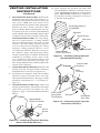
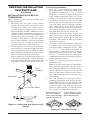
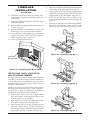
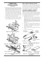
Model BK Installation
Follow all instructions provided in the blower
accessory kit.
1. Attach the power cord to the blower motor
by rmly pushing the two female terminals at
the end of the power cord onto the two spade
terminals on the blower motor (see Figure 25).
2. Attach green ground wire from power cord
to blower housing using screw provided (see
Figure 25). Tighten screws securely.
Figure 25 - Blower Model BK
Magnetic
Strips
Exhaust
Port
Screw
Green
Ground
Wire
Spade
Terminals
Side View
Lower Firebox
Cavity
Blower
Location

www.desatech.com
116647-01D18
3. Place the blower against the lower rear wall of
the rebox outer wrapper with the exhaust port
directed upward. The blower will t inside the
back opening and be held in position against
the back wall by the magnets (see Figure 25,
page 17).
4. Be certain that all wire terminals are securely
attached to terminals on blower motor and
that the screw retaining the green ground
wire is tight.
5. Mount speed control box to switch bracket
by placing the plastic control shaft forward
through the opening in the switch bracket (see
Figure 26).
6. While supporting speed control, secure control
shaft with lock nut by pushing and turning
lock nut with pliers clockwise until it is tight
against front panel. Place control knob pro-
vided on shaft.
7. Turn on power to duplex outlet if previ-
ously turned off per the warning in column
2, page 17.
8. Plug in blower power cord.
a. If your rebox is installed as a freestanding
unit with an accessory mantel, determine
whether the power cord will exit the left
side or the right side of the rebox. Route
power cord through exit hole and plug the
power cord into a wall receptacle near the
rebox.
b. If your rebox installation is recessed
and/or pre-wired, plug the power cord into
the duplex outlet provided. Refer to your
rebox owner’s manual for instructions
on wiring the duplex outlet.
CAUTION: Never touch the
blower wheel while in operation.
9. Check to make sure that the power cord is com-
pletely clear of the blower wheel and that there
are no other foreign objects in blower wheel.
Turn blower on and check for operation. Turn
blower off by turning knob fully counterclock-
wise before continuing.
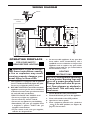
10. Peel off the backing paper and stick the sup-
plied wiring diagram decal on the rebox bot-
tom approximately 12" in front of the blower
(see Figure 27).
FIREPLACE
INSTALLATION
Continued
V
a
r
ia
b
le
F
a
n
S
w
it
c
h
W
h
it
e
W
h
ite
B
la
c
k
G
r
e
e
n
O
n
1
10
/
1
1
5
V
.
A
.C
.
Blower
Moto
r
B
la
c
k
B
l
a
c
k
B
l
a
c
k
O
f
f
Figure 26 - Attaching Speed Control to
Firebox
Figure 27 - Location of Wiring Diagram
Decal (Model May Vary From Illustration)
Wiring Diagram
Decal 12" in Front
of Blower
Speed
Control
Control
Shaft
Locknut
Control
Knob
Switch
Bracket
Blower
Plug-In
Duplex Outlet
(Located
underneath
rebox oor
against lower
right outside
wall)
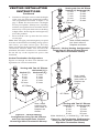
Model BKT Installation
Note: When installing the BKT thermostati-
cally-controlled blower, you must rst secure the
thermal switch bracket to the blower if it has not
already been factory installed.
1. Place the green ground wire with ring terminal
between the bottom hole on the thermal switch
bracket and the top ear hole on the blower
assembly. Insert the phillips screw into all
three pieces and tighten securely (see Figure
28, page 19).
2. Connect wire harness and power cord ter-
minals. Connect the blue jumper wire to the
blower motor terminal and the right side ter-
minal of the thermal switch. Connect the black
wire to the left side of the thermal switch and
the white wire to the other remaining blower
motor terminal.
Note: The power cord outer insulation sleeve may
have to be stripped slightly to allow enough wire
length to reach and make all connections. DO NOT
trim excessive length away. Just enable enough to
make all connections securely.

www.desatech.com
116647-01D 19
3. Place the blower against the lower rear wall of
the rebox outer wrapper with the exhaust port
directed upward and the thermodisc positioned
up near the replace bottom. The thermodisc
must be oriented near the replace bottom as
shown in Figure 28, in order to sense tempera-
ture and properly operate. The blower will be
held in position against the back wall by the
magnets incorporated onto the blower housing
(see Figure 28).
4. Be certain that all wire terminals are securely at-
tached to terminals on blower motor and thermal
switch and that the screw for the thermodisc
bracket and green ground wire is tight.
5. Mount the speed control box against the
mounting plate provided in the lower replace
cavity by placing the plastic control shaft
forward through the round hole (see Figure
26, page 18).
6. While supporting speed control, secure control
shaft with lock nut by pushing and turning
lock nut with pliers clockwise until it is tight
against mounting plate. Place control knob
provided on shaft (see Figure 26, page 18).
7. Check to make sure that the power cord is com-
pletely clear of the blower wheel and that there
are no other foreign objects in blower wheel.
Also double check all wire leads and make sure
wire routing is not pinched or in a precarious
position. Correct accordingly.
8. Turn on power to duplex outlet if previ-
ously turned off per the warning in column
2, page 17.
9. Plug in blower power cord to duplex outlet.
10. The blower will only run when the speed control
knob is in the ON position and the thermal switch
senses temperature after the replace begins to
heat up. The blower speed can be adjusted by
rotating the control knob. To turn off, turn knob
fully counterclockwise until it clicks off. If the
blower is ON and has been running with the
replace operating, the blower will continue to
run for a short time after the replace has been
turned off. As the thermal switch cools down,
the blower shuts down automatically.
11. Peel off the backing paper and stick the sup-
plied wiring diagram decal on the rebox bot-
tom approximately 12" in front of the blower
(see Figure 27, page 18).
FIREPLACE
INSTALLATION
Continued
Thermodisc
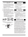
Figure 28 - Blower Model BKT
Air Flow
Direction
Route BKT Blower
Through This Area
Magnets
Blower
Location
Side View Firebox Bottom
Black
Wire
Phillips
Screw
Blue Wire
Ring
Terminal
on Green
Wire
White Wire
Thermal
Switch
Thermal
Switch
Bracket
Power
Cord
Air Flow
Direction
Magnetic
Strips
Figure 29 - Blower Wiring Diagram for
Thermostat-Controlled Models
Blower Wiring Diagram
CAUTION: Label all wires
prior to disconnection when
servicing controls. Wiring errors
can cause improper and dan-
gerous operation. Verify proper
operation after servicing.
Blue
Variable
Fan Switch
Fan Switch
(N.O.)
Green
White
On
110/115
V.A.C.
Blower
Motor
Black
Off
1
2
Black

www.desatech.com
116647-01D20
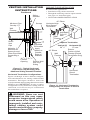
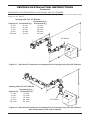
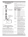
INSTALLING GAS pIpING TO
FIREpLACE LOCATION
WARNING: A qualified
service person must connect
replace to gas supply. Follow
all local codes.
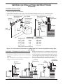
CAUTION: For propane/LP
units, never connect replace di-
rectly to the propane/LP supply.
This heater requires an external
regulator (not supplied). Install
the external regulator between
the replace and propane/LP
supply.
Installation Items Needed
Before installing replace, make sure you have the
items listed below.
• external regulator (supplied by installer)
• piping (check local codes)
• sealant (resistant to propane/LP gas)
• equipment shutoff valve *
• test gauge connection *
• sediment trap
• tee joint
• pipe wrench
• approved exible gas line with gas connector
(if allowed by local codes)
* A CSA design-certified equipment shutoff
valve with 1/8" NPT tap is an acceptable alterna-
tive to test gauge connection. Purchase the CSA
design-certied equipment shutoff valve from
your retailer.
For propane/LP connection only, the installer must
supply an external regulator. The external regula-
tor will reduce incoming gas pressure. You must
reduce incoming gas pressure to between 11 and 14
inches of water. If you do not reduce incoming gas
pressure, replace regulator damage could occur.
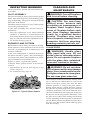
Install external regulator with the vent pointing
down as shown in Figure 30. Pointing the vent
down protects it from freezing rain or sleet.
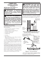
Figure 30 - External Regulator with Vent
Pointing Down (Propane/LP Only)
Propane/LP
Supply Tank
External
Regulator
Vent
Pointing
Down
CAUTION: Use only new,
black iron or steel pipe. Inter-
nally-tinned copper tubing may
be used in certain areas. Check
your local codes. Use pipe of
1/2" inside diameter or greater to
allow proper gas volume to re-
place. If pipe is too small, undue
loss of volume will occur.
Installation must include an equipment shutoff
valve, union and plugged 1/8" NPT tap. Locate NPT
tap within reach for test gauge hook up. NPT tap
must be upstream from replace (see Figure 31).
Figure 31 - Gas Connection
CSA Design-Certied
Equipment Shutoff Valve with
1/8" NPT Tap*
3" Minimum
Approved
Flexible Gas
Line
Cap Pipe Nipple Tee Joint
Sediment Trap/Drip Leg
Natural - From
Gas Meter (5.5"
W.C. to 10.5"
W.C. Pressure)
Propane/LP
From External
Regulator (11"
W.C. to 14"
W.C. Pressure)
* The CSA design-certied equipment shutoff
valve may be supplied with the appliance or you
can purchase it from your retailer.
FIREPLACE
INSTALLATION
Continued
Page is loading ...
Page is loading ...
Page is loading ...
Page is loading ...
Page is loading ...
Page is loading ...
Page is loading ...
Page is loading ...
Page is loading ...
Page is loading ...
Page is loading ...
Page is loading ...
Page is loading ...
Page is loading ...
Page is loading ...
Page is loading ...
Page is loading ...
Page is loading ...
Page is loading ...
Page is loading ...
-
 1
1
-
 2
2
-
 3
3
-
 4
4
-
 5
5
-
 6
6
-
 7
7
-
 8
8
-
 9
9
-
 10
10
-
 11
11
-
 12
12
-
 13
13
-
 14
14
-
 15
15
-
 16
16
-
 17
17
-
 18
18
-
 19
19
-
 20
20
-
 21
21
-
 22
22
-
 23
23
-
 24
24
-
 25
25
-
 26
26
-
 27
27
-
 28
28
-
 29
29
-
 30
30
-
 31
31
-
 32
32
-
 33
33
-
 34
34
-
 35
35
-
 36
36
-
 37
37
-
 38
38
-
 39
39
-
 40
40


Ask a question and I''ll find the answer in the document
Finding information in a document is now easier with AI
Related papers
-
Desa V36NH-A Owner's manual
-
Desa (V)T32EN-A Series, (V)T32EP-A Series User manual
-
 Vexar CD36T-M Owner's manual
-
Desa (V)T32P SERIES User manual
-
-
FMI K42EP Owner's manual
-
FMI (V)K36EP SERIES User manual
-
-
FMI VK36NH User manual
-

Other documents
-
Gibraltar Building Products RW26B Operating instructions
-
-
-
-
-
Gibraltar Building Products RW26G Operating instructions
-
-
-
-
FMI T32ENRB-A User manual