Page is loading ...

USA
SERVICE OFFICE
Dometic Corporation
1120 North Main Street
Elkhart, IN 46514
CANADA
Dometic Corporation
46 Zatonski, Unit 3
Brantford, ON N3T 5L8
CANADA
SERVICE CENTER &
DEALER LOCATIONS
Please Visit:
www.eDometic.com
RECORD THIS INFORMATION FOR FUTURE
REFERENCE:
FRTA Model Number
FRTA Serial Number
Hardware Model Number
Hardware Serial Number
Date Purchased
Retailer / Qualied Installer
Read these instructions carefully. These
instructions MUST stay with this product.
REVISION B
Form No. 3315087.000 06/17
(French 3315088.000_B)
©2017 Dometic Corporation
LaGrange, IN 46761
SUNCHASER
8500
9000
GEARED AWNING
FABRIC ROLLER TUBE ASSEMBLY (FRTA)
UNIVERSAL SERIES HARDWARE
G8273000
INSTALLATION
INSTRUCTIONS

2
TABLE OF CONTENTS
INTRODUCTION ....................................................................................................................................................................2
DOCUMENT SYMBOLS ........................................................................................................................................................2
IMPORTANT SAFETY INSTRUCTIONS ................................................................................................................................ 3
A. Recognize Safety Information ...................................................................................................................................3
B. Understand Signal Words ..........................................................................................................................................3
C. Supplemental Directives ............................................................................................................................................ 3
D. General Safety Messages .........................................................................................................................................3
GENERAL INFORMATION .....................................................................................................................................................3
A. Optional Components ................................................................................................................................................ 3
SPECIFICATIONS .................................................................................................................................................................. 4
A. Hardware Dimensions ...............................................................................................................................................4
PREPARE FOR INSTALLATION ............................................................................................................................................5
A. Installing The Door Roller And Edge Guard (Optional) ..............................................................................................5
B. Preparing The Awning Rail ........................................................................................................................................5
C. Preparing The Awning For Installation ....................................................................................................................... 5
D. Determining The Awning Location ............................................................................................................................. 6
INSTALL THE AWNING ..........................................................................................................................................................7
A. Installing The LED Light Switch (If Applicable) ..........................................................................................................7
B. Inserting The Awning Fabric Into The Awning Rail ....................................................................................................7
C. Installing The Top Mounting Brackets ........................................................................................................................8
D. Installing The Bottom Mounting Brackets ..................................................................................................................9
E. Installing Stop Bolts .................................................................................................................................................10
F. Securing The Awning Fabric To The Awning Rail ....................................................................................................10
G. Installing The Gear Cover Assembly (RH Side) ...................................................................................................... 11
H. Installing Cover on LH Side .....................................................................................................................................12
I. Connecting The LED Lights (If Applicable) .............................................................................................................. 12
VERIFY THE INSTALLATION ..............................................................................................................................................13
A. Testing Operation ....................................................................................................................................................13
B. Securing The Awning For Travel .............................................................................................................................13
C. Keeping The Literature ............................................................................................................................................13
INTRODUCTION
This awning (hereinafter referred to as “awning,” or “product”) is designed and intended for use on RVs with straight sides.
This awning consists of two major assemblies. The Fabric Roller Tube Assembly (hereinafter referred to as “FRTA”), and
the Awning Hardware (including arm assemblies, rafters, and mounting brackets).
This awning can be installed by one person with brief help from additional personnel. Use these instructions to ensure cor-
rect installation, function, and operation of product.
Dometic Corporation reserves the right to modify appearances and specications without notice.
DOCUMENT SYMBOLS
Indicates additional information that is NOT related
to physical injury.
Indicates step-by-step instructions.

3
IMPORTANT SAFETY INSTRUCTIONS
This manual has safety information and instructions to help
you eliminate or reduce the risk of accidents and injuries.
A. Recognize Safety Information
This is the safety alert symbol. It is used to
alert you to potential physical injury hazards.
Obey all safety messages that follow this
symbol to avoid possible injury or death.
B. Understand Signal Words
A signal word will identify safety messages and
property damage messages, and will indicate the
degree or level of hazard seriousness.
indicates a hazardous situation that,
if NOT avoided, could result in death or serious in-
jury.
indicates a hazardous situation that,
if NOT avoided, could result in minor or moderate
injury.
is used to address practices NOT
related to physical injury.
C. Supplemental Directives
Read and follow all safety information and
instructions to avoid possible injury or death.
Read and understand these instructions be-
fore [installing / using / servicing / performing
maintenance on] this product.
Incorrect [installation / operation / servicing /
maintaining] of this product can lead to seri-
ous injury. Follow all instructions.
The installation MUST comply with all ap-
plicable local and national codes, including
the latest edition of the following standards:
U.S.A.
● ANSI/NFPA70, National Electrical Code
(NEC)
● ANSI/NFPA 1192, Recreational Vehicles
Code
CANADA
● CSA C22.1, Parts l & ll, Canadian Electri-
cal Code
● CSA Z240 RV Series, Recreational
Vehicles
D. General Safety Messages
Failure to obey the following warn-
ings could result in death or serious injury:
● This product MUST be [installed / serviced] by a
qualied service technician.
● Do NOT modify this product in any way. Modica-
tion can be extremely hazardous.
● IMPACT OR CRUSH HAZARD. This product
should be installed in a controlled environment
(inside). Do NOT install product during windy
conditions, or when wind is expected. Otherwise,
product could move unpredictably, become un-
stable, and could [detach / bend / collapse].
GENERAL INFORMATION
A. Optional Components
(1) 830304 Door Roller Kit
(1) 830304.003 Door Roller Kits (50 Pack)
(2) 3314573.001 Top Bracket Spacer Kit (1 Set)
(1) 3109623.550 Top Bracket Spacers (50 Pack)
(1) 3104781.004 Bottom Spacer Kit (1 Pair)
(1) 3104781.103 Bottom Spacer Kits (10 Pair)

4
A. Hardware Dimensions
MODEL
SERIES
G8273000
.401#
G8273000
.402#
G8273000
.405#
G8273000
.407#
*G8273000
.408#
.501# .502# .505# .507# .508#
Height Range
76″ - 86″
(193 cm - 218 cm)
64″ - 76″
(163 cm - 193 cm)
78″ - 91″
(198 cm - 231 cm)
94″ - 107″
(239 cm - 272 cm)
Short 64″ - 76″
(163 cm - 193 cm)
Tall 76″ - 86″
(193 cm - 218 cm)
Main Arm
Length
73″
(185 cm)
61″
(155 cm)
76″
(193 cm)
92″
(234 cm)
Short 61″
(155 cm)
Tall 73″
(185 cm)
Adjustable
Arm Length
57″
(145 cm)
57″
(145 cm)
72″
(183 cm)
72″
(183 cm)
Short 57″
(145 cm)
Tall 57″
(145 cm)
Main Rafter
Length
66″
(168 cm)
54″
(137 cm)
71″
(180 cm)
71″
(180 cm)
Short 54″
(137 cm)
Tall 66″
(168 cm)
Secondary
Rafter Length
32 1/2″
(82.5 cm)
44 1/2″
(113 cm)
53 1/2″
(136 cm)
53 1/2″
(136 cm)
Short 44 1/2″
(113 cm)
Tall 32 1/2″
(82.5 cm)
Duty
.40(X)# Standard
.50(X)# Heavy
Standard Duty hardware may be used if the awning FRTA is 21′ (6 m) wide (or less).
Heavy Duty hardware MUST be used if the awning FRTA is greater than 21′ (6 m) wide.
*Model G8273000.(X)08# hardware has (1) Short and (1) Tall Arm/Rafter assembly. This hardware is intended for use
on fth wheel RVs.
SPECIFICATIONS

5
B. Preparing The Awning Rail
Make sure awning rail is parallel to
RV oor, and is NOT warped or curved before in-
stalling awning fabric. If awning rail is NOT straight,
awning fabric may wrinkle or stretch.
Select the desired awning rail end (on the RV) into
which the awning fabric will be inserted. Flare (wid-
en) that end of the rail with a athead screwdriver,
and remove (le) sharp edges. See FIG. 3.
If the awning is equipped with LED lights, are
the top (of the awning rail opening) ONLY.
FIG. 3
Before
After
LED Awnings:
Flare Top Only
Typical Awnings:
Flare Top And Bottom
C. Preparing The Awning For Installation
The awning requires minor preparation before in-
stalling on an RV.
1. Carefully lay the FRTA on a clean, well padded
“V” trough (or other well protected surface) to
prevent fabric damage.
2. Insert the right hand top casting into the corre-
sponding main arm. See FIG. 4.
FIG. 4
RH Top Casting
1/4″-20 X 1/2″
Hex Head Screw
Main Arm
PREPARE FOR INSTALLATION
A. Installing The Door Roller And Edge
Guard (Optional)
Do NOT allow corner of entry door
to contact awning fabric. Otherwise, premature
wear or tearing of awning fabric could occur.
If there’s potential for a squared corner entry door
to contact awning fabric, a door roller kit (NOT IN-
CLUDED) must be installed.
Rounded corner doors may NOT require a
door roller kit if there is no potential for dam-
age to awning fabric.
See subsection, "A. Optional Components"
on page (3) to order door roller kits.
1. Install the door roller. See FIG. 1.
a. Place the door roller at the upper cor-
ner (opposite to hinge) of the outer entry
door. Face the roller out, and 1/4″ to 3/8″
(6.35 mm to 3.75 mm) above the door.
b. Place and tighten the self-drilling screws
(provided) through the mounting holes and
into the door.
FIG. 1
Position Wheel
Directly Over
Edge Of Door
Outer Entry
Door
1/4″ - 3/8″
(6.35 mm -
3.75 mm)
(Above Door)
2. Clip the door edge guard onto the upper corner
(opposite to hinge) of the inner screen door. See
FIG. 2.
FIG. 2
Door Edge
Guard
Inner Screen
Door

6
Install the top bracket spacers if the
awning rail is too wide (has drip chan-
nel) and interferes with the top mount-
ing brackets. See FIG. 9.
See subsection "A. Optional Compo-
nents" on page (3) to order top
bracket spacers.
FIG. 6
Top Mounting Bracket
Mounting Over Rail
Awning Rail
FRTA
FIG. 7
Mounting Below Rail
Top Mounting Bracket
Awning Rail
FRTA
FIG. 8
Mounting On Rail
Top Mounting Bracket
Awning Rail
FRTA
3. Place the 1/4″-20 X 1/2″ hex head screw (with
lock washer) through the main arm and into the
top casting. Tighten to 65-80 in·lb torque. See
FIG. 4.
4. Install Top Casting Shelf as shown. See FIG. 5.
FIG. 5
RH Top Casting
Top Casting
Shelf
5. Repeat steps (2) through (4) for the opposite
side.
D. Determining The Awning Location
1. IMPACT OR CRUSH HAZARD.
Verify mounting surface on RV is at, has solid
structural backing where fasteners penetrate
surface, and will safely and securely support
product. Otherwise, product may become un-
stable and could [detach / bend / collapse]. Fail-
ure to obey this warning could result in death or
serious injury.
Find a solid structure in the RV wall for support
of the top mounting brackets.
Do NOT fasten top mounting
bracket over awning rail and against rubber cap
molding (if RV’s roof construction has rounded
corners). Otherwise, water leakage could occur.
The relationship between the solid structure and
the awning rail will determine the location of the
top mounting brackets. Possible positions for
the top mounting brackets include:
● Mounting OVER the awning rail. See FIG. 6.
Do NOT use this position if the top
mounting brackets will contact rub-
ber cap molding on the RV (roof with
rounded corners).
● Mounting BELOW the awning rail. See FIG. 7.
● Mounting ON the awning rail. See FIG. 8.
PREPARE FOR INSTALLATION

7
FIG. 9
Top Mounting
Bracket
Awning Rail
With Drip
Channel
Top Bracket
Spacer
2. Ensure the arm assemblies do not restrict use of
doors, windows, etc. See FIG. 10.
PREPARE FOR INSTALLATION
INSTALL THE AWNING
A. Installing The LED Light Switch
(If Applicable)
An LED light switch (installer supplied) is required
for awning models equipped with an LED light strip.
Skip this subsection if the awning is NOT
equipped with an LED light strip.
1. Do NOT expose switch to weath-
er, extreme temperatures, or long hours in direct
sunlight.
Find a suitable location for the LED switch instal-
lation.
2. Route wiring (inside the RV) to the general loca-
tion where connections to the awning hardware
will be made.
Allow enough wiring length to pass
through the outside of the RV wall (hole
will be drilled later) for connection to the
awning.
The wiring hole location will be near the
RH top casting. See FIG. 4.
3. Disconnect the positive (+) 12
Vdc terminal from supply battery. Otherwise,
damage to unit could occur.
Make the appropriate wiring connections inside
the RV.
Wiring connections to the awning (through
the outside RV wall) will be made later.
The LED kit has a (6 A) rating. Wiring
MUST be connected to an appropriately
rated, fused circuit.
B. Inserting The Awning Fabric Into The
Awning Rail
1. Unfurl the awning fabric one revolution before
inserting the fabric (with awning roller cover, if
equipped) into the awning rail.
Unfurling one revolution will allow enough
space between the RV wall and awning
hardware to guide the fabric into the rail.
2. LIFTING HAZARD. Use proper
lifting technique and control when lifting product.
Failure to obey this caution could result in injury.
With one person grasping each arm assembly,
carefully lift the entire awning assembly upright.
Then carry the awning to the prepared (ared)
awning rail end. See FIG. 11.
FIG. 11
Awning
Rail
Arm
Assembly
FRTA
FIG. 10
Arm Assemblies

8
2. Push in one side tab of arm safety lock, then the
other to disengage the main rafter from the main
arm. See (FIG. 13).
FIG. 13
Back View
Arm Safety
Lock
Main Rafter
Main Arm
3. Make sure the main rafter is aligned directly be-
hind and centered with the main arm. Then care-
fully pull the main rafter away from the main arm
(toward the RV), and mark the hole locations for
the top mounting bracket. See FIG. 6, FIG. 7,
FIG. 8, & FIG. 14.
FIG. 14
Top Mounting
Bracket
Main
Arm
#14-10 X 3″ Hex
Head Screw
Main
Rafter
4. FIRE OR ELECTRICAL SHOCK
HAZARD. Verify there are no obstacles inside
RV’s roof and/or walls (wires, pipes, etc.). Shut
OFF gas supply, disconnect 120 Vac power from
RV, and disconnect positive (+) 12 Vdc terminal
from supply battery BEFORE drilling or cutting
into RV. Failure to obey these warnings could
result in death or serious injury.
Drill 3/16″ diameter holes through the marked
mounting hole locations and into the solid struc-
ture of the RV.
Drill 7/32″ diameter holes if drilling into
steel.
3. While one person guides the awning fabric into
the awning rail, carefully move (carry) the aw-
ning assembly to the predetermined location.
See FIG. 11.
To determine correct awning location, see
subsection, "D. Determining The Awning
Location" on page (6).
A stepladder may be necessary to reach
the awning rail.
At least two other people are required to
hold and control awning hardware until:
● both top mounting brackets are cor-
rectly installed;
● both bottom mounting brackets are
correctly installed;
● both patio feet are securely latched
into bottom mounting brackets.
C. Installing The Top Mounting Brackets
1. When the awning is in the predetermined loca-
tion, extend both the adjustable arms down to
help support the awning assembly.
To determine the correct awning location,
see subsection, "D. Determining The Aw-
ning Location" on page (6).
a. Pull the lift handle out and CAREFULLY ex-
tend the adjustable arm until the patio foot
contacts the oor / ground. See FIG. 12.
b. With the FRTA at the same height (ap-
proximately) as the awning rail, release the
lift handle to lock in position. See FIG. 7 &
FIG. 12.
c. Repeat steps (a) and (b) for the opposite side.
FIG. 12
Main Arm
Lift Handle
Adjustable
Arm
Patio Foot
INSTALL THE AWNING

9
5. ALWAYS use sealant on (clean)
parts and surfaces where fasteners enter RV’s
roof and/or walls. Otherwise, water leakage
could occur.
Apply sealant to the #14-10 X 3″ hex head screw
threads. Then place and tighten screws through
the top mounting bracket and into the solid
structure of the RV. See FIG. 6, FIG. 7, FIG. 8,
& FIG. 14.
6. Repeat steps (2) through (5) for the opposite
side.
7. Lift and place the top casting shelf onto the
top mounting bracket’s top pivot. Then push
(squeeze) the main rafter into the main arm until
the arm safety lock snaps securely in place. See
FIG. 13 & FIG. 15.
FIG. 15
Top Mounting
Bracket
Main
Arm
Main Rafter
Top Pivot
Top Casting Shelf
(Directly Behind Gear Box)
Gear
Box
8. Repeat step (7) for the opposite side.
D. Installing The Bottom Mounting
Brackets
1. Make sure the top casting shelf is still resting
on the top mounting bracket’s top pivot. See
FIG. 15.
2. IMPACT OR CRUSH HAZARD.
Verify mounting surface on RV is at, has solid
structural backing where fasteners penetrate
surface, and will safely and securely support
product. Otherwise, product may become un-
stable and could [detach / bend / collapse]. Fail-
ure to obey this warning could result in death or
serious injury.
Find a solid structure in the RV wall to install the
bottom mounting bracket. Then adjust the arm
to place the bottom mounting bracket in the de-
sired mounting position. See FIG. 12, FIG. 15,
& FIG. 16.
Mount directly into the RV oor line, over
molding, etc. If installing over RV molding,
a bottom spacer MUST be used.
See subsection "A. Optional Compo-
nents" on page (3) to order bottom
spacer kits.
a. While one person holds and controls the
main arm, pull the lift handle out.
b. Slide the adjustable arm up or down until the
bottom mounting bracket is in the desired
mounting position.
c. Release the lift handle to lock in position.
The lift handle MUST be locked in
position to complete installation (later
steps).
FIG. 16
Bottom Mounting Bracket
Bottom Spacer
RV Molding
Adjustable
Arm
Main Arm
3. Square the arm assembly to the RV and FRTA.
See FIG. 17.
Measuring from a door or window frame is
acceptable.
FIG. 17
Floor Line
Square
To RV
And
FRTA
FRTA
Arm Assembly
4. While holding the bottom mounting bracket
against the RV wall, mark the hole locations.
See FIG. 16.
INSTALL THE AWNING

10
FIG. 18
Main Arm
Adjustable
Arm
5/16″-18
Lock Nut
Patio Foot
Bottom Mounting
Bracket
5/16″-18 X 1″
Shoulder
(Stop) Bolt
3. Pull the lift handle out and slide the main arm
down until it rests on the stop bolt. Then release
the lift handle to lock in position. See FIG. 12.
Top casting should now clear top pivot by
1/2″ when awning closes. See FIG. 15.
4. Repeat steps (1) through (3) for opposite side.
5. Remove and discard the shelf.
F. Securing The Awning Fabric To The
Awning Rail
1. PINCH HAZARD. Maintain a
horizontal distance of at least 16″ between fully
open awning and any permanent object. Failure
to obey this caution could result in injury.
2. IMPACT OR STABBING HAZ-
ARD. Do NOT overreach. Stay alert, and main-
tain control of crank. Keep people clear of area
while [opening / closing] product. Keep proper
footing and balance at all times. Failure to obey
these warnings could result in death or serious
injury.
ENTANGLEMENT HAZARD.
Rotating parts. Keep hands, hair, and clothing
away from moving parts. Failure to obey this
caution could result in injury.
Do NOT rotate crank faster than
2 revolutions per second (120 RPM). Do NOT
use an impact driver, or exceed 90 in·lb maxi-
mum torque. Otherwise, product damage could
occur.
Open and close the awning four or ve times to
allow for natural self adjustment of awning fab-
ric. See Operating Instructions.
5. FIRE OR ELECTRICAL SHOCK
HAZARD. Verify there are no obstacles inside
RV’s roof and/or walls (wires, pipes, etc.). Shut
OFF gas supply, disconnect 120 Vac power from
RV, and disconnect positive (+) 12 Vdc terminal
from supply battery BEFORE drilling or cutting
into RV. Failure to obey these warnings could
result in death or serious injury.
Drill 3/16″ diameter holes through the marked
mounting hole locations and into the solid struc-
ture of the RV.
Drill 7/32″ diameter holes if drilling into
steel.
6. ALWAYS use sealant on (clean)
parts and surfaces where fasteners enter RV’s
roof and/or walls. Otherwise, water leakage
could occur.
Apply sealant to the #14 hex head screw
threads. Then place and tighten the screws
through the bottom mounting bracket and into
the solid structure of the RV.
7. Repeat steps (1) through (6) for the opposite
side.
E. Installing Stop Bolts
Install shoulder bolt (stop bolt) to
help prevent over-travel of arm assembly.
Before proceeding with stop bolt installation:
● Bottom mounting bracket MUST be
installed.
● Patio foot MUST be latched into bottom
mounting bracket.
● Lift handle MUST be locked in position.
1. Pull the lift handle out and slide the main arm up
by one hole only. Then release the lift handle to
lock in position. See FIG. 12.
2. Place a 5/16″-18 X 1″ shoulder (stop) bolt through
the highest, fully exposed hole in the adjustable
arm (nearest bottom edge of main arm). Then
secure with a 5/16″-18 lock nut. See FIG. 18.
INSTALL THE AWNING

11
3. Verify alignment of the awning fabric, and proper
nesting of hardware.
a. If there is misalignment, adjust the arm as-
sembly by loosening the back channel and
top mounting bracket screws and move the
back channel accordingly. (Retighten the
screws.)
b. Cycle the awning again to check alignment.
4. Ensure arm assemblies are still nested correctly,
then mark the location of the awning fabric edg-
es on the awning rail.
5. Pull one edge of the awning fabric approximate-
ly 1/4″ (6 mm) beyond marked position. Then
secure with a #6 X 7/16″ TEK screw through the
awning rail (approximately 2″ (50 mm) from fab-
ric edge). See FIG. 19.
FIG. 19
2″
(50 mm)
Awning Rail
Fabric Edge
#6 X 7/16″
TEK Screw
6. Pull to stretch the opposite edge of the awning
fabric approximately 3/4″. Then secure with a #6
X 7/16″ TEK screw through the awning rail (ap-
proximately 2″ (50 mm) from fabric edge).
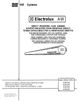
G. Installing The Gear Cover Assembly
(RH Side)
1. Open the awning far enough for the cover to t
behind the top casting. See “Opening The Aw-
ning” in Operating Instructions.
2. Place the back cover against the top casting and
gear box. See FIG. 20.
INSTALL THE AWNING
FIG. 20
Back
Cover
Top Casting
Front
Cover
Gear Box
3. Place the front cover against the back cover to
enclose the top casting and gear box. Then push
until the tabs snap securely in place. See FIG. 20.
FIG. 21
Back View
Gear Cover
Assembly
Optional Screw
Locations
Top Casting
4. OPTIONAL: Place and tighten cover screws
through the back cover and into the front cover.
See FIG. 20 & FIG. 21.
If tabs break or will NOT securely snap in
place, this step is mandatory.
Use #8 x 1/2" long pan head tapping
screws for plastic.

12
I. Connecting The LED Lights
(If Applicable)
Skip this subsection if the awning is NOT
equipped with an LED light strip.
1. FIRE OR ELECTRICAL SHOCK
HAZARD. Verify there are no obstacles inside
RV’s roof and/or walls (wires, pipes, etc.). Shut
OFF gas supply, disconnect 120 Vac power from
RV, and disconnect positive (+) 12 Vdc terminal
from supply battery BEFORE drilling or cutting
into RV. Failure to obey these warnings could
result in death or serious injury.
With awning open, drill (1) 5/8″ diameter hole
through the outside wall of RV (near the RH top
casting and under the awning rail).
Ensure the location will allow LED wiring to
pass through the wall without interference.
2. Do NOT pinch wiring or allow wir-
ing to rub against sharp edges. If wiring is dam-
aged, it MUST be replaced by a qualied service
technician.
Use a grommet (installer supplied) when routing
wiring through the RV wall.
If a grommet is NOT used, use heat-shrink
tubing where wiring will pass through the
RV wall.
3. ALWAYS seal wiring against
weather and moisture where wiring enters RV’s
roof and/or walls. Otherwise, water leakage
could occur.
Pull the wiring through the wiring hole (and
grommet).
If a grommet is NOT used, make sure
sealant will also provide effective and per-
manent protection against wire damage.
4. Make sure the positive (+) 12
Vdc terminal is disconnected from supply bat-
tery. Otherwise, damage to unit could occur.
Connect LED switch wiring to the factory pre-
wired LED light strip.
See instructions included with your LED
switch kit (installer supplied) for additional
wiring instructions.
5. Secure the wiring to prevent pinching or other
damage during awning operation.
Allow enough slack in the wiring to safely
accommodate possible fabric movement.
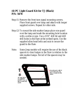
H. Installing Cover on LH Side
FIG. 22
FIG. 23
1. While the awning is open from the previous step,
place the LH back cover against the top casting
while aligning the casting pin into the cover hole
(see FIG. 22).
2. Place the LH front cover against the back cover,
aligning pin and push covers together until the
tabs snap securely in place.
3. OPTIONAL: Place and tighten cover screws
through the back cover and into the front cover
(see FIG. 23).
INSTALL THE AWNING
Back Cover
Top Casting
Front Cover
Optional Screw Locations

13
VERIFY THE INSTALLATION
A. Testing Operation
Operate the awning according to the Operating
Instructions to verify all parts are functioning cor-
rectly.
B. Securing The Awning For Travel
1. Fully close the awning. See “Closing The Aw-
ning” in Operating Instructions.
2. Verify the awning is secure for travel. See “Pre-
paring The Awning For Travel” in Operating In-
structions.
C. Keeping The Literature
Instructions contain valuable information for prod-
uct use and consumer safety.
Keep BOTH the Installation and Operat-
ing Instructions with product.
/