Page is loading ...

ILD 2300-2
ILD 2300-5
ILD 2300-10
ILD 2300-20
ILD 2300-50
ILD 2300-100
ILD 2300-200
ILD 2300-300
ILD2300-2LL
ILD2300-10LL
ILD2300-20LL
ILD2300-50LL
ILD2300-2BL
ILD2300-5BL
ILD2310-50BL
ILD2300-2DR
ILD 2310-10
ILD 2310-20
ILD 2310-40
ILD 2310-50
Instruction Manual
optoNCDT 2300

MICRO-EPSILON
MESSTECHNIK
GmbH & Co. KG
Königbacher Strasse 15
94496 Ortenburg / Germany
Tel. +49 (0) 8542 / 168-0
Fax +49 (0) 8542 / 168-90
e-mail [email protected]
www.micro-epsilon.com
EtherCAT® is registered trademark and patented technology,
licensed by Beckhoff Automation GmbH, Germany.

optoNCDT 2300
Contents
1. Safety ...................................................................................................................................... 11
1.1 Symbols Used ............................................................................................................................................... 11
1.2 Warnings ........................................................................................................................................................ 11
1.3 Notes on CE Marking .................................................................................................................................... 12
1.4 Intended Use ................................................................................................................................................. 13
1.5 Proper Environment ....................................................................................................................................... 13
2. Laser Class ............................................................................................................................. 14
3. Functional Principle, Technical Data ..................................................................................... 17
3.1 Short Description ........................................................................................................................................... 17
3.2 Real Time Control (A-RTSC) .......................................................................................................................... 18
3.3 Exposure Control ........................................................................................................................................... 18
3.4 Technical Data ............................................................................................................................................... 19
3.5 Indicator Elements at Sensor ........................................................................................................................ 25
4. Delivery ................................................................................................................................... 26
4.1 Unpacking ...................................................................................................................................................... 26
4.2 Storage .......................................................................................................................................................... 26
5. Installation .............................................................................................................................. 27
5.1 Diffuse Reflection ........................................................................................................................................... 29
5.2 Direct Reflection ............................................................................................................................................. 32
5.3 Electrical Connections ................................................................................................................................... 35
5.3.1 Connection Possibilities ............................................................................................................... 35
5.3.2 Supply Voltage ............................................................................................................................. 37
5.3.3 Laser on ........................................................................................................................................ 37
5.3.4 Input and Outputs......................................................................................................................... 38
5.3.5 Ethernet ........................................................................................................................................ 39
5.3.6 EtherCAT....................................................................................................................................... 40
5.3.7 Connector and Sensor Cable....................................................................................................... 41

optoNCDT 2300
6. Operation ................................................................................................................................ 42
6.1 Getting Ready for Operation ......................................................................................................................... 42
6.2 Operation via Ethernet ................................................................................................................................... 42
6.2.1 Preconditions ................................................................................................................................ 42
6.2.2 Access via Ethernet ...................................................................................................................... 44
6.2.3 Measurement Presentation via Web Browser .............................................................................. 45
6.2.4 Video Signal via Web Browser ..................................................................................................... 47
6.3 Programming via ASCII Commands ............................................................................................................. 48
6.4 Timing, Measurement Value Flux .................................................................................................................. 48
7. Control Menu, Set Sensor Parameter ................................................................................... 50
7.1 Preliminary Remarks to the Adjustments ...................................................................................................... 50
7.2 Overview Parameter ....................................................................................................................................... 50
7.3 Login, Change User Level ............................................................................................................................. 50
7.4 Default Settings .............................................................................................................................................. 52
7.4.1 Measurement Program ................................................................................................................. 52
7.4.2 Measuring Rate ............................................................................................................................ 52
7.4.3 Baud Rate for RS422 .................................................................................................................... 53
7.4.4 Averaging, Error Processing, Spike Correction and Statistics .................................................... 56
7.4.4.1 Measurement Averaging ............................................................................................. 57
7.4.4.2 Spike Correction ......................................................................................................... 59
7.4.4.3 Statistical values .......................................................................................................... 61
7.4.5 Setting Zero and Masters ............................................................................................................. 62
7.4.6 Material Data Base ....................................................................................................................... 63
7.5 Data Output.................................................................................................................................................... 64
7.5.1 Digital Interfaces ........................................................................................................................... 64
7.5.2 Output Data Rate .......................................................................................................................... 65
7.6 Measurement Control ................................................................................................................................... 65
7.6.1 Triggering ...................................................................................................................................... 65
7.6.1.1 Signal Processing without Trigger .............................................................................. 68
7.6.1.2 Signal Processing - Value Output Trigger .................................................................. 69
7.6.1.3 Signal Processing - Trigger for Acquiring Values ....................................................... 70
7.6.1.4 Signal Processing - Trigger for Outputting all Values ................................................. 71

optoNCDT 2300
7.6.2 Trigger Counter............................................................................................................................. 73
7.6.2.1 General ........................................................................................................................ 73
7.6.2.2 Trigger ID (T) ............................................................................................................... 73
7.6.2.3 Trigger Event Counter ................................................................................................. 73
7.6.2.4 Trigger Measurement Value Counter .......................................................................... 74
7.6.2.5 Example ....................................................................................................................... 74
7.6.2.6 Function ....................................................................................................................... 75
7.6.2.7 Presets for Trigger Mode and Trigger Edge ............................................................... 76
7.6.3 Synchronization ............................................................................................................................ 77
7.7 Loading, Saving, Extras ................................................................................................................................ 79
7.7.1 Loading/Saving Settings .............................................................................................................. 79
7.7.2 Extras ............................................................................................................................................ 80
8. Digital Interfaces .................................................................................................................... 81
8.1 Preliminary Remarks ...................................................................................................................................... 81
8.2 Ethernet .......................................................................................................................................................... 81
8.2.1 Default Settings ............................................................................................................................ 81
8.2.2 Data Format Output Values, Measurement Value Frame Ethernet .............................................. 82
8.2.3 Measurement Data Transmission to a Measurement Value Server, Measurement Value Block 86
8.2.4 Ethernet Video Signal Transmission ............................................................................................ 88
8.3 RS422............................................................................................................................................................. 88
8.4 EtherCAT ........................................................................................................................................................ 90
8.5 Change Ethernet to EtherCAT ....................................................................................................................... 90
9. Value Output ........................................................................................................................... 91
9.1 RS422............................................................................................................................................................. 91
9.1.1 Possible Output Values and Output Sequence (RS422) ............................................................. 93
9.1.2 Error Codes .................................................................................................................................. 94
9.2 Ethernet .......................................................................................................................................................... 95
9.3 EtherCAT ........................................................................................................................................................ 95
9.4 Analog Output ................................................................................................................................................ 96
9.5 Error Handling ............................................................................................................................................... 96

optoNCDT 2300
10. Instructions for Operating...................................................................................................... 97
10.1 Reflection Factor of the Target Surface ......................................................................................................... 97
10.2 Error Influences ............................................................................................................................................. 98
10.2.1 Light from other Sources ............................................................................................................. 98
10.2.2 Color Differences ......................................................................................................................... 98
10.2.3 Surface Roughness ..................................................................................................................... 98
10.2.4 Temperature Influences ............................................................................................................... 99
10.2.5 Mechanical Vibration ................................................................................................................... 99
10.2.6 Movement Blurs ........................................................................................................................... 99
10.2.7 Angle Influences ........................................................................................................................ 100
10.3 Optimizing the Measuring Accuracy .......................................................................................................... 101
10.4 Cleaning ....................................................................................................................................................... 102
10.5 Protective Housing ..................................................................................................................................... 102
10.5.1 Versions ...................................................................................................................................... 102
10.5.2 Guidelines .................................................................................................................................. 103
10.5.3 Delivery ...................................................................................................................................... 103
11. RS422 Connection with USB Converter .............................................................................. 106
12. Software Support with MEDAQLib ...................................................................................... 106
13. Liability for Material Defects ................................................................................................ 107
14. Decommissioning, Disposal ................................................................................................ 107
15. Service, Repair ..................................................................................................................... 108
Appendix
A 1 Optional Accessories ................................................................................................................................... 109
A 2 Factory Setting ............................................................................................................................................. 113
A 2.1 Parameters ................................................................................................................................................... 113
A 2.2 Set Default Settings ..................................................................................................................................... 114
A 3 PC2300-0.5/Y ............................................................................................................................................... 115
A 4 PC2300-x/OE ............................................................................................................................................... 116
A 5 IF2004/USB .................................................................................................................................................. 117

optoNCDT 2300
A 6 ASCII Communication with Sensor ............................................................................................................. 118
A 6.1 General ........................................................................................................................................................ 118
A 6.2 Commands Overview .................................................................................................................................. 120
A 6.3 General Commands .................................................................................................................................... 124
A 6.3.1 General ...................................................................................................................................... 124
A 6.3.1.1 Help ........................................................................................................................... 124
A 6.3.1.2 Sensor Information ................................................................................................... 124
A 6.3.1.3 Synchronization ........................................................................................................ 125
A 6.3.1.4 Booting the Sensor .................................................................................................. 125
A 6.3.1.5 Reset Counter ........................................................................................................... 126
A 6.3.1.6 Switching the Command Reply, ASCII Interface ..................................................... 126
A 6.3.1.7 PRINT ........................................................................................................................ 127
A 6.3.2 User Level ................................................................................................................................... 128
A 6.3.2.1 Change of the User Level .......................................................................................... 128
A 6.3.2.2 Change to User in the User Level ............................................................................. 128
A 6.3.2.3 User Level Request ................................................................................................... 128
A 6.3.2.4 Set Standard User ..................................................................................................... 128
A 6.3.2.5 Change Password ..................................................................................................... 128
A 6.3.3 Triggering .................................................................................................................................... 129
A 6.3.3.1 Trigger Selection ...................................................................................................... 129
A 6.3.3.2 Effect of the Trigger Input .......................................................................................... 129
A 6.3.3.3 Trigger Level ............................................................................................................. 129
A 6.3.3.4 Number of Measurement Values Displayed ............................................................. 130
A 6.3.3.5 Software Trigger Pulse .............................................................................................. 130
A 6.3.3.6 Trigger Output all Values ........................................................................................... 130
A 6.3.4 Interfaces .................................................................................................................................... 131
A 6.3.4.1 Ethernet ..................................................................................................................... 131
A 6.3.4.2 Setting Measurement Server .................................................................................... 131
A 6.3.4.3 Setting RS422 ........................................................................................................... 131
A 6.3.4.4 Change between Ethernet / EtherCAT ...................................................................... 132
A 6.3.4.5 Units Web-Interface ................................................................................................... 132
A 6.3.5 Load / Save Settings .................................................................................................................. 132
A 6.3.5.1 Save Parameter ........................................................................................................ 132
A 6.3.5.2 Load Parameter ........................................................................................................ 132
A 6.3.5.3 Default Settings ........................................................................................................ 132

optoNCDT 2300
A 6.4 Measurement ............................................................................................................................................... 133
A 6.4.1 General ....................................................................................................................................... 133
A 6.4.1.1 Measurement Mode ................................................................................................. 133
A 6.4.1.2 Selection of Peak for Displacement Measurement ................................................... 133
A 6.4.1.3 Video Signal Request ................................................................................................ 133
A 6.4.1.4 Measuring Rate ......................................................................................................... 133
A 6.4.1.5 Laser Power ............................................................................................................... 134
A 6.4.2 Video Signal ............................................................................................................................... 134
A 6.4.2.1 Reduction of Region of Interest (ROI) ....................................................................... 134
A 6.4.2.2 Video Averaging ........................................................................................................ 134
A 6.4.3 Material Data Base ..................................................................................................................... 135
A 6.4.3.1 Reading of Material Data Base ................................................................................. 135
A 6.4.3.2 Choose Material ........................................................................................................ 135
A 6.4.3.3 Display Material ........................................................................................................ 135
A 6.4.3.4 Edit Material Table ..................................................................................................... 136
A 6.4.3.5 Delete Material Table ................................................................................................. 136
A 6.4.4 Measurement Value Processing................................................................................................. 136
A 6.4.4.1 Averaging of Measurement Value ............................................................................. 136
A 6.4.4.2 Spike Correction ....................................................................................................... 136
A 6.4.4.3 Values used for Statistics .......................................................................................... 137
A 6.4.4.4 Reset the Statistics .................................................................................................... 137
A 6.4.4.5 Setting Masters / Zero ............................................................................................... 137
A 6.5 Data Output.................................................................................................................................................. 138
A 6.5.1 General ....................................................................................................................................... 138
A 6.5.1.1 Selection Digital Output ............................................................................................ 138
A 6.5.1.2 Output Data Rate ....................................................................................................... 138
A 6.5.1.3 Error Processing ....................................................................................................... 138
A 6.5.1.4 Specified Measured Value Output ............................................................................ 138
A 6.5.2 Select Measurement Values to be Output ................................................................................. 139
A 6.5.2.1 Request Data Selection ............................................................................................. 139
A 6.5.2.2 Data Selection Displacement Measurement ........................................................... 139
A 6.5.2.3 Data Selection Thickness Measurement .................................................................. 139
A 6.5.2.4 Data Selection Statistic Values .................................................................................. 140
A 6.5.2.5 Data Selection Optional Values ............................................................................... 140
A 6.5.2.6 Set Video Output ....................................................................................................... 140
A 6.6 Example Command Sequence During Measurement Selection ................................................................ 141
A 6.7 Error Messages ............................................................................................................................................ 142

optoNCDT 2300
A 7 EtherCAT ...................................................................................................................................................... 146
A 7.1 Generall ........................................................................................................................................................ 146
A 7.2 Preamble ...................................................................................................................................................... 146
A 7.2.1 Structure of EtherCAT®-Frames ................................................................................................ 146
A 7.2.2 EtherCAT® Services ................................................................................................................... 147
A 7.2.3 Addressing and FMMUs ............................................................................................................. 148
A 7.2.4 Sync Manager ............................................................................................................................ 148
A 7.2.5 EtherCAT State Machine ............................................................................................................ 149
A 7.2.6 CANopen over EtherCAT............................................................................................................ 149
A 7.2.7 Process Data PDO Mapping ...................................................................................................... 150
A 7.2.8 Service Data SDO Service .......................................................................................................... 151
A 7.3 CoE – Object Directory ................................................................................................................................ 152
A 7.3.1 Characteristics ............................................................................................................................ 152
A 7.3.2 Communication Specific Standard Objects (CiA DS-301) ........................................................ 152
A 7.3.2.1 Object 1000h: Device type ........................................................................................ 153
A 7.3.2.2 Object 1001h: Error register...................................................................................... 153
A 7.3.2.3 Object 1003h: Predefined error field ......................................................................... 153
A 7.3.2.4 Object 1008h: Manufacturer device name ............................................................... 153
A 7.3.2.5 Object 1009h: Hardware version .............................................................................. 153
A 7.3.2.6 Object 100Ah: Software version ............................................................................... 154
A 7.3.2.7 Object 1018h: Device identification .......................................................................... 154
A 7.3.2.8 Object 1A00h: TxPDO Mapping ................................................................................ 154
A 7.3.2.9 Object 1A01 up to 1A63: TxPDO mapping ............................................................... 155
A 7.3.2.10 Object 1C00h: Synchronous manager type ............................................................. 155
A 7.3.2.11 Object 1C13h: TxPDO assign ................................................................................... 155
A 7.3.2.12 Object 1C33h: Synchronous parameter ................................................................... 156
A 7.3.3 Manufacturer Specific Objects ................................................................................................... 157
A 7.3.3.1 Object 2001h: User level ........................................................................................... 158
A 7.3.3.2 Object 2005h: Sensor informations (further) ............................................................ 158
A 7.3.3.3 Object 2010h: Loading/saving settings .................................................................... 159
A 7.3.3.4 Object 2050h: Advanced settings ............................................................................. 159
A 7.3.3.5 Object 2101h: Reset .................................................................................................. 159
A 7.3.3.6 Object 2105h: Factory settings ................................................................................. 160
A 7.3.3.7 Object 2131h: Light source ....................................................................................... 160
A 7.3.3.8 Object 2154h: Measuring program ........................................................................... 160
A 7.3.3.9 Object 2161h: Peak selection at distance measuring .............................................. 160
A 7.3.3.10 Object 2181h: Averaging, error processing, statistics and spike correction ........... 161
A 7.3.3.11 Object 21B0h: Digital interfaces, selection of transmitted data (measurements) .... 163

optoNCDT 2300
A 7.3.3.12 Object 21C0h: Ethernet............................................................................................. 164
A 7.3.3.13 Object 21E0h: Zeroing/Mastering ............................................................................. 165
A 7.3.3.14 Object 2250h: Measuring rate .................................................................................. 165
A 7.3.3.15 Object 2410h: Triggermodi ....................................................................................... 166
A 7.3.3.16 Object 2711h: Reduction of region of interest .......................................................... 167
A 7.3.3.17 Object 2800h: Material info ....................................................................................... 167
A 7.3.3.18 Object 2801h: Material select ................................................................................... 168
A 7.3.3.19 Object 2802h: Material table edit .............................................................................. 168
A 7.3.3.20 Object 603Fh: Sensor - error .................................................................................... 169
A 7.3.3.21 Object 6065h: Measurement values ......................................................................... 169
A 7.4 Error Codes for SDO Services ..................................................................................................................... 169
A 7.5 Measurement Data Formats ........................................................................................................................ 171
A 7.6 ILD2300 with Oversampling in EtherCAT .................................................................................................... 171
A 7.7 ILD2300 Distributed Clock ........................................................................................................................... 179
A 7.7.1 Synchronization .......................................................................................................................... 179
A 7.7.1.1 Synchronization off ................................................................................................... 180
A 7.7.1.2 Slave .......................................................................................................................... 180
A 7.7.1.3 Slave Alternating ....................................................................................................... 180
A 7.7.1.4 Apply Selected Settings ........................................................................................... 180
A 7.7.1.5 Setting Regardless of TwinCat .................................................................................. 180
A 7.7.1.6 Error Message ........................................................................................................... 180
A 7.8 Measuring Rates and Measurement Values with EtherCAT ....................................................................... 181
A 7.9 Meaning of EtherCAT-STATUS-LED ............................................................................................................ 181
A 7.10 EtherCAT Configuration with the Beckhoff TwinCAT©-Manager ................................................................ 182
A 7.11 Finish EtherCAT ........................................................................................................................................... 188
A 7.12 Troubleshooting ........................................................................................................................................... 189
A 8 Control Menu ............................................................................................................................................... 193
A 9 Measuring Value Format Ethernet ............................................................................................................... 201

Page 11
Safety
optoNCDT 2300
1. Safety
The handling of the sensor assumes knowledge of the operating instructions.
1.1 Symbols Used
The following symbols are used in these operating instructions:
Indicates a hazardous situation which, if not avoided, may result in minor or moderate
injury.
Indicates a situation that may result in property damage if not avoided.
Indicates a user action.
i
Indicates a tip for users.
Measure
Indicates hardware or a software button/menu.
1.2 Warnings
Avoid unnecessary laser radiation to be exposed to the human body.
Switch off the sensor for cleaning and maintenance.
Switch off the sensor for system maintenance and repair if the sensor is integrated into a system.
Caution - use of controls or adjustments or performance of procedures other than those specified may cause
harm.
Connect the power supply and the display-/output device in accordance with the safety regulations for electri-
cal equipment.
> Risk of injury
> Damage to or destruction of the sensor
Avoid shock and vibration to the sensor.
> Damage to or destruction of the sensor

Page 12
Safety
optoNCDT 2300
Mount the sensor only to the existing holes on a flat surface. Clamps of any kind are not permitted
> Damage to or destruction of the sensor
The supply voltage must not exceed the specified limits.
> Damage to or destruction of the sensor
Protect the sensor cable against damage.
> Destruction of the sensor
> Failure of the measuring device
Avoid continuous exposure to fluids on the sensor.
> Damage to or destruction of the sensor
Avoid exposure to aggressive materials (washing agent, penetrating liquids or similar) on the sensor.
> Damage to or destruction of the sensor
1.3 Notes on CE Marking
The following apply to the optoNCDT 2300:
- EU directive 2014/30/EU
- EU directive 2011/65/EU, “RoHS“ category 9
Products which carry the CE mark satisfy the requirements of the EU directives cited and the European
harmonized standards (EN) listed therein. The EU Declaration of Conformity is available to the responsible
authorities according to EU Directive, article 10, at:
MICRO-EPSILON MESSTECHNIK
GmbH & Co. KG
Königbacher Straße 15
94496 Ortenburg / Germany
The measuring system is designed for use in industrial environments and meets the requirements.

Page 13
Safety
optoNCDT 2300
1.4 Intended Use
- The optoNCDT 2300 system is designed for use in industrial and laboratory areas.
- It is used
for measuring displacement, distance, position and elongation
for in-process quality control and dimensional testing
- The sensor must only be operated within the limits specified in the technical data, see Chap. 3.4.
- The sensor must be used in such a way that no persons are endangered or machines and other material
goods are damaged in the event of malfunction or total failure of the controller.
- Take additional precautions for safety and damage prevention in case of safety-related applications.
1.5 Proper Environment
- Protection class: IP 65 (applies only when the sensor cable is plugged in)
Lenses are excluded from protection class. Contamination of the lenses leads to impairment or failure of the
function.
- Operating temperature: 0 °C ... 50 °C (+32 up to +104 °F)
- Storage temperature: -20 °C ... 70 °C (-4 up to +158 °F)
- Humidity: 5 - 95 % (no condensation)
- Ambient pressure: Atmospheric pressure
i
The protection class is limited to water, no penetrating liquids or similar!

Page 14
Laser Class
optoNCDT 2300
Never deliberately look
into the laser beam!
Consciously close
your eyes or turn away
immediately if ever the
laser beam should hit
your eyes.
2. Laser Class
The optoNCDT 2300 sensors operate with a semiconductor laser with a wavelength of 670 nm (visible/red
ILD 2300-x) resp. 405 nm (visible/blue ILD 2300-xBL). The sensors fall within Laser Class 2 (II). The laser
is operated on a pulsed mode, the average power is ≤ 1 mW in each case, the peak power can be up to
1.2 mW. The pulse frequency depends on the adjusted measuring rate /1.5 ... 49.140 kHz). The pulse dura-
tion of the peaks is regulated depending on the measuring rate and reflectivity of the target and can be 0.5 up
to 542 µs.
i
Observe the laser protection regulations!
Although the laser output is low looking directly into the laser beam must be avoided. Due to the visible light
beam eye protection is ensured by the natural blink reflex. The housing of the optical sensors may only be
opened by the manufacturer, see Chap. 13. For repair and service purposes the sensors must always be sent
to the manufacturer.
The following warning labels are attached to the cover (front and/or rear side) of the sensor housing. The
laser warning labels for Germany have already been applied (see above). Those for other non German-
speaking countries an IEC standard label is included in delivery and the versions applicable to the user’s
country must be applied before the equipment is used for the first time. Laser operation is indicated by LED,
see Chap. 3.5.
LASER RADIATION
Do not stare into beam
Class 2 Laser Product
IEC 60825-1: 2014
P 1mW; P 1.2mW; t=0.5...542 s
0 P
≤ ≤ μ
F=1.5...50kHz;
=670nm
COMPLIES WITH 21 CFR 1040.10 AND 1040.11
EXCEPT FOR CONFORMANCE WITH
IEC 60825-1 ED. 3., AS DESCRIBED IN
LASER NOTICE NO. 56, DATED MAY 8, 2019
IEC label Only for USA

Page 15
Laser Class
optoNCDT 2300
LASER RADIATION
Do not stare into beam
Class 2 Laser Product
IEC 60825-1: 2014
P 1mW; P 1.2mW; t=0.5...542 s
0 P
≤ ≤ μ
F=1.5...50kHz;
=405nm
COMPLIES WITH 21 CFR 1040.10 AND 1040.11
EXCEPT FOR CONFORMANCE WITH
IEC 60825-1 ED. 3., AS DESCRIBED IN
LASER NOTICE NO. 56, DATED MAY 8, 2019
IEC label for ILD2300-x BL Only for USA
During operation of the sensor the pertinent regulations acc. to IEC 60825-1 on „radiation safety of laser
equipment“ must be fully observed at all times. The sensor complies with all applicable laws for the manufac-
turer of laser devices.
optoNCDT
ERR
Power on
RUN
EtherCAT Ethernet
Laser off
In range
Midrange
Error
Laser spot
COMPLIES WITH 21 CFR 1040.10 AND 1040.11
EXCEPT FOR CONFORMANCE WITH
IEC 60825-1 ED. 3., AS DESCRIBED IN
LASER NOTICE NO. 56, DATED MAY 8, 2019
LASER RADIATION
Do not stare into beam
Class 2 Laser Product
IEC 60825-1: 2014
P 1mW; P 1.2mW; t=0.5...542 s
0 P
≤ ≤ μ
F=1.5...50kHz;
=670nm
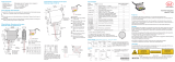
Fig. 1 True reproduction of the sensor with its actual location of the warning labels, ILD 2300

Page 16
Laser Class
optoNCDT 2300
optoNCDT
ERR
Power on
RUN
EtherCAT Ethernet
Laser off
In range
Midrange
Error
Laser spot
COMPLIES WITH 21 CFR 1040.10 AND 1040.11
EXCEPT FOR CONFORMANCE WITH
IEC 60825-1 ED. 3., AS DESCRIBED IN
LASER NOTICE NO. 56, DATED MAY 8, 2019
LASER RADIATION
Do not stare into beam
Class 2 Laser Product
IEC 60825-1: 2014
P 1mW; P 1.2mW; t=0.5...542 s
0 P
≤ ≤ μ
F=1.5...50kHz;
=405nm
Fig. 2 True reproduction of the sensor with its actual location of the warning labels, ILD2300-x BL
i
If both warning labels are covered over when the unit is installed the user must ensure that supplemen-
tary labels are applied.

Page 17
Functional Principle, Technical Data
optoNCDT 2300
3. Functional Principle, Technical Data
3.1 Short Description
The optoNCDT 2300 operates according to the principle of optical triangulation, i.e. a visible, modulated point
of light is projected onto the target surface. With diffuse arrangement, the sensor measures distances while
directly arranged the sensor measures distances or the thickness of a transparent measurement object.
Diffuse reflection Direct reflection
Sensor Distance Thickness
Sensor
ILD 2300
Measuring
range
SMR
Fig. 3 Definition of terms
Sensor
ILD 2300
Measuring
range
SMR
ILD 2300-2 • •
ILD 2300-5 • •
ILD 2300-10 • •
ILD 2300-20 • •
ILD 2300-50 •
ILD 2300-100 •
ILD 2300-200 •
ILD 2300-300
ILD2300-2LL •
ILD2300-10LL •
ILD2300-20LL •
ILD2300-50LL •
ILD2300-2BL •
ILD2300-5BL •
ILD2310-50BL •
ILD 2310-10 •
ILD 2310-20 •
ILD 2310-40 •
ILD 2310-50 •
ILD 2300 2DR • •

Page 18
Functional Principle, Technical Data
optoNCDT 2300
The diffuse element of the reflection of the light spot is imaged by a receiver optical element positioned at a
certain angle to the optical axis of the laser beam onto a high-sensitivity resolution element (CCD), in depen-
dency on displacement. From the output signal of the CCD element a digital signal processor (DSP) in the
sensor calculates the displacement between the light spot on the object being measured and the sensor. The
displacement is linearized and then issued via digital interfaces.
3.2 Real Time Control (A-RTSC)
The CMOS element determines the intensity of incident light during the exposure. This enables the sensor to
compensate for fluctuations in brightness on the object being measured. What is more, it does so in a range
from almost total absorption to almost total reflection. The new A-RTSC (Advanced Real-Time-Surface-Com-
pensation) is a development of approved RTSC and allows a more accurate real-time surface compensation
in the measurement process with a higher dynamic range.
3.3 Exposure Control
Dark or shining objects to be measured may require a longer exposure time. However, the sensor is not ca-
pable of providing exposure which is any longer than permitted by the measurement frequency. For a longer
exposure time, therefore, the measurement frequency of the sensor has to be reduced either manually or by
command, see Chap. 7.4.2.

Page 19
Functional Principle, Technical Data
optoNCDT 2300
3.4 Technical Data
ILD 2300-20
ILD 2310-20
ILD 2300-10
ILD 2310-10
ILD 2300-2DR
ILD 2300-2
ILD 2300-5
ILD 2300-200
ILD 2300-100
ILD 2300-50
ILD 2310-50
ILD 2310-40
Start of measuring range
Measuring range up to 30 kHz measuring rate
Measuring range 49.140 kHz measuring rate
100 mm 200 mm 300 mm 400 mm 500 mm 600 mm
ILD 2300-300
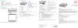
Fig. 4 Measuring ranges for displacement measurement in direct and diffuse reflection
1) 1. value: Measuring rate of 1.5 kHz up to 30 kHz. 2. value: Measuring rate 49.140 kHz.
2) At a measuring rate of 20 kHz, without averaging.
The specified data apply for a diffusely reflecting matt white ceramic target.
SMR = Start of measuring range; MMR = Midrange; EMR = End of measuring range

Page 20
Functional Principle, Technical Data
optoNCDT 2300
Type ILD 2300- 2 5 10 20 50 100 200 300
Measuring range
1
mm
2 / 2
(.08 / .08)
5 / 2
(.20 / .08)
10 / 5
(.39 / .20)
20 / 10
(.79 / .39)
50 / 25
(1.97 / .99)
100 / 50
(3.94 / 1.97)
200 / 100
(1.57 / 3.94)
300 / 150
(11.81 / 5.9)
Start of measuring range
1
mm
24 / 24
(.94 / .94)
24 / 24
(.94 / .94)
30 / 35
(1.18 / 1.38)
40 / 50
(1.57 / 1.97)
45 / 70
(1.77 / 2.76)
70 / 120
(2.76 / 4.72)
130 / 230
(5.12 / 9.06)
200 / 350
(1.57 / 13.78)
Midrange
1
mm
25 / 25
(.98 / .98)
26.5 / 25
(1.04 / .98)
35 / 37.5
(1.38 / 1.48)
50 / 55
(1.97 / 2.17)
70 / 82.5
(2.76 / 3.25)
120 / 145
(4.72 / 5.71)
230 / 280
(9.06 / 11.02)
350 / 425
(13.78 / 16.73)
End of measuring range
1
mm
26 / 26
(1.02 / 1.02)
29 / 26
(1.14 / 1.02)
40 / 40
(1.57 / 1.57)
60 / 60
(2.36 / 2.36)
95 / 95
(3.74 / 3.74)
170 / 170
(6.69 / 6.69)
330 / 330
(13.0 / 13.0)
500 / 500
(19.69 / 19.69)
Linearity
µm
0.6 1.5 2 4 10 30 60 90
Resolution (at 20 kHz)
2
µm
0.03 0.08 0.15 0.3 0.8 1.5 3 4.5
Measuring rate, programmable 49.140 / 30 / 20 / 10 / 5 / 2.5 / 1.5 kHz (49.140 kHz with reduced measuring range)
Light source (Laser diode) Wave length 670 nm, red, max. power 1 mW, laser class 2
Permissible ambient light 10,000 lx … 40,000 lx
Light spot diameter
(±10 %)
SMR, µm 55 x 85 70 x 80 75 x 85 140 x 200 255 x 350 350 1300 580 x 860
MR, µm 23 x 23 30 x 30 32 x 45 46 x 45 70 x 70 130 1300 380 x 380
EMR, µm 35 x 85 70 x 80 110 x 160 140 x 200 255 x 350 350 1300 470 x 530
Operating temperature 0 ... +50 °C (+32 °F up to +122 °F)
Storage temperature -20 ... +70 °C (-4 °F up to +158 °F)
Protection class IP 65 (with plugged connection)
Power supply U
B
24 VDC (11 ... 30 V); P < 3 W
Measurement value output
RS422, Ethernet, EtherCAT (selectable)
Synchronization programmable Simultaneous or alternating
Sensor cable (standard) 0.25 m (with cable jack)
Vibration (acc. to IEC 60068-2-6) 2 g / 20 ... 500 Hz
Shock (acc. to IEC 60068-2-29) 15 g / 6 ms / 3 axes
Housing size S M
Weight (with 25 cm cable) 550 g 550 g 600 g
1) 1. value: Measuring rate of 1.5 kHz up to 30 kHz. 2. value: Measuring rate 49.140 kHz, see Page 19
/