Page is loading ...

D
Fordern Sie weitere Informationen zur umfangreichen Produktpalette aus dem Hause
Dometic WAECO an. Bestellen Sie einfach unsere Kataloge kostenlos und unver-
bindlich unter der Internetadresse: www.dometic-waeco.de
GB
We will be happy to provide you with further information about Dometic WAECO
products. Please order our free catalogue with no obligation to buy on our homepage:
www.dometic-waeco.com
F
Demandez d’autres informations relatives à la large gamme de produits de la maison
Dometic WAECO. Commandez tout simplement notre catalogue gratuitement et sans
engagement à l’adresse internet suivante : www.dometic-waeco.com
E
Solicite más información sobre la amplia gama de productos de la empresa Dometic
WAECO. Solicite simplemente nuestros catálogos de forma gratuita y sin compromi-
so en la dirección de Internet: www.dometic-waeco.com
I
Per ottenere maggiori informazioni sull’ampia gamma di prodotti Dometic WAECO è
possibile ordinare una copia gratuita e non vincolante del nostro Catalogo all’indirizzo
Internet: www.dometic-waeco.com
NL
Maak kennis met het omvangrijke productscala van de firma Dometic WAECO. Bestel
onze catalogus gratis en vrijblijvend onder het internetadres:
www.dometic-waeco.com
DK
Bestil yderligere information om det omfattende produktudvalg fra Dometic WAECO.
Bestil vores katalog gratis og uforpligtende på internetadressen:
www.dometic-waeco.com
S
Inhämta mer information om den omfattande produktpaletten från Dometic WAECO:
Beställ våra kataloger gratis och utan förpliktelser under vår Internetadress:
www.dometic-waeco.com
N
Be om mer informasjon om det rikholdige produktutvalget fra Dometic WAECO.
Bestill vår katalog gratis uforbindtlig på Internettadressen: www.dometic-waeco.com
FIN
Pyytäkää lisää tietoja Dometic WAECOn kattavista tuotevalikoimista. Tilatkaa tuoteku-
vastomme maksutta ja sitoumuksetta internet-osoitteesta: www.dometic-waeco.com

PerfectPower
3
GRID
AC INPUT
CIRCUIT
BREAKER
AC INPUT
230V AC
OUTPUT
POWER
OLP
OVP
UVP
321 4
5
6
7
8
1
DC INPUT
NEG– POS+
REVERSE POLARITY
WILL DAMAGE UNIT
AB
ON
REMO.
OFF
123 4 675
2
A
B
3

PerfectPower
4
FG
J3
N + FG
FG
J3
N + FG
1
22
PP1000 PP2000
3
4
5
3
4
5
4
Status
Power
Level
Loa
d
Level
Input
On
Off
1.
2.
5

PerfectPower
5
Input
230 V AC
Output
230 V AC
N
PerfectPower
DC
Input
DC
230 V AC
FI 2
RCD
FI 1
RCD
PE
L1
N
PE
L1
N
PE
L!
N
PE
L1
654
1
3
7
2
6

EN
PerfectPower
24
Please read this instruction manual carefully before starting the
appliance and keep it in a safe place for future reference. If you pass on
the device to another person, hand over this operating manual along
with it.
Table of contents
1 Explanation of symbols . . . . . . . . . . . . . . . . . . . . . . . . . . . . . . . . . . 25
2 General safety instructions . . . . . . . . . . . . . . . . . . . . . . . . . . . . . . . 25
3 Scope of delivery . . . . . . . . . . . . . . . . . . . . . . . . . . . . . . . . . . . . . . . 27
4 Accessories . . . . . . . . . . . . . . . . . . . . . . . . . . . . . . . . . . . . . . . . . . . 27
5 Target group for this manual . . . . . . . . . . . . . . . . . . . . . . . . . . . . . . 27
6 Intended use . . . . . . . . . . . . . . . . . . . . . . . . . . . . . . . . . . . . . . . . . . 28
7 Technical description . . . . . . . . . . . . . . . . . . . . . . . . . . . . . . . . . . . . 28
8 Fastening and connecting the inverter. . . . . . . . . . . . . . . . . . . . . . . 31
9 Using the inverter. . . . . . . . . . . . . . . . . . . . . . . . . . . . . . . . . . . . . . . 36
10 Cleaning and caring for the inverter. . . . . . . . . . . . . . . . . . . . . . . . . 37
11 Rectifying faults . . . . . . . . . . . . . . . . . . . . . . . . . . . . . . . . . . . . . . . . 38
12 Guarantee . . . . . . . . . . . . . . . . . . . . . . . . . . . . . . . . . . . . . . . . . . . . 39
13 Disposal . . . . . . . . . . . . . . . . . . . . . . . . . . . . . . . . . . . . . . . . . . . . . . 39
14 Technical data . . . . . . . . . . . . . . . . . . . . . . . . . . . . . . . . . . . . . . . . . 40

EN
PerfectPower Explanation of symbols
25
1 Explanation of symbols
!
WARNING!
Safety instruction: Failure to observe this instruction can cause
fatal or serious injury.
A
NOTICE!
Failure to observe this instruction can cause material damage and
impair the function of the product.
I
NOTE
Supplementary information for operating the product.
➤ Action: This symbol indicates that action is required on your part. The
required action is described step-by-step.
✓ This symbol describes the result of an action.
fig. 1 5, page 3: This refers to an element in an illustration. In this case,
item 5 in figure 1 on page 3.
2 General safety instructions
The manufacturer accepts no liability for damage in the following cases:
Faulty assembly or connection
Damage to the product resulting from mechanical influences and excess
voltage
Alterations to the product without express permission from the
manufacturer
Use for purposes other than those described in the operating manual
2.1 General safety
!
WARNING!
Use the device only as intended.
Maintenance and repair work may only be carried out by quali-
fied personnel who are familiar with the risks involved and the
relevant regulations.

EN
General safety instructions PerfectPower
26
People (including children) whose physical, sensory or mental
capacities or whose lack of experience or knowledge prevent
them from using this product safely should not use it without the
supervision or instruction of a responsible person.
Electrical devices are not toys!
Always keep and use the device well out of the reach of chil-
dren.
2.2 Safety when installing the device
!
WARNING!
Installing the device may only be performed by qualified person-
nel who are familiar with the guidelines and safety precautions
to be applied.
If electrical devices are incorrectly installed on boats, corrosion
damage might occur. The device should be installed by a spe-
cialist (marine) electrician.
2.3 Operating the device safely
!
WARNING!
Note the following basic safety information when using electrical
devices to protect against:
Electric shock
Fire hazards
Injury
Operate the device only if you are certain that the housing and
the cables are undamaged.
Make sure the air inlets and outlets of the device are not cov-
ered.
Ensure good ventilation. The inverter produces dissipated heat
which has to be diverted.
Always disconnect the power supply when working on the de-
vice.

EN
PerfectPower Scope of delivery
27
3 Scope of delivery
4 Accessories
Available as accessories (not included in the scope of delivery):
If you have questions in respect of the accessories, please contact your local
service partner.
5 Target group for this manual
The “Connecting the inverter” on page 32 is solely intended for qualified
professionals who are familiar with the relevant VDE (German Engineering
Society) regulations!
All other chapters are intended for the users.
Quantity Designation
1 Inverter
1 230 V connection cable
4 Mounting brackets
1 Mounting plate
2 Cable terminal
1 Operating manual
Description Item number
Remote control MCR-9 MCR-9

EN
Intended use PerfectPower
28
6 Intended use
!
WARNING!
Never use the inverter on vehicles where the positive terminal of
the battery is connected to the chassis.
Inverters PP1002, PP1004, PP2002 and PP2004 are used for supplying
power to 230 V consumers with a 12 V or 24 V power supply:
12 V: PP1002 and PP2002
24 V: PP1004 and PP2004
The inverters are suitable for use in caravans, commercial vehicles and
motor and sailing vessels.
7 Technical description
Inverters PP1000 and PP2000 consist of two function units:
Inverter switch: generates 230 V AC power from a battery voltage of
– 12 V: PP1002 and PP2002
– 24 V: PP1004 and PP2004
Mains priority circuit: switches automatically between 230 V of external
mains voltage (e.g. on a camping site) and a battery generated 230 V
power supply
The external supply has priority. If no more external voltage is available,
the output socket is disconnected from the external power supply and
connected to the inverter voltage. This ensures that the output socket
always has a power supply of 230 V.
From inverter operation to mains power supply:
There is a delay when switching from inverter operation (whereby the
230 V AC power is produced from the battery voltage) to the mains
power supply.
When the plug is inserted in the outside socket (camping site, harbour)
the inverter is switched off after a delay of approx. 4 s. After a further 2 s,
the mains power supply is switched through. This gives the devices
connected enough time to switch off properly.
From mains power to inverter operation:
A delay also occurs when switching from mains power to inverter
operation.

EN
PerfectPower Technical description
29
If the mains supply fails, the inverter switches on after 2 seconds.
A
NOTICE!
When switching over, any devices connected should be switched
off. Because they do not receive voltage for 2 s, they may have to
be switched back on.
The inverter is equipped with protection against thermal and electrical
overloading, as well as excess and insufficient voltage. The inverter switches
off:
If its internal temperature is too high
If the load exceeds the values listed in the technical data
If the input voltage is too high or too low
A single consumer or a socket distribution system can be connected to the
inverter to create an on-board 230 V supply with several sockets.
The device is equipped at delivery with galvanic isolation. For the safe
operation of multiple consumers, it is essential that a circuit breaker (residual
current circuit breaker) is built into the socket distribution circuit and the
grounding bridge is set in the inverter.
I
NOTE
Note when connecting devices with an electrical drive (such as
power drills and refrigerators), that they often need more power
than is stated on the type plate.
The inverter can be switched on manually or using a remote control.
Cooling is provided by a fan and is load-dependent.

EN
Technical description PerfectPower
30
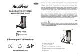
7.1 Control elements
Front view (fig. 1, page 3):
Rear view (fig. 2, page 3):
No. Description
1 Grid: This LED lights up if the inverter is supplied with external 230 V
mains power; the priority circuit is active.
2 Connection for the external 230 V power supply
3 Circuit breaker: Fuse
4 230 V AC output
5 POWER: This LED lights up when the inverter is switched on.
6 OLP: This LED lights up when the consumers connected draw too
much electricity.
7 UVP: This LED lights up when battery capacity is too weak.
8 OVP: This LED lights up when the input voltage is too high.
No. Description
1 Main switch
2 Connection for MCR-9 remote control
3 Connection for an external switch contact
4 Earth connection
5Fan
6 Negative terminal
7 Positive terminal

EN
PerfectPower Fastening and connecting the inverter
31
8 Fastening and connecting the inverter
8.1 Fastening the inverter
You can fasten the inverter using the holders supplied.
Note the following safety instructions during installation:
!
WARNING!
Ensure the device is standing firmly.
Set up the device securely and fasten it in such a way that
– it cannot tip over or fall down
– it cannot move while the vehicle is in motion
Take precautions necessary to ensure that it is out of reach of
children. Dangerous situations may occur which cannot be rec-
ognised by children!
When selecting the installation location, observe the following instructions:
Do not operate the device
– in wet or damp environments
– in dusty environments
– in the vicinity of flammable materials
– in spaces where there is a danger of explosion
Do not expose the device to a heat source (such as direct sunlight or
heating). Avoid additional heating of the device in this way.
Make sure the cables are the correct length and choose the installation
location near the battery supply.
Select a well-ventilated location for the device.
A ventilation system must be present for installations in small, enclosed
spaces.
Make sure that the air intake on the front of the inverter remains clear.
Select a mounting surface which is flat and sufficiently firm.

EN
Fastening and connecting the inverter PerfectPower
32
Fasten the inverter as follows (fig. 5, page 4):
A
NOTICE!
Before drilling any holes, make sure that no electrical cables or oth-
er parts of the vehicle can be damaged by drilling, sawing and filing.
➤ Clip two holders on the left bar and two on the lower right bar.
You can move the holders as required.
➤ Fasten the inverter by screwing one screw through each hole in the
holder.
8.2 Connecting the inverter
!
WARNING!
The inverter may only be connected by a qualified workshop.
The following information is intended for specialists who are famil-
iar with the guidelines and safety precautions to be applied.
Observe the following safety instructions for the electrical connections:
A
NOTICE!
Caution – Risk of short circuit!
When working on the vehicle, always disconnect the earth
connection to the supply battery.
Disconnect the 230 V external power supply to the caravan.
If you have to feed cables through metal walls or other walls with
sharp edges, use ducts or tubes to prevent damage.
Do not lay cables which are loose or bent next to electrically
conductive material (metal).
Fasten the cables securely.
Do not pull on the cables.
Do not lay the 230 V mains cable and the 12/24 V DC cable in
the same duct.
Lay the cables so that they cannot be tripped over or damaged.

EN
PerfectPower Fastening and connecting the inverter
33
!
WARNING! Danger of electrocution!
If you wish to connect more than one consumer to the inverter and
install a socket distributor loop, you must arrange a circuit breaker
(residual current circuit breaker) and set a grounding bridge in the
inverter, see “Connecting multiple consumers” on page 34.
Earthing the inverter
➤ Connect the earth connection on the inverter (fig. 2 4, page 3) with the
earth of the vehicle.
Connecting the inverter to the battery
I
NOTE
Please be aware that all volatile memories of the connected electric
consumers will lose their stored data if the battery is disconnected.
A
NOTICE!
Make sure the polarity is correct. If the positive and negative con-
nections are reversed, this may damage the device.
➤ Connect the terminal on the red battery connection cable to the positive
terminal (fig. 2 7, page 3) on the inverter.
➤ Connect the terminal on the black battery connection cable to the
negative terminal (fig. 2 6, page 3) on the inverter.
➤ Check the connections are secure.
You might have to tighten the screws again later.
I
NOTE
Sparks may be produced when the connections are made due to
the internal capacitors being charged.
➤ Connect the red battery connection cable to the positive terminal on the
battery.
➤ Connect the black battery connection cable to the negative terminal on
the battery.

EN
Fastening and connecting the inverter PerfectPower
34
Connecting the inverter to the 230 V mains supply
➤ Plug the 230 V connection cable into the connector for the 230 V power
supply to the inverter (fig. 1 2, page 3).
➤ Connect the 230 V connection cable to a 230 V socket in the vehicle.
Connecting the remote control to the inverter
➤ Switch off the inverter.
➤ Insert the cable end of the remote control into the connection (fig. 2 2,
page 3).
➤ Set the main switch (fig. 2 1, page 3) to “Remote”.
Connecting the external switch contact to the inverter
➤ Switch off the inverter.
➤ Connect the external switch contact (power supply from the inverter) at
the remote port (fig. 2 3, page 3) in accordance with the wiring diagram
(fig. 3, page 3),
➤ Set the main switch (fig. 2 1, page 3) to “Remote”.
I
NOTE
If you wish to use an external switch contact with a power supply of
it own, e.g. the ignition, you must interconnect a suitable relay.
8.3 Connecting multiple consumers
!
WARNING! Danger of electrocution!
If you wish to connect more than one consumer to the inverter and
install a socket distribution circuit, you must arrange a circuit break-
er (residual current circuit breaker) and set a grounding bridge in
the inverter. The grounding bridge may only be connected by a
trained professional who is familiar with the relevant VDE (German
Engineering Society) regulations.
The device is equipped at delivery with galvanic isolation. For the safe
operation of multiple consumers, it is essential that a circuit breaker (residual
current circuit breaker) is built into the socket distribution circuit, see sample
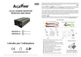
circuit diagram in fig. 6, page 5.

EN
PerfectPower Fastening and connecting the inverter
35
Sample circuit diagram legend:
➤ Install a residual current circuit breaker in the socket distribution circuit.
Setting grounding bridge (fig. 4, page 4)
!
WARNING! Danger of electrocution!
The grounding bridge may only be connected by a trained profes-
sional who is familiar with the relevant VDE (German Engineering
Society) regulations.
I
NOTE
The grounding bridge plug is always plugged into socket “FG”
(insulated AC current) when delivered.
➤ Unscrew the top four fastening screws (2) on the front of the device with
a hex key.
➤ Take off the cover (1).
A
NOTICE!
The grounding bridge is changed with sockets “FG” and “N + FG”.
Do not alter the other sockets, otherwise the device may be dam-
aged.
➤ Remove the plug (3) from socket “FG” (4).
➤ Insert the plug (3) into socket “N + FG” (5).
➤ Replace the device cover (1) and fix using the screws (2).
No. in fig. 6,
page 5
Explanation
1 230 V
AC
power source
2 Additional devices, e.g. battery charger, refrigerator
3 DC power source (battery)
4Inverter
5 Grounding bridge set
(At delivery: not set, shown by dotted line)
6 Circuit breaker (residual current circuit breaker)
7 Socket distribution circuit for consumers

EN
Using the inverter PerfectPower
36
9 Using the inverter
A
NOTICE!
If no circuit breaker is present: If the inverter is connected to the
external mains voltage, the 230 V output socket is earthed.
If there is no external mains voltage, the inverter is only connected
to the battery (DC operation). In this case, the 230 V output socket
is not earthed, but safeguarded with the protective insulation in-
stead.
A
NOTICE! Risk of short circuit!
You must switch on the inverter first before switching on the con-
sumers.
When using the inverter, observe the following instructions:
If the battery voltage drops below the alarm value during operation (see
“Low voltage alarm” in “Technical data” on page 40), a warning signal
sounds and LED “UVP” (fig. 1 7, page 3) lights up.
If the battery voltage drops below the shutdown value (See “Low voltage
shutdown” in “Technical data” on page 40), the inverter switches off.
If the inverter overheats, it switches off and LED “OLP” (fig. 1 6, page 3)
lights up.
After it cools down, the inverter automatically switches back on.
When operating the inverter at a high load for lengthy periods, it is
advisable to start the engine in order to recharge the vehicle battery.
➤ Connect your consumer to the 230 V output (fig. 1 4, page 3).
You can also connect a socket distribution system.

EN
PerfectPower Cleaning and caring for the inverter
37
9.1 Using the inverter without remote control
➤ Set the main switch (fig. 2 1, page 3) to
– “ON” to switch the inverter on
– “OFF” to switch the inverter off
✓ LED “POWER” lights up when the inverter is switched on.
9.2 Using the inverter with a remote control
I
NOTE
Refer to the operating instructions of the remote control which are
also included in the scope of delivery.
➤ Set the main switch (fig. 2 1, page 3) to “Remote”.
➤ Switch the inverter on or off using
– the buttons on the remote control or
– the external switch contact
✓ LED “POWER” lights up when the inverter is switched on.
10 Cleaning and caring for the inverter
A
NOTICE!
Do not use sharp or hard objects or cleaning agents for cleaning as
these may damage the product.
➤ Occasionally clean the product with a damp cloth.

EN
Rectifying faults PerfectPower
38
11 Rectifying faults
I
NOTE
The output voltage can only be measured correctly with a True-
RMS measuring device.
Fault Cause Remedy
No output voltage No contact to the battery Check contact and cable.
Switch on the ignition if
necessary.
Overheating Switch off the consumer.
Let the inverter cool down
and ensure better ventilation.
If necessary, reduce the
constant load.
Input voltage too high Check the input voltage on
the inverter and compare with
the technical data for the
inverter.
Defective fuse (in the inverter
or the vehicle)
Replace the fuse with one of
the same specifications.
Defective device Replace the device.
The device switches on and
off repeatedly
Excessive constant load Reduce the load.
The inverter switches off
when the consumers are
switched on
Starting current too high Compare consumer power
with the maximum power
from the inverter.
The output voltage is too low Battery voltage is lower than
shutdown value (see “Low
voltage shutdown” in
“Technical data” on page 40)
Charge the battery (start the
engine).

EN
PerfectPower Guarantee
39
12 Guarantee
The statutory warranty period applies. If the product is defective, please
contact the manufacturer's branch in your country (see the back of the
instruction manual for the addresses) or your retailer.
For repair and guarantee processing, please include the following docu-
ments when you send in the device:
A copy of the receipt with purchasing date
A reason for the claim or description of the fault
13 Disposal
➤ Place the packaging material in the appropriate recycling waste bins
wherever possible.
M
If you wish to finally dispose of the product, ask your local recycling
centre or specialist dealer for details about how to do this in
accordance with the applicable disposal regulations.
/