Page is loading ...

DC/AC POWER INVERTER
MODIFIED SINE WAVE
Libretto per l’utilizzatore
www.alcapower.com
AlcaPower - Power Inverter 3000W - Libretto per l’utilizzatore V1 R3 [08/03/2018] © Tutti i diritti sono riservati Pag. 1
IRS3000-12
IRS3000-24
Grazie per aver scelto un prodotto AlcaPower. Potete essere certi che il prodotto da voi acquistato è tra i
migliori attualmente disponibili sul mercato. Per favore, prima di utilizzare il prodotto, leggete questo manuale
molto attentamente e conservatelo per consultazioni future.
AlcaPower IRS3000-12 e IRS3000-24 sono soft start power inverter, ovvero dispositivi che trasformano una
tensione continua a 12V (IRS3000-12) oppure a 24V (IRS3000-24), tipicamente fornita da uno o più accumu-
latori, in una tensione alternata a 220V AC 50Hz adatta ad alimentare svariati dispositivi elettrici.
I power inverter AlcaPower sono prodotti costruiti con componenti e circuiti all’avanguardia che ne garantisco-
no l’alta qualità, il peso e le dimensioni ridotte. Sono robusti e dotati di circuiti di protezione contro il sovrac-
carico in uscita, il surriscaldamento, il cortocircuito in uscita e la sovratensione in ingresso. Nonostante ciò,
per garantirne il buon funzionamento ed evitare danni al power inverter, ai dispositivi collegati e alle persone
è necessario provvedere ad un’installazione adeguata ed eseguita a regola d’arte.
ATTENZIONE:
Secondo la normativa IEC 60479-1, quando si opera con tensioni alternate (AC) uguali o maggiori di 50 Volt
l’energia elettrica nei conduttori della linea tensione alternata è da considerarsi potenzialmente letale!
AlcaPower - Power Inverter 3000W - Libretto per l’utilizzatore V1 R3 [08/03/2018] © Tutti i diritti sono riservati Pag. 2
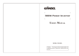
CAVI IN DOTAZIONE
Morsetti d’ingresso polo positivo (+) (rosso).
Interruttore ON/OFF.
Presa d’uscita USB 5V DC, max 500mA.
1
2
Morsetti d’ingresso polo negativo (-) (nero).
3
Ventola di rareddamento.
4
Morsetto per la messa a terra della carcassa.
5
LED verde (inverter acceso).
6
LED rosso (anomalia di funzionamento).
7
8
9
Presa d’uscita 220V AC.
E8
10R-04 12104
E8
10R-04 12105
Cavi connessione batteria
Cavo connessione morsetto di terra
1
2
3
4
5
6
7
8
9
10
10
Porta d’ingresso per controllo remoto.
11
11
Controllo remoto (accessorio opzionale).
912005 RC12V-S (IRS3000-12)
924005 RC24V-S (IRS3000-24)
Codice prodotto AlcaPower:
Accessorio opzionale
IT
ITALIANO

MESSA A TERRA E DISPOSITIVI ELETTRICI COLLEGABILI
Per garantire la massima sicurezza e le funzionalità del power inverter è necessario mettere a terra la car-
cassa metallica di quest’ultimo. A tal ne, il power inverter è dotato di un morsetto di messa a terra nella parte
posteriore
4
.
Nota. Il polo negativo delle batterie dev’essere connesso alla terra (vedi Norma CEI EN50272-2).
Nota. La messa a terra deve essere eseguita a regola d’arte secondo le normative vigenti. Per questo moti-
vo si consiglia di adare l’installazione dell’inverter a personale tecnico qualicato.
Se il dispositivo elettrico da collegare all’inverter è un dispositivo in Classe II, ovvero un dispositivo dotato di doppio
isolamento e senza la connessione della messa a terra, è possibile collegarlo all’inverter senza ulteriori accorgi-
menti. Questi dispositivi hanno di solito una spina a due poli e il simbolo del doppio isolamento sulla targa/etichetta
dati del prodotto.
Se il dispositivo elettrico da collegare all’inverter è un dispositivo in Classe I, ovvero un dispositivo con singolo
isolamento e con conduttore di messa a terra, per garantire la massima sicurezza è obbligatorio eseguire
la messa a terra del dispositivo elettrico seguendo le normative vigenti. E’ bene adare l’installazione della
messa a terra a personale tecnico specializzato.
Nota. Il polo di terra della presa d’uscita dell’inverter non è collegato alla carcassa metallica di quest’ultimo.
Quindi la semplice messa a terra della carcassa dell’inverter non è suciente per eettuare la messa a terra
del dispositivo elettrico da collegare all’inverter.
UTILIZZO DEL POWER INVERTER
Per garantire la massima sicurezza e adabilità, dopo aver eseguito la messa a terra come descritto nella
sezione MESSA A TERRA E DISPOSITIVI ELETTRICI COLLEGABILI, si consiglia di collegare prima l’inver-
ter alle batterie, dopo accendere l’inverter, dopo ancora collegare il vostro dispositivo elettrico e accenderlo
seguendo le istruzioni seguenti.
1. Collegare i cavi rossi ai morsetti d’ingresso rossi dell’ inverter, polo positivo (+)
3
. Collegare i cavi
neri ai morsetti d’ingresso neri dell’inverter, polo negativo (-)
1
. Non invertire la polarità, si rischia il
danneggiamento dell’inverter.
2. Collegare i cavi rossi al polo positivo (+) della batteria / delle batterie. Collegare i cavi neri al polo negati-
vo (-) della batteria / delle batterie. Non invertire la polarità, si rischia il danneggiamento dell’inverter.
3. Accendere l’inverter tramite l’interruttore ON/OFF . Se non ci sono anomalie di funzionamento il
LED verde
5
si illumina e il LED rosso
6
rimane spento.
4. Collegare il vostro dispositivo elettrico alla presa d’uscita dell’inverter .
5. Accendere il vostro dispositivo elettrico.
Nota. Non connettere o sconnettere l’inverter dalle batterie quando è accesso, ovvero quando l’interruttore
10
è nella posizione ON.
Nota. Oltre che tramite l’interruttore ON/OFF, il power inverter può essere acceso e spento con il controllo
remoto collegabile all’apposita porta d’ingresso
9
posta sul frontalino dell’inverter. Questo accessorio è
opzionabile, vedi pagina 2.
Nota. Nel momento in cui si collegano i cavi dell’inverter alla batteria può succedere che si generino delle scin-
tille tra uno dei cavi e la batteria. Questo evento è normale ed è causato dalla carica dei condensatori d’ingresso
dell’inverter.
Simbolo doppio isolamento
AlcaPower - Power Inverter 3000W - Libretto per l’utilizzatore V1 R3 [08/03/2018] © Tutti i diritti sono riservati Pag. 3 AlcaPower - Power Inverter 3000W - Libretto per l’utilizzatore V1 R3 [08/03/2018] © Tutti i diritti sono riservati Pag. 4
ESTENSIONE DEI CAVI
In generale, l’allungamento dei cavi di collegamento tra la batteria e l’ingresso del power inverter può provo-
care una caduta di tensione con la conseguente riduzione della potenza che l’inverter può fornire in uscita.
Se necessario si consiglia di allungare solo il cavo (o i cavi) che collega l’uscita dell’inverter con l’apparecchio
che intendete alimentare. In ogni caso è vietato tagliare, modicare o manomettere i cavi in dotazione, pena
la perdita di ogni diritto di garanzia.
Nell’eventualità che sia abbia la necessità di utilizzare collegamenti più lunghi tra la batteria e l’inverter, si
possono utilizzare cavi con le caratteristiche riportate nella tabella sottostante.
Modello
Lunghezza massima
del cavo
Diametro minimo del
cavo
Sezione minima del
cavo
IRS3000-12 1 metro 7.35mm (1 AWG) 42.4mm
2
(1 AWG)
IRS3000-24 1 metro 6.54mm (2 AWG) 33.6mm
2
(2 AWG)
FUNZIONI DI PROTEZIONE
Se all’accensione dell’inverter o all’accensione del dispositivo elettrico collegato il LED di colore rosso si
illumina, signica che si è vericato una anomalia e l’inverter ha attivato una o più funzioni di protezione.
In questo caso è necessario spegnere l’inverter, scollegarlo dalle batterie e scollegare il vostro dispositivo
dall’inverter. Prima di ricollegare l’inverter e il vostro dispositivo accertarsi di aver risolto i problemi che hanno
provocato l’entrata in funzione delle protezioni. Fare riferimento alla Tabella 1 per la verica e la risoluzione
dei problemi più comuni.
Il power inverter, oltre al LED rosso, è dotato di avvisatore acustico che entra in funzione quando la tensione
d’ingresso all’inverter è inferiore a 10.5V DC (IRS3000-12), oppure a 21V DC (IRS3000-24).
Il power inverter è dotato delle seguenti protezioni che, in caso di problemi, disattivano l’uscita 220V AC.
• Bassa tensione in ingresso: questa protezione entra in funzione quando la tensione d’ingresso è infe-
riore a 9.5V DC (IRS3000-12), 19V DC (IRS3000-24).
• Sovratensione in ingresso: questa protezione entra in funzione quando la tensione in ingresso al power
inverter è superiore a 15V DC (IRS3000-12), 30V DC (IRS3000-24).
• Sovraccarico in uscita: questa protezione entra in funzione quando la potenza richiesta all’inverter è
superiore a 3000W.
• Cortocircuito temporaneo in ingresso: questa protezione entra in funzione quando i terminali d‘ingresso
dell’inverter sono cortocircuitati. Rimuovere velocemente il cortocircuito per evitare pericoli o danni
all’inverter.
• Cortocircuito temporaneo in uscita: questa protezione entra in funzione quando la spina d’uscita è mes-
sa in cortocircuito. Rimuovere velocemente il cortocircuito per evitare pericoli o danni all’inverter.
• Temperatura eccessiva: questa protezione entra in funzione quando i circuiti interni dell’inverter si
surriscaldano. Questa protezione attiva anche l’avvisatore acustico.
Nota. Una temperatura eccessiva all’interno dell’inverter può essere causata dall’esposizione dell’inverter al
sole, oppure il suo posizionamento in un luogo che ne impedisce una ventilazione ecace.
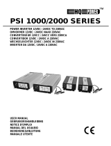
VENTILAZIONE
Per permettere un deusso ecace del calore
emesso è necessario che il power inverter sia
posizionato in modo che la ventola di raredda-
mento svolga correttamente la propria funzio-
ne. Vedere la gura qui a anco.
6
7
10
7
IT
IT

MISURA DELLA TENSIONE AC IN USCITA
Il power inverter fornisce all’uscita AC una tensione con una forma d’onda sinusoidale modicata. I comuni
voltmetri/multimetri che si trovano in commercio sono adatti solo alla misura di tensioni sinusoidali pure e
pertanto non sono adatti alla misura del valore ecace (RMS) della tensione d’uscita del power inverter.
Tipicamente, i comuni multimetri forniscono una misura della tensione d’uscita inferiore di 20 o 30V rispetto al
vero valore ecace. Pertanto, per misurare il valore ecace è necessario utilizzare un voltmetro o un multi-
metro in grado di misurare il valore ecace di forme d’onda non sinusoidali pure.
PRECAUZIONI E AVVERTIMENTI
• Per evitare danni, all’accensione o allo spegnimento del motore del vostro veicolo l’inverter deve essere
spento.
• Per evitare danni all’inverter scollegarlo dalle batterie quando si procede alla ricarica con un caricabatterie.
• Per evitare di scaricare la batteria si consiglia di tenere accesso il motore del vostro veicolo quando
l’inverter è in funzione.
• Assicurarsi che la tensione delle batterie non ecceda i limiti massimi consentiti.
• Prima di eseguire i collegamenti assicurarsi che l’inverter e i dispositivi elettrici da collegare siano spenti.
• Se l’inverter attiva l’allarme sonoro, che segnala una bassa tensione in ingresso, scollegare l’inverter e
procedere alla ricarica delle batterie. In ogni caso, per non scaricare completamente le batterie, l’inverter
si spegne automaticamente quando la tensione d’ingresso scende sotto i 9.5V DC (IRS3000-12), oppure
i 19V DC (IRS3000-24) (vedi Tabella 1 e CARATTERISTICHE TECNICHE).
• Alcune apparecchiature, come ad esempio strumenti di misura, alimentatori switching dotati di circuito
PFC e strumenti di precisione, potrebbero non funzionare con l’onda sinusoidale modicata. In questi
casi si consiglia l’utilizzo di un inverter ad onda sinusoidale pura.
• All’interno dell’inverter non ci sono parti da sottoporre a manutenzione da parte dell’utente.
• Tenere pulite da polvere e sporco le parti esterne dell’inverter, in particolar modo le feritoie d’areazione
della ventola di rareddamento.
• Assicurarsi che l’inverter sia ben ventilato, non ostruire i buchi per la ventilazione posti sulla carcassa ne
i buchi relativi alle ventole di rareddamento.
• Per evitare pericoli di shock elettrico non utilizzare l’inverter con le mani bagnate.
• Per evitare pericoli di shock elettrico o possibili ferite, tenere l’inverter lontano dalla portata dei bambini
e dalle persone non autosucienti.
• Per evitare pericoli di shock elettrico utilizzare l’inverter in un luogo asciutto e al coperto, lontano da
acqua e qualunque altro genere di liquido.
• Non tentare di aprire l’inverter ne tentare di introdurvi oggetti o materiali di qualunque genere.
• Qualsiasi modica all’inverter può generare pericoli e cancella ogni diritto di garanzia.
• Quando necessario, sostituire i fusibili dell’inverter con fusibili aventi le medesime caratteristiche.
• Non tentare di accedere all’interno dell’inverter, ci sono tensioni e correnti potenzialmente letali.
• Per non danneggiare l’inverter e rischiare la folgorazione non tentare di collegare fonti di energia a
220V AC all’inverter.
AlcaPower - Power Inverter 3000W - Libretto per l’utilizzatore V1 R3 [08/03/2018] © Tutti i diritti sono riservati Pag. 5
Funzione di
protezione
Stato dell’inverter
Ripristino del funzio-
namento regolare
Luci LED Allarme sonoro
Uscita
220V AC
Allarme bassa
tensione in
ingresso
LED verde ON
LED rosso OFF Attivo Attiva
Quando la tensione di bat-
teria in ingresso supera di
nuovo 10.5V (IRS3000-12),
21V (IRS3000-24), l’allar-
me si disattiva.
Spegnimento
causa bassa
tensione in
ingresso
LED verde ON
LED rosso ON
Attivo Disattiva
Quando la tensione di batte-
ria in ingresso ritorna sopra
la soglia di spegnimento
l’inverter riattiva l’uscita AC.
LED verde ON,
LED rosso OFF.
Spegnimento
causa sovra-
tensione in
ingresso
LED verde ON
LED rosso ON
Disattivo Disattiva
Quando la tensione di bat-
teria in ingresso torna sotto
i 15V (IRS3000-12), i 30V
(IRS3000-24), l’inverter riat-
tiva l’uscita AC.
LED verde ON,
LED rosso OFF.
Spegnimento
causa sovrac-
carico in uscita
LED verde ON
LED rosso ON
Disattivo Disattiva
Se viene ridotto il carico in
uscita ad un valore non su-
periore ai 3000W l’inverter
riattiva l’uscita AC.
LED verde ON,
LED rosso OFF.
Spegnimento
causa sovra-
temperatura
LED verde ON
LED rosso ON
Attivo Disattiva
Quando la temperatura dei
circuiti elettronici scende
sotto la soglia d’allarme
l’inverter riattiva l’uscita AC.
LED verde ON,
LED rosso OFF.
Spegnimento
causa cor-
tocircuito in
uscita
LED verde ON
LED rosso OFF
Disattivo Disattiva
Quando il cortocircuito vie-
ne rimosso l’inverter riattiva
l’uscita AC.
Nota: la porta USB continua a funzionare regolarmente anche quando viene attivata una delle funzioni di
protezione.
Tabella 1
AlcaPower - Power Inverter 3000W - Libretto per l’utilizzatore V1 R3 [08/03/2018] © Tutti i diritti sono riservati Pag. 6
7
IT
IT

• Non utilizzare l’inverter nelle vicinanze di materiali e gas inammabili.
• Dopo un utilizzo prolungato la temperatura della carcassa può essere elevata, perciò non toccare
l’inverter se si è scaldato.
• Non collegare dispositivi alla porta USB dell’inverter che richiedono un corrente maggiore di quella
massima erogabile dalla porta, si rischia la distruzione della porta USB.
• In caso di dubbi, malfunzionamenti o rotture contattare il rivenditore presso il quale si è acquistato
l’inverter.
FUNZIONAMENTO VENTOLE DI RAFFREDDAMENTO
Per risparmiare energia, le ventole di rareddamento entrano in funzione quando la potenza erogata dall’in-
verter supera il 30% della potenza massima, oppure quando la temperatura interna supera i 60°C.
AlcaPower - Power Inverter 3000W - Libretto per l’utilizzatore V1 R3 [08/03/2018] © Tutti i diritti sono riservati Pag. 7 AlcaPower - Power Inverter 3000W - Libretto per l’utilizzatore V1 R3 [08/03/2018] © Tutti i diritti sono riservati Pag. 8
Modello IRS3000-12 IRS3000-24
Tensione d’ingresso 11-15V DC 22-30V DC
Tensione d’uscita 230V AC ± 10%, 50Hz ± 3Hz
Uscita USB 5V DC, 500mA max
Potenza d’uscita 3000W
Potenza di spunto 6000W
Forma d’onda in uscita Sinusoidale modicata
Ecienza >80%
Consumo a vuoto < 0.6A < 0.5A
Tensione d’allarme batteria
scarica
10.5V DC ± 0.3V 21V DC ± 0.6V
Tensione di spegnimento
automatico
9.5V DC ± 0.3V 19V DC ± 0.6V
Tensione oltre la quale si ha
lo spegnimento automatico
15V ~ 16V DC 30V ~ 32V DC
Fusibile 12 da 30A 12 da 15A
Temperatura ottimale di lavoro
Da 5°C a 35°C
Grado di protezione
IP20
Dimensioni 380x215x100mm
Peso circa 6085gr
CARATTERISTICHE TECNICHE
Nota: le immagini di questo libretto sono solo per riferimento, non sono contrattuali e
possono dierire dal prodotto reale.
IT
AVVERTIMENTI
L’energia elerica è fonte di pericoli
Prima di ulizzare questo prodoo assicuratevi che l’uso del
medesimo avvenga nel rispeo delle disposizioni di legge ae-
ren la vostra ed altrui salute e sicurezza. Perciò è necessario
ulizzare il prodoo secondo le regole, norme e disposizioni
valide in materia di tutela della vostra salute e sicurezza, se-
condo le istruzioni, nella piena conformità delle condizioni pre-
scrie in questa pubblicazione.
Persone inesperte, inconsapevoli e minori
Vietato l’ulizzo ai bambini, alle persone non correamente
informate o non autosucien, senza la supervisione di un
adulto che sia consapevole dell’ulizzo consono al prodoo.
E’ vietato l’ulizzo diverso da quello indicato nelle istruzioni,
o che va al di Ià dell’ulizzo proprio che potrebbe generare
pericoli.
Uso non conforme prevedibile o imprevedibile
Qualsiasi ulizzo diverso da quello indicato nelle istruzioni, o
che va al di Iá dell’ulizzo indicato, viene considerato non con-
forme. Quindi diorme, improprio, imprevedibile cavo uliz-
zo e per tali ragioni ad alto livello di pericolo. Di conseguenza
solleva sin d’ora AlcaPower da ogni responsabilità.
Esclusione della responsabilità
AlcaPower Distribuzione Srl declina qualsiasi genere di respon-
sabilità in relazione a:
• II prodoo non viene ulizzato in modo conforme.
• Le norme e regole di sicurezza non vengono rispeate.
• Non viene tenuto conto di ulizzi erra e ragionevolmen-
te prevedibili.
• II montaggio e/o il collegamento elerico non vengono
esegui correamente.
• II correo funzionamento non viene regolarmente
controllato.
• Vengono apporta tentavi di riparazioni e/o modiche
che alterano l’integrità al prodoo.
Ingiurie o lesioni gravi!
Nel caso di collegamen elerici erra o inada!
I collegamen elerici devono essere esegui con parcolare
aenzione, nel rispeo delle norme e regole aeren alla pro-
pria salute e sicurezza personale.
Gravi inciden in caso di selezione
delle funzioni e operazioni!
• Nonostante le protezioni di cui è provvisto il prodoo,
vericare che non si eseguano operazioni relave ad una
selezione errata delle funzioni.
• Scegliere le funzioni in modo tale che le protezioni di sicu-
rezza possano agire in modo conforme.
• Selezionare le funzioni nel modo determinato e descrio
nelle istruzioni.
• L’eventuale collegamento ad un altro apparecchio deve es-
sere monitorato in modo da garanre la massima sicurezza.
Un errore potrebbe causare situazioni di
grave pericolo!
Prima, durante e dopo l’ulizzo i cavi, le spine e i conneori de-
vono essere aentamente controlla anché non sia presente
un cortocircuito, siano integri e non ci siano li scoper o par
anche solo parzialmente danneggiate.
Fate aenzione all’ambiente in cui state operando!
Situazioni di pericolo potrebbero insorgere dalle persone,
animali o materiali presen nell’ambiente circostante in cui
state ulizzando il prodoo. Umidità, gas, vapori, fumi, pol-
veri, liquidi, rumore, vibrazioni, temperatura elevata, fulmini,
possibili cadute di materiali, vibrazioni e atmosfere esplosive.
Interruzione e/o avvio intempesvi!
Situazioni di pericolo potrebbero insorgere in conseguenza di
interruzioni o avvii intempesvi e imprevis delle funzioni ope-
rave del prodoo. Eseguire controlli e veriche prima di dare
l’avvio o interrompere le funzioni operave del prodoo.
Anomalie nelle funzioni operave!
In presenza di funzioni operave del prodoo anomale è ne-
cessario interrompere tempesvamente l’operavità del pro-
doo. Consultare le istruzioni contenute nel libreo d’uso del
prodoo.
Garanzia: Il prodoo è garanto nei termini della legge vigen-
te. In caso di necessità rivolgetevi al punto vendita dove avete
acquistato il prodoo.
DICHIARAZIONE DI CONFORMITA’
(Estrao)
AlcaPower Distribuzione Srl dichiara che il prodoo è stato
trovato conforme ai requisi essenziali previs dalle normave
vigen.
IT
SMALTIMENTO. Il simbolo del cassoneo barrato riportato sul prodoo indica che, alla ne della vita ule, il
prodoo deve essere raccolto separatamente dagli altri riu. Pertanto, l’ulizzatore dovrà consegnare il prodoo
completo di tu i suoi componen essenziali ai centri di raccolta dierenziata dei riu elerici ed eleronici
(RAEE). In alternava, il prodoo può essere riportato al rivenditore al momento dell’acquisto di un nuovo prodoo
dello stesso po, in ragione di uno a uno, oppure uno a zero per i prodo di dimensioni minori di 25cm. Un’adegua-
ta raccolta dierenziata garansce il recupero e il riulizzo dei materiali impiega nella fabbricazione del prodoo,
contribuisce al rispeo dell’ambiente e ad evitare possibili ee negavi sulla salute prevenendo l’inquinamento
e riducendo il fabbisogno di materie prime. Per maggiori informazioni consultare la RAEE policy alla pagina web:
www.alcapower.com/it/info/ambiente

MODIFIED SINE WAVE
DC/AC POWER INVERTER
User manual
www.alcapower.com
AlcaPower - Power Inverter 3000W - User manual V1 R3 [03/08/2018] © All rights reserved Page 9
IRS3000-12
IRS3000-24
Thank you for choosing an AlcaPower product. You can be sure that the product you have purchased is one
of the best that is currently available on the market. Before using the product, please read this manual very
carefully and keep it for further reference.
AlcaPower IRS3000-12 and IRS3000-24 are soft start power inverters, that is, devices that transforms either a
12V DC (IRS3000-12) or a 24V (IRS3000-24) voltage source, typically provided by one or more accumulators,
into a 220V 50Hz AC voltage source suitable to power various electrical devices.
The AlcaPower inverters are products made with advanced components and circuits that guarantee an high
quality, a reduced weight and small size. They are robust and equipped with protection circuits against output
overload, overheating, output short circuit and input overvoltage. Nevertheless, to ensure the proper opera-
tion and prevent damage to the power inverter, the connected devices and people it is mandatory to provide
a proper installation skillfully made.
WARNING:
According to the IEC 60479-1 standard, when operating with alternating voltages (AC) greater than or equal to
50 volt the electrical power in the AC line conductors must be considered potentially lethal!
AlcaPower - Power Inverter 3000W - User manual V1 R3 [03/08/2018] © All rights reserved Page 10
INCLUDED CABLES
DC Input terminal, positive pole (+) (red).
ON/OFF switch.
USB 5V DC, max 500mA output socket.
1
2
DC Input terminal, negative pole (-) (black).
3
Cooling fan.
4
Grounding terminal.
5
Green LED (Inverter ON).
6
Red LED (Inverter malfunction).
7
8
9
220V AC output socket.
E8
10R-04 12104
E8
10R-04 12105
Battery conncetion cords
Grounding terminal cable
1
2
3
4
5
6
7
8
9
10
10
Remote control input port.
11
11
Remote control (optional accessory).
912005 RC12V-S (IRS3000-12)
924005 RC24V-S (IRS3000-24)
AlcaPower prodoct code:
Optional accessory
ENGLISH
EN

GROUNDING AND CONNECTABLE APPLIANCES
To ensure the maximum safety is necessary to ground the inverter metal casing. To this end, the power
inverter is equipped with a grounding terminal on the back panel.
Note. The negative terminal of the battery must be grounded (see EN50272-2).
Note. Grounding must be performed in a workmanlike manner in accordance with local regulations. For this
reason, it is better to entrust the inverter installation to qualied service personnel.
If the electrical device to be connected is a Class II device, that is, a device with double insulation and without the
ground connection, you can connect it to the inverter without further arrangements. These devices usually have a
two-pin plug and the symbol of double insulation on the product data plate / label.
If the electrical device to be connected is a Class I device, that is, a device with single insulation and ground
conductor, to guarantee the maximum safety it is mandatory to execute the device grounding in accordance
with the current regulations. It is reccomended to entrust the installation of grounding to specialized technical
personnel.
Note. The ground terminal of the inverter output socket is not connected to the inverter metal casing. Thus,
the simple grounding of the inverter casing is not enough to execute the grounding of the appliance.
POWER INVERTER OPERATION
To ensure the maximum safety and reliability, after performing the grounding as described in section GROUN-
DING AND CONNECTABLE APPLIANCES, it is advisable to rst connect the inverter to the battery, after tur-
ning on the inverter, after still connect your electrical device and turn it on by following the instructions below.
1. Connect the red cord to the red input terminal, positive pole (+)
3
. Connect the eyelet of black cord to
the black input terminal, negative pole (-)
1
. Do not reverse the polarity, it risks to damage the inverter.
2. Connect the red cord to the positive pole (+) of the battery. Connect the black cord to the negative pole
(-) of the battery. Do not reverse the polarity, it risks to damage the inverter.
3. Turn on the inverter through the ON/OFF switch . If there are not malfunctions the green LED
5
is
on and the red LED
6
is o.
4. Connect your appliance to the inverter output socket .
5. Turn on the appliance.
Note. Do not connect or disconnect the inverter from the battery when it is on, that is, when the inverter switch
10
is on the ON position.
Note. In addition to the ON/OFF switch, the power inverter can be turned on and o through the remote control
connectable to the specic port
9
on the front panel. This accessory is optinal, see page 10.
Note. When connecting the inverter cables to the battery, it may hapen that sparks are generated between one
of the cables and the relative battery connector . This is a normal event caused by the charge of the inverter
input capacitors.
Double insulation symbol
AlcaPower - Power Inverter 3000W - User manual V1 R3 [03/08/2018] © All rights reserved Page 11 AlcaPower - Power Inverter 3000W - User manual V1 R3 [03/08/2018] © All rights reserved Page 12
CABLES EXTENSION
In general, the elongation of the cables between the battery and the input of the power inverter may cause a
voltage drop with the consequent reduction of the power that the inverter can supply. When necessary, it is
advisable only to lengthen the cable (or the cables) connecting the inverter and the appliance. In any case it is
forbidden to cut, alter or tamper with the input cigarette lighter plug, otherwise the loss of any wuarranty claim.
When it is necessary to use longer connections between the battery and the inverter, use high-quality cables
with the characteristics shown in the table below.
Model Maximum cable length
Minimum cable
diameter
Minimum cable cross
section
IRS3000-12 1 meter 7.35mm (1 AWG) 42.4mm
2
(1 AWG)
IRS3000-24 1 meter 6.54mm (2 AWG) 33.6mm
2
(2 AWG)
PROTECTION FUNCTIONS
If the red LED
6
turns on when switching on the inverter or the appliance, it means that a malfunction
occurred and the inverter activated one or more protection functions. In this case, it is necessary to turn o
the inverter, disconnect it from the cigar lighter socket and disconnect the appliance from the inverter. Before
reconnecting the inverter and your device make sure you have xed the problems that caused the entry into
operation of the protections. Refer to Table 1 for verication and troubleshooting of common problems.
The inverter is also equipped with a buzzer that emits an acousting signal when the input voltage is lower than
10.5V DC (IRS3000-12), or 21V DC (IRS3000-24).
The power inverter is equipped with the following protections that, in case of malfunctions, shut down the 220V
AC output.
• Input low voltage: this protection is activated when the input voltage is less than 9.5V DC (IRS3000-12),
19V DC (IRS3000-24).
• Input overvoltage: this protection is activated when the input voltage is greater than 15V DC (IRS3000-
12), 30V DC (IRS3000-24).
• Output overload: this protection is activated when the demanded output power is greater than 3000W.
• Temporary input short-circuit: this protection is activated when the input terminals are short-circuited. To
avoid hazards and inverter damages, remove the short-circuit quickly.
• Temporary output short-circuit: this protection is activated when the output socket is short-circuited. To
avoid hazards and inverter damages, remove the short-circuit quickly.
• Over temperature: this protection is activated when the inverter’s electronics circuits are overheated. This
protection also activates the acustic allarm (buzzer).
Note. An excessive internal temperature of the inverter may be caused by its exposure to sun, or its placement
in a place that prevents eective ventilation.
VENTILATION
To allow an eective outow of the emitted heat
the power inverter must be positioned such that
the cooling fan can properly performs its action.
See the gure on the right.
7
4
10
7
YES
NO
EN
EN

OUTPUT AC VOLTAGE MEASUREMENT
The power inverter provides an AC output voltage with a modied sine waveform. The multimeters commonly
available on the market are only suitable to measure pure sine wave voltages. Usually, these multimeters
provide a measure of the output voltage 20 or 30V lower than the actual RMS value. Therefore, to measure
the RMS of the output voltage is necessary to use a multimeter/voltmeter able to measure the RMS value of
non-sinusoidal waveforms.
PRECAUTIONS AND WARNINGS
• To avoid damages, when turning on or turning o the engine of your vehicle, the inverter must be
switched o.
• To prevent damages, disconnect the inverter from the batteries before recharging them by a battery
charger.
• To avoid completely discharging the battery, keep the engine of your vehicle running when using the
inverter.
• Ensure that the battery voltage does not exceed the permitted limits.
• Before making any connections make sure that the inverter and the appliances to be connected are
turned o.
• If the inverter activates the buzzer, which indicates a low input voltage, disconnect the inverter and re-
charge the batteries. In any case, in order to not completely discharge the batteries, the inverter shuts
o automatically when the input voltage falls below 9.5V DC (IRS3000-12), or 19V DC (IRS3000-24)
(see Table 1 and TECHNICAL CHARACTERISTICS).
• Some equipments, such as measuring instruments, precision tools and switching power supplies
equipped with a PFC circuit may not work with a modied sine waveform. In these cases we recom-
mend the use of a pure sine wave inverter.
• There are no parts to be maintained by the user inside the inverter.
• Keep clean from dust and dirt the outer parts of the inverter, especially the ventilation holes of cooling
fan.
• Ensure that the inverter is well ventilated, do not obstruct the ventilation holes on the casing nor the
hole of cooling fan.
• To avoid electric shock hazards or injuries keep the inverter out of reach of children and non self-su-
cient people.
• To avoid electric shock hazards use the inverter in indoor and dry environments away from water and
any other kind of liquid.
• Do not open the inverter neither try to insert objects or materials of any kind.
• Any modication to the inverter can generate hazards and voids any guarantee.
• When necessary, replace the inverter fuse with one having the same characteristics.
• Don’t try to access into the inverter, there is potentially lethal electricity.
• To prevent damages and electric shock hazards, do not try to connect 220V AC sources to the inverter.
AlcaPower - Power Inverter 3000W - User manual V1 R3 [03/08/2018] © All rights reserved Page 13
Protecting
function
Inverter status
Regular functioning
recovery
LED lights Buzzer
220V AC
output
Input low vol-
tage allarm
Green LED ON
Red LED OFF
Enabeld Enabeld
When the battery volta-
ge at input returns above
10.5V (IRS3000-12), 21V
(IRS3000-24), the buzzer
switches off.
Input low vol-
tage shutdown
Green LED ON
Red LED ON
Enabeld Disabled
When the battery voltage at
input returns above the cut-
off threshold, the inverter
restarts the AC output.
Green LED ON,
Red LED ON.
Input overvol-
tage shutdown
Green LED ON
Red LED ON
Disabled Disabled
When the battery volta-
ge at input returns below
15V (IRS3000-12), 30V
(IRS3000-24), the inverter
restarts the AC output.
Green LED ON,
Red LED ON.
Output overlo-
ad shutdown
Green LED ON
Red LED ON
Disabled Disabled
If the output load is reduced
to a value not exceeding
3000W the inverter restarts
the AC output.
Green LED ON,
Red LED ON.
Over tempera-
ture shutdown
Green LED ON
Red LED ON
Enabeld Disabled
When the temperature of
the electronic circuits decre-
ases below the alarm thre-
shold, the inverter restarts
the AC output.
LED verde ON,
LED rosso OFF.
Output
short-circuit
shutdown
Green LED ON
Red LED OFF
Disabled Disabled
When the short-circuit is re-
moved the inverter restarts
the AC output.
Note: the USB port keeps working even when a protection function is activated.
Table 1
AlcaPower - Power Inverter 3000W - User manual V1 R3 [03/08/2018] © All rights reserved Page 14
EN
EN

• Do not use the inverter near ammable materials and gas.
• After a prolonged use the temperature of inverter housing can be high, thus do not touch the inverter
when it is heated.
• To prevent damages to the USB port, do not connect devices requiring a current greater than the maxi-
mum supplied by the port.
• In case of doubts, malfunctions or breakdowns, contact the dealer where you purchased the inverter.
COOLING FAN OPERATION
To save energy, the cooling fan starts when the power supplied from the inverter exceeds the 30% of maxi-
mum power, or when the internal temperature exceeds 60°C.
AlcaPower - Power Inverter 3000W - User manual V1 R3 [03/08/2018] © All rights reserved Page 15 AlcaPower - Power Inverter 3000W - User manual V1 R3 [03/08/2018] © All rights reserved Page 16
Model IRS3000-12 IRS3000-24
Input voltage 11-15V DC 22-30V DC
Output voltage 230V AC ± 10%, 50Hz ± 3Hz
USB output 5V DC, 500mA max
Continuous power 3000W
Peak power 6000W
Output waveform Modied sine wave
Eciency >80%
No load current < 0.6A < 0.5A
Input low voltage allarm 10.5V DC ± 0.3V 21V DC ± 0.6V
Input low voltage shutdown 9.5V DC ± 0.3V 19V DC ± 0.6V
Input overvoltage shutdown 15V ~ 16V DC 30V ~ 32V DC
Input fuse 12x30A 12x15A
Optimal working temperature
From 5°C to 35°C
Protection grade
IP20
Dimensions 380x215x100mm
Weight About 6085gr
TECHNICAL CHARACTERISTICS
Note: all pictures shown in this manual are for illustration purpose only, are
not contractual and may dier from the actual product.
EN
WARNINGS
Electricity is a source of danger.
Before using this product, make sure that the use of the same
complies with current legal provisions to safeguard your own
health and safety as well as that of others. Therefore, it is ne-
cessary to use the product in accordance with current regula-
ons, standards and provisions to safeguard your own health
and safety, by following the instrucons, fully complying with
the condions prescribed in this manual.
Untrained, unaware individuals and minors
It is strictly forbidden to allow children, individuals who have
not been appropriately informed and non self-sucient people
to use the product without the supervision of an adult who is
aware of how to properly use such equipment.
It is forbidden to use the product for any other purpose other
than that specied in the instrucons, or that may go beyond
its intended use that could prove to be a source of danger.
Foreseeable or unforeseeable misuse
Any use of this baery charger other than that specied in the
instrucons, or which goes beyond the designated use, is con-
sidered as non-compliant. Therefore, it is deemed as incom-
pable, improper, unforeseeable misuse and for such reasons,
this conduct brings about a high level of danger. Consequently,
with immediate eect, AlcaPower shall not be held responsi-
ble in any way whatsoever for damage caused by means of the
abovemenoned conduct.
Exempon from liability
Under no circumstances whatsoever shall AlcaPower Distribu-
zione Srl be held responsible in the following cases:
• If the product is not used properly.
• If the safety standards and regulaons are not complied
with.
• If improper and reasonably foreseen uses of the product
is not considered.
• If the assembly procedure and/or electrical connecon
are not carried out properly.
• If the correct operaon of the product is not regularly
inspected.
• If repairs and/or modicaons are made to the product
that alter its integrity.
Serious damage or injuries!
In the event of incorrect or inappropriate electrical con-
necons!
Electrical connecons must be carried out by paying parcular
aenon, in accordance with standards and regulaons to sa-
feguard your own health and safety.
Serious accidents in case of the selecon of fun-
cons and operaons!
• Despite the safety protecons present on the product,
check that operaons caused by the incorrect selecon of
funcons are not carried out.
• Select the funcons so that the safety protecons can act
in accordance with safety standards.
• Select the funcons as described in the instrucons.
• Any connecon to other equipment must be monitored to
guarantee the utmost level of safety.
An error may cause high risk situaons!
Before, during and aer use: cables, plugs and connectors must
be carefully checked to avoid a short circuit and to make sure
that they are intact and have no bare wires or parts that are
even parally damaged.
Pay aenon to the environment in which you are
working!
Hazardous situaons may be caused by the people, animals or
materials present in the surrounding environment in which you
are using the product. Humidity, gas, vapours, fumes, liquids,
noise, vibraons, high temperatures, possible falling of mate-
rials, and explosive atmospheres.
Inadvertent product start-up and/or interrupon!
Hazardous situaons may arise following inadvertent and sud-
den start-ups or interrupons of the operaonal funcons of
the product. Carry out inspecons and check prior to starng
up or interrupng the operaonal funcons of the product.
Abnormal operaonal funcons!
ln the event of abnormal operaonal funcons of the product,
it is necessary to promptly interrupt the operaon of the pro-
duct. See the instrucons in the product-specic user manual.
Warranty: this product is covered by a warranty under the
terms of the current applicable law. In case of need, contact
the sales outlet where you bought the product.
DECLARATION OF CONFORMITY (Extract)
AlcaPower Distribuzione Srl does hereby declare that the pro-
duct complies with essenal requirements set forth by current
legislaon.
EN
DISPOSAL. The crossed dustbin symbol reported on the product indicates that, at the end of its useful life,
the product must be collected separately from other waste. Therefore, the end-user must deliver the product to the
collecon centers for electric and electronic waste (WEEE). Alternavely, the product can be returned to the retai-
ler shop when buying a new product of the same type, in a rao of one to one, or one to zero for products having
external dimension no more than 25cm. A separate collecon guarantees the recovery and reuse of the materials
used in manufactoring the product, contributes to the respect of the environment and the protecon of health by
prevenng polluon and reducing the need for raw materials. For more informaon, refer to the WEEE policy on
the web page:
www.alcapower.com/it/info/ambiente
/