Page is loading ...

— 1 — — 2 — — 3—
IA261/262
Quick Installation Guide
Second Edition, April 2009
1. Overview
The IA261/262 embedded computer comes with four RS-232/422/485
serial ports (for IA262, 2 of the ports are CANbus ports), dual 10/100
Mbps Ethernet ports, 8 digital input and 8 digital output channels, VGA
output, a CompactFlash socket for mass storage expansion, and USB
ports for keyboard/mouse connection or mass storage disk expansion. The
IA262’s dual CANbus ports are for connecting industrial automation
devices. These features make the IA261/262 series ideal for embedded
applications in harsh industrial environments, such as SCADA,
manufacturing automation, and other industrial applications.
2. Package Checklist
Before installing the IA261/262, verify that the package contains the
following items:
y 1 IA261/262 Embedded Computer
y Wall-Mounting Kit
y DIN-Rail Mounting Kit (attached to the product’s casing)
y Quick Installation Guide
y Document and Software CD
y Ethernet Cable: RJ45 to RJ45 cross-over cable, 100 cm
y CBL-4PINDB9F-100: 4-pin header to DB9 female console port cable,
100 cm
y Universal Power Adaptor
y Product Warranty Statement
NOTE: Please notify your sales representative if any of the above items
are missing or damaged.
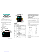
3. IA261/262 Panel Layout
The following figures show the panel layouts of the IA261 and IA262.
Top View
Reset Button
Power Input 1
Power Input 2
DI x 8
DO x 8
Front View
Rear View
LED Indicators
Serial, Tx/Rx
10/100 Mbps
Ethernet x 2
Powe r
Ready
P1
P2
RX TX
P
P
RX TX
LAN1
LAN2
CF
P4
RS-232/422/485
P3
RS-2
32/422/485
P1
RS-232/422/485
P2
RS-232/422/485
3
4
CompactFlash
Socket
Power, Ready,
Storage
LED Indicators
Serial, Tx/Rx
LED Indicators
CANBus, Tx/Rx
(IA262)
VGA Output
RS-232/422/485
Serial Port x 2
RS-232/422/485
Serial Port x 2
CANBus Port x 2
(IA262)
USB 2.0 Host x 2
DIN-Rail Kit
LED Indicators
The IA261/262 have 15 LED indicators on the front panel. Refer to the
following table for information about each LED.
LED Name LED Color LED Function
Power
Green Power is on
Ready
Green OS is ready and functioning normally
Storage
Green
Data is being written to or read from the
storage unit.
Orange 10 Mbps Ethernet connection
LAN 1/2
Green 100 Mbps Ethernet connection
Orange
Serial/CAN port is transmitting TX data
to the serial device.
P1-P4 (Tx)
Off Serial/CAN port is not transmitting TX
data to the serial device.
Orange Serial/CAN port is receiving RX data
from the serial device.
P1-P4 (Rx)
Off Serial/CAN port is not receiving RX data
to the serial device.
4. Installing the IA261/262
Wall or Cabinet Mounting
The IA261/262 comes with two metal brackets for attaching it to a wall
or the inside of a cabinet. Using two screws per bracket, first attach the
brackets to the rear of the IA261/262. Next, use two screws per bracket to
attach the IA261/262 to a wall or cabinet.
DIN-Rail Mounting
The aluminum DIN-Rail attachment plate is already attached to the
product casing. When attaching the plate to the IA261/262, make sure
that the stiff metal spring is at the top.
STEP 1: Insert the top of the
DIN-Rail into the slot just below the
stiff metal spring.
STEP 2: The DIN-Rail attachment
unit will snap into place as shown
below.
metal
spring
DIN-Rail
metal
spring
DIN-Rail
To remove the IA261/262 from the DIN-Rail, simply reverse Steps 1 and
2 above.
5. Connector Description
Power Connector
Connect the 12 to 48 VDC LPS or Class 2 power line to the IA261/262’s
terminal block or power jack. If the power is properly supplied, the
Power LED will light up. The OS is ready when the Ready LED glows a
solid green.
Grounding the IA261/262
Grounding and wire routing help limit the effects of noise due to
electromagnetic interference (EMI). Run the ground connection from the
ground screw to the grounding surface prior to connecting the power.
ATTENTION
This product is intended to be mounted to a well-grounded mounting
surface, such as a metal panel.
SG
SG: The Shielded Ground (sometimes called Protected
Ground) contact is the bottom contact of the 3-pin
power terminal block connector when viewed from
the angle shown here. Connect the SG wire to an
appropriate grounded metal surface.
P/N: 1802002600031

— 4 — —5— — 6—
VGA Connector
IA261/262 comes with a D-Sub 15-pin female connector to connect a
VGA CRT monitor.
Ethernet Ports
The two 10/100 Mbps Ethernet ports (LAN 1 and LAN 2) use RJ45
connectors.
Pin Signal
1 ETx+
2 ETx-
3 ERx+
6 ERx-
18
Serial Ports
The serial ports of the IA261 (P1 to P4) and the IA262 (P1 to P2) use
DB9 male connectors. Each port can be configured by software for
RS-232, RS-422, or RS-485. The pin assignments for the ports are shown
in the following table:
Pin RS-232 RS-422
RS-485
(4-wire)
RS-485
(2-wire)
1 DCD TxDA(-) TxDA(-) ---
2 RxD TxDB(+) TxDB(+) ---
3 TxD RxDB(+) RxDB(+) DataB(+)
4 DTR RxDA(-) RxDA(-) DataA(-)
5 GND GND GND GND
6 DSR --- --- ---
7 RTS --- --- ---
8 CTS --- --- ---
12345
6789
CAN Ports
The IA262 has 2 CAN ports for connecting CAN devices The CAN ports
of the IA262 (P3 to P4) use DB9 male connectors. The precise pin
assignments are shown in the following table:
Pin CAN
1 ---
2 CAN-L
3 ---
4 ---
5 ---
6 ---
7 CAN-H
8 ---
12345
6789
DI, DO
The IA261/262 have an 8-ch digital input and 8-ch digital output, both of
which support 3 KV optical isolation protection. The pinouts for the I/O
are shown in the following figures.
Digital Input Channel
(10-pin Terminal Block)
Digital Output Channel
(9-pin Terminal Block)
CompactFlash Socket
IA261/262 come with a CompactFlash socket for storage expansion, but
CompactFlash hot swap and PnP are not supported. This means that you
much disconnect the power source before inserting or removing the
CompactFlash card.
Console Port
The IA261/262’s console port is a 4-pin pin-header RS-232 port. It is
designed for serial console terminals, which are useful for identifying the
boot up message, or for debugging when the system cannot be booted up.
Reset Button
The IA261/262 has one reset button located on the top panel of the case.
The button can be used to switching the power off and then back on again.
The reset button also supports “Reset to default,” which is used to reload
the IA261/262’s factory-default configuration.
USB
The IA261/262 has 2 USB 2.0 full speed hosts (OHCI) that use a type A
connector. The ports support keyboard and mouse, and can also be used
to connect a FlashDisk for storing large amounts of data.
Real Time Clock
The IA261/262’s real time clock is powered by a lithium battery. We
strongly recommend that you do not replace the lithium battery without
help from a qualified Moxa support engineer. If you need to change the
battery, contact the Moxa RMA service team.
ATTENTION
There is a risk of explosion if the battery is replaced by an incorrect type
of battery.
6. Powering on the IA261/262
To power on the IA261/262, connect power to terminal block or power
jack (located on the top panel). Note that the Shielded Ground wire
should be connected to the right most pin of the terminal block. It takes
about 30 seconds for the system to boot up. Once the system is ready, the
Ready LED will light up.
The IA261/262 computer comes with two network interfaces. The default
IP addresses and netmasks of the network interfaces are as follows:
Default IP Address Netmask
LAN 1
192.168.3.127 255.255.255.0
LAN 2
192.168.4.127 255.255.255.0
7. Configuring the Ethernet Interface
WinCE 6.0 users should follow these steps:
Step 1: Go to [Start] Æ [Settings] Æ [Network and Dial-Up
Connections]. You will see two network interfaces.
Step 2: Right-Click the LAN interface to be configured and click
[property]. A configuration window will pop-up.
Step 3: Click OK after inputting the proper IP address and netmask.
Linux users should follow these steps:
If you use the console cable for first-time configuration of the Network
settings, use the following commands to edit the interfaces file:
Step 1:
#ifdown –a
//Disable LAN1/LAN2 interface first, before you reconfigure the LAN
settings. LAN 1 = eth0, LAN 2= eth1//
#vi /etc/network/interfaces
//check the LAN interface first//
Step 2:
After the boot setting of the LAN interface has been modified, use the
following command to activate the LAN settings immediately:
#sync; ifup –a
Click here for online support:
www.moxa.com/support
The Americas: +1-714-528-6777 (toll-free: 1-888-669-2872)
Europe: +49-89-3 70 03 99-0
Asia-Pacific: +886-2-8919-1230
China: +86-21-5258-9955 (toll-free: 800-820-5036)
© 2009 Moxa Inc. All rights reserved.
Reproduction without permission is prohibited.
/