Page is loading ...

Video Monitor
WV-BM140
Before attempting to connect or operate this product, please read these instructions completely
FRANÇAIS
DEUTSCH
ENGLISH
ESPAÑOL

The serial number of this product may be found on the
rear of the unit.
You should note the serial number of this unit in the
space provided and retain this book as a permanent
record of your purchase to aid identification in the event
of theft.
Model No.
Serial No.
THIS APPARATUS MUST BE EARTHED.
To ensure safe operation the three-pin plug supplied must be insert-
ed only into a standard three-pin power point which is effectively
earthed through the normal household wiring. Extension cords used
with the equipment must be three-core and be correctly wired to pro-
vide connection to earth. Wrongly wired extension cords are a major
cause of fatalities.
The fact that the equipment operates satisfactorily does not imply
that the power point is earthed and that the installation is completely
safe. For your safety, if in any doubt about the effective earthing of
the power point, consult a qualified electrician.
The lightning flash with arrowhead sym-
bol, within an equilateral triangle, is
interned to alert the user to the presence
of uninsulated "dangerous voltage" within
the product's enclosure that may be of
sufficient magnitude to constitute a risk of
electric shock to persons.
The exclamation point within an equilat-
eral triangle is intended to alert the user
to the presence of important operating
and maintenance (servicing) instructions
in the literature accompanying the appli-
ance.
WARNING:
TO PREVENT FIRE OR ELECTRIC SHOCK HAZARD, DO NOT EXPOSE THIS APPLIANCE TO RAIN OR MOIS
TURE.
CAUTION:
TO REDUCE THE RISK OF ELECTRIC SHOCK,
DO NOT REMOVE COVER (OR BACK), NO USER
SERVICEABLE PARTS INSIDE.
REFER SERVICING TO QUALIFIED SERVICE
PERSONNEL.
CAUTION
RISK OF ELECTRIC SHOCK
DO NOT OPEN
For Australia
FOR YOUR SAFETY PLEASE READ THE FOLLOWING TEXT CARE-
FULLY.
This appliance is supplied with a moulded three pin mains plug for your
safety and convenience.
A 13 amp fuse is fitted in this plug.
Should the fuse need to be replaced please ensure that the replacement
fuse has a rating of 13 amp and that it is approved by ASTA or BSI to
BS1362.
Check for the ASTA mark
H or the BSI mark G on the body of the
fuse.
If the plug contains a removable fuse cover you must ensure that it is
refitted when the fuse is replaced.
If you lose the fuse cover the plug must not be used until a replacement
cover is obtained.
A replacement fuse cover can be purchased from your local Panasonic
Dealer.
IF THE FITTED MOULDED PLUG IS UNSUITABLE FOR THE SOCK-
ET OUTLET IN YOUR HOME THEN THE FUSE SHOULD BE
REMOVED AND THE PLUG CUT OFF AND DISPOSED OF SAFELY.
THERE IS A DANGER OF SEVERE ELECTRICAL SHOCK IF THE
CUT OFF PLUG IS INSERTED INTO ANY 13 AMP SOCKET.
If a new plug is to be fitted please observe the wiring code as shown
below.
If in any doubt please consult a qualified electrician.
WARNING: This apparatus must be earthed.
IMPORTANT
The wires in this mains lead are coloured in accordance with the follow-
ing code.
Green-and-yellow: Earth
Blue: Neutral
Brown: Live
As the colours of the wire in the mains lead of this appliance may not
correspond with the coloured markings identifying the terminals in your
plug, proceed as follows.
The wire which is coloured green-and-yellow must be connected to
the terminal in the plug which is marked with the letter E or by the earth
symbol
I or coloured green or green-and-yellow.
The wire which is coloured blue must be connected to the terminal in
the plug which is marked with the letter N or coloured black.
The wire which is coloured brown must be connected to the terminal
in the plug which is marked with the letter L or coloured red.
How to replace the fuse
Open the fuse compartment with
a screwdriver and replace the fuse
and fuse cover.
For U.K.
ENGLISH VERSION
Wij verklaren als enige aansprakelijke, dat het product waarop deze
verklaring betrekking heeft, voldoet aan de volgende normen of
andere normatiefve dokumenten, overeenkomstig de bepalingen
van Richtlijnen 73/23/EEC en 89/336/EEC.
Vi erklærer os eneansvarlige for, at dette produkt, som denne
deklaration omhandler, er i overensstemmelse med den følgende
standarder eller andre normative dokumenter i følge bestem-
melserne i direktivene 73/23/EEC og 89/336/EEC.
Vi deklarerar härmed värt fulla ansvar för att den produkt till vilken
denna deklaration hänvisar är i överensstämmelse med standard-
dokument, eller andra normativa dokument som framstölls i Direktiv
73/23/EEC och 89/336/EEC.
Ilmoitamme yksinomaisella vastuullamme, että tuote, jota tämä
ilmoitus koskee, noudattaa seuraavia standardeja tai muita ohjeel-
lisia asiakirjoja, jotka noudattavat direktiivien 73/23/EEC ia
89/336/EEC. säädöksiä.
Vi erklærer oss alene ansvarlige for at produktet som denne
erklæringen gjelder for, er i overensstemmelse med følgende
normer eller andre normgivende dokumenter som fælger bestem-
melsene i direktiven 73/23/EEC og 89/336/EEC.
We declare under our sole responsibility that the product to which
this declaration relates is in conformity with the standards or other
normative documents following the provisions of Directives
EEC/73/23 and EEC/89/336.
Nosotros declaramos bajo nuestra ùnica responsabilidad que el
producto a que hace referencia esta declaraciòn està conforme con
las normas u otros documentos normativos siguiendo las estipula-
ciones de la directivas CEE/73/23 y CEE/89/336.
FUSE

CONTENTS
PREFACE ............................................................................................................................................................................................ 2
FEATURES .......................................................................................................................................................................................... 2
PRECAUTIONS ................................................................................................................................................................................... 2
MAJOR OPERATING CONTROLS AND THEIR FUNCTIONS ............................................................................................................ 3
SETUP OPERATION ........................................................................................................................................................................... 6
OPERATING PROCEDURES .............................................................................................................................................................. 9
CONNECTIONS .................................................................................................................................................................................. 11
SYSTEM CONNECTION ..................................................................................................................................................................... 15
SPECIFICATIONS ............................................................................................................................................................................... 16
OPTIONAL ACCESSORIES ................................................................................................................................................................ 16
-1-
ENGLISH

-2-
FEATURES
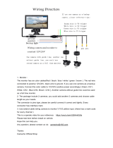
• Up to four specified cameras can be connected to this
monitor with an alarm feature. This number can be
increased to 7 specified cameras by using the camera
extension unit WV-AD110A.
• The monitor has a 14” diagonal screen (13” diagonal
actual visual size).
• The sequential switching interval is selectable between
1, 2, 3, 4, 5, 6, 7, 8, 9, 10, 15, 20, 25, or 30 seconds.
• Stand-by (STD BY) mode is available for sequential
switching without a picture on the monitor.
• Alarm period is selectable between 1, 5, 10, 20, 30, 40,
50, or 60 seconds.
• Alarm control output is supplied for a buzzer or chime.
• Automatic Reset Function is linked to spot monitor con-
trol input. An automatic reset time can be set to 1-60
seconds.
• A CCVE camera with microphone can be connected to
this monitor.
PRECAUTIONS
• Do not block the ventilation slots. Place the monitor at
least 5 cm (2 inches) apart from the wall.
• Do not expose the monitor to water or moisture.
Do not operate the monitor if it becomes wet. Turn the
power off immediately and ask a qualified service per-
son for servicing. Moisture can damage the monitor
and also create the danger of electric shock.
• Do not attempt to disassemble the monitor. To prevent
electric shock, do not remove screws or covers. There
are no user-serviceable parts inside. Ask a qualified
service person for serving.
• Use the monitor under conditions where temperature is
from −10°C - + 50°C (14°F - 122°F), and humidity is
below 90%.
The input power resource is 220 - 240V AC, 50 Hz.
Do not operate the monitor under extreme ambient
conditions beyond the specified temperature, humidity,
or power resource ratings.
PREFACE
The Panasonic's WV-BM140 is a desk-top closed circuit
Video Monitor especially designed for surveillance.
Up to four specified cameras can be connected to this
monitor for surveillance by sequential or manual switching
between cameras. Monitor and cameras form a simple sys-
tem, interconnected by coaxial cables that carry DC power
and vertical drive pulse to the cameras. The system can be
expanded to a CCVE system by adding an intercom and
sensors.
• Automatic bypass circuit works to skip channels to
which no camera is connected.
• The following functions are available from the setup
menu:
• Camera Identification Display (CAMERA ID)
• Audio Selection (AUDIO SELECT)
• Timing Selection (TIMING SELECT)
• Sequential Time Adjustment (SEQ TIME ADJ)
• Alarm Buzzer Setting (ALARM BUZZER)
• Alarm Time Adjustment (ALARM TIME ADJ)
• Automatic Resetting (AUTO RESET)
• Manual Skipping (MANUAL SKIP)
• This model is not designed for rack mounting.
• Do not stack two or more sets. If more than two moni-
tors are used, place them at least 15 cm (6 inches)
apart. Otherwise the monitor may produce noise in the
display.
• Do not use the monitor in a car or other places where it
may be exposed to severe vibration.

ON
ON
OFF
STD BY
POWER
DISPLAY
MODE
INPUT
SELECT
CAMERA
VTR
AUDIO
H.HOLD
V.HOLD
HEIGHT
BRIGHT
V.LIN
CONTRAST
SEQUENCE
SET UP
1
Video Monitor WV-BM
140
2 3 4
-3-
MAJOR OPERATING CONTROLS AND THEIR FUNCTIONS
■ FRONT VIEW
8. Height Control (HEIGHT)
Turn this control clockwise to extend the picture verti-
cally. Turn it counterclockwise to shrink the picture ver-
tically.
1. Power Switch (POWER)
This switch turns the power of the monitor on or off.
Press this switch once (;) to turn the monitor on.
Press it again (l) to turn the monitor off.
2. Power Indicator
This indicator lights up to indicate that the power is on.
3. DISPLAY MODE Switch (STD BY ;/ON l)
ON: The camera picture will appear on the monitor.
STD BY: The camera picture will not appear on the
monitor in the sequence mode, but is supplied to
the REC OUT connector.
4. INPUT SELECT Switch (VTR ;/CAMERA l)
VTR: The VTR playback picture or video that is con-
nected to the PLAY IN connector can be
observed.
CAMERA: The picture of the camera that is connected
to the CAMERA INPUT connector can be
observed.
5. Audio Control (AUDIO)
Turn this control clockwise to increase the audio level.
Turn it counterclockwise to decrease the audio level.
6. Horizontal Hold Control (H. HOLD)
This control is used to adjust the horizontal position of
the picture.
7. Vertical Hold Control (V. HOLD)
This control is used to adjust the vertical position of the
picture.

-4-
2
12341234
GND GNDSTDBY
ALARM CONTROL
OUT
ALL
MODE
RESETRECOVER
SPOT MONITOR CONTROL IN REMOTE OUT
1
CAMERA INPUT
CAMERA
VTR
43
REC
OUT
AUDIO
IN
AUDIO
OUT
CAMERA
EXTENSION IN
PLAY
IN
OUT IN
TIMING
SELECT
CAUTION
RISK OF ELECTRIC SHOCK, DO NOT OPEN
ATTENTION
RISQUE DE CHOCS ELECTRIQUES
NE PAS OUVRIR
■ REAR VIEW
9. Bright Control (BRIGHT)
Turn this control clockwise to increase the picture
brightness. Turn it counterclockwise to decrease the
picture brightness.
10. Vertical Linearity Control (V.LIN)
This control is used to correct vertical nonlinearities in
the picture.
11. Contrast Control (CONTRAST)
Turn this control clockwise to increase the contrast of
the picture.
Turn it counterclockwise to decrease the contrast of
the picture.
12. Sequence / Setup Switch
(SEQUENCE / SET UP)
This switch is used to display a series of camera pic-
tures on the monitor. Each time this switch is pressed
switches to the next camera picture.
If you press and hold down this switch for 2 seconds or
longer with the INPUT SELECT switch in CAMERA
position, the SET UP MENU appears on the monitor.
13. Camera Selection Switch (1)/ Up Switch (
D)
14. Camera Selection Switch (2) / Down Switch (C)
15. Camera Selection Switch (3) / Left Switch (A)
16. Camera Selection Switch (4) / Right Switch (B)
17. External Control Connection Terminals
RECOVER
This terminal is used to reset the spot camera pic-
ture and return to the sequential operation by
receiving the recover signal from the time lapse
VTR.
SPOT MONITOR CONTROL IN (1-4)
These terminals are used to receive the alarm con-
trol signal from the intercom or alarm sensor.
Note: The short-circuit voltage across these terminals
should be 0 - 0.2 volt when the intercom or alarm
sensor is activated.
ALARM CONTROL OUT
These terminals are used to supply the alarm con-
trol signal to external equipment such as the Time
Lapse VTR or buzzer. When an intercom or alarm
sensor is connected to the spot monitor control
terminal, the alarm output signal is supplied from
the STD BY or ALL MODE terminal to the time
lapse VTR or buzzer.

-5-
STD BY-GND Connection
The alarm output signal is supplied only when the
DISPLAY MODE switch is set to STD BY.
ALL MODE-GND Connection
The alarm output signal is supplied regardless of
the display mode.
REMOTE OUT
These terminals supply the remote control output
signal or recover output signal when the camera is
selected manually or automatically, or by using
external control.
18. Timing Select Output Connector
(TIMING SELECT, OUT)
This connector supplies the timing pulse signals for
switching in the sequence operation of other extensible
systems, such as another CCVE system or sequential
switcher. This connector sends the signal that is sup-
plied to the TIMING SELECT IN connector.
19. Timing Select Input Connector
(TIMING SELECT, IN)
This connector receives the external timing pulse for
the sequential operation from the time lapse VTR or
another CCVE system.
20. Audio Output Connector (AUDIO OUT)
This connector supplies the audio recorded with the
picture to the time lapse VTR, if the specified camera
with microphone is connected to the CAMERA INPUT
connector.
21. Audio Input Connector (AUDIO IN)
This connector receives the audio signal from an exter-
nal source.
While the INPUT SELECT switch is set to VTR, the
audio from the external source that is connected to this
connector can be monitored through the internal
speaker.
22. Power Cord
Caution: 220 - 240V AC supply only.
23. Playback Input Connector (PLAY IN)
This connector receives the video signal from an exter-
nal source such as a VTR for monitoring.
While the INPUT SELECT switch is set to VTR, the
video from the external source that is connected to this
connector is displayed on the monitor.
24. Record Output Connector (REC OUT)
This connector supplies the video signal of the cam-
eras to an additional monitor or VTR.
The video signal of the camera is supplied to this con-
nector even if the DISPLAY MODE switch is set to STD
BY.
25. Camera Input Connectors (CAMERA INPUT, 1/2/3/4)
Connect the specified cameras to these connectors.
These connectors supply DC power and vertical drive
pulse to the cameras and receive the video and audio
signal from the cameras.
Notes:
• Be sure to connect only the specified camera.
• Connect cameras after making sure that the power
of the monitor is off.
Connecting the camera with the power of the monitor
turned on will activate the connection error protection
circuit, so the camera will not work.
26. Camera Extension Input Connector
(CAMERA EXTENSION IN)
This is a 12-pin connector for the Camera Extension
unit used to connect 3 additional cameras.
The pin assignment is are shown below.
Pin 1 : Logic Signal for Sequential Control
Pin 2 : Logic Signal for Sequential Control
Pin 3 : Logic Signal for Sequential Control
Pin 4 : Video Input Signal
Pin 5 : Ground
Pin 6 : Logic Signal for Sequential Control
Pin 7 : Logic Signal for Sequential Control
Pin 8 : Logic Signal for Sequential Control
Pin 9 : Logic Signal for Sequential Control
Pin 10 : Logic Signal for Sequential Control
Pin 11 : Vertical Drive Output Signal
Pin 12 : Not used

SEQUENCE
1 2 3 4
SET UP
-6-
SET UP OPERATION
Make sure that the connections of peripherals and those
made at the alarm output terminals are correct and firm.
The SET UP MENU is not displayed unless a camera is
connected. (Refer to “CONNECTIONS” on page 11.)
The SET UP MENU is described in detail in the following
section “Setting Procedure”.
Set the DISPLAY MODE switch to ON to display the SET UP
MENU.
Set the INPUT SELECT switch to CAMERA to display the
SET UP MENU. If set to VTR, the SET UP MENU is not dis-
played.
When you want to display the SET UP MENU, make sure
the followings:
• The position of the DISPLAY MODE switch is ON.
• The position of the INPUT SELECT switch is CAMERA.
Setup operations are performed by the following switches
on the front panel.
Up Switch : The cursor moves upwards.
Down Switch : The cursor moves downwards.
Right Switch : The cursor moves to the right. This switch
selects the mode and can be used to
adjust some levels.
Left Switch : The cursor moves to the left. This switch
selects the mode and can be used to
adjust some levels.
Setup Switch : The menu is selected by this switch and
determine the selection.
Right Switch
Left Switch
Setup Switch
Down Switch
Up Switch
• Editing the Set Up menu
To edit the SET UP MENU (change settings), use the
Up/Down switches (D/C) and Right/Left switches
(B/A) to move the cursor to SET UP DISABLE in the
bottom line. Press the SET UP switch. “SET UP
ENABLE” will be displayed.
Move the cursor to the item(s) you want to change until
you reach END.
Important Notices:
• When “SET UP DISABLE” is displayed in the bot-
tom line of the SET UP MENU, you can not enter
actual mode setting. This is to prevent setting of
the wrong mode.
• When the cursor is moved to END and the SET UP
MENU closed after changing settings (ex. ON-
OFF), the new values are stored in the (Electric
Erasable) memory and Programmable Read Only
Memory (EEPROM). These values remain valid
until new values are stored, even if the power of
the monitor is off.
• All Reset Operation
All Reset allows you to reset all setup menu items to
the factory settings if you are unsure about the correct
settings. Proceed as follows:
(1) Make sure that the DISPLAY MODE switch is set to
ON and the INPUT SELECT switch to CAMERA,
and that the SET UP MENU is not displayed.
(2) Turn off the power of the monitor.
(3) Turn on the power of the monitor while pressing
the SET UP switch and the Right switch (B) simul-
taneously.
All adjustments and selections are reset to the fac-
tory settings.
** SET UP MENU **
CAMERA ID 1 2 3 4
1 CAMERA
AUDIO SELECT SEQ
TIMING SELECT INT
SEQ TIME ADJ 1 SEC
ALARM BUZZER ON
ALARM TIME ADJ 60 SEC
AUTO RESET ON
MANUAL SKIP 1 2 3 4
END SET UP DISABLE
Press and hold down the SET UP switch for 2 seconds
or more.
The SET UP MENU is displayed on the monitor as
shown above.
By observing this menu, you can check the present
settings. Check the current settings on the menu.
Refer to the sections below for a detailed description of
menu items. If you decide not to make any changes
after checking the current settings, move the cursor to
END at the start of the bottom line, and press the SET
UP switch to return to normal camera picture mode.
Blinking
• Opening the Setup Menu

-7-
1-1. Move the cursor to CAMERA ID and select the desired
camera by using the Left (A) or Right (B) switch.
To display the camera identification, press the SET UP
switch repeatedly.
1-2. After completing step 1-1, move the cursor to the sec-
ond line by using the Down (C) switch.
Press the SET UP switch and set the camera identifica-
tion as in 1-3 below.
1-3. Select the camera identification from the characters
shown below.
** SET UP MENU **
CAMERA ID 1 2 3 4
1 CAMERA
AUDIO SELECT SEQ
TIMING SELECT INT
SEQ TIME ADJ 1 SEC
ALARM BUZZER ON
ALARM TIME ADJ 60 SEC
AUTO RESET ON
MANUAL SKIP 1 2 3 4
END SET UP ENABLE
2-1. Move the cursor to AUDIO SELECT.
Select Sequential (SEQ) or Fixed (1, 2, 3 or 4) by using
the Left (A) or Right (B) switch.
2-2. When set to “SEQ”, the audio signal is switched with
the channel.
2-3. When set to “1, 2, 3, 4”, the audio signal is fixed to the
selected channel.
** SET UP MENU **
CAMERA ID 1 2 3 4
1 CAMERA
AUDIO SELECT SEQ
TIMING SELECT INT
SEQ TIME ADJ 1 SEC
ALARM BUZZER ON
ALARM TIME ADJ 60 SEC
AUTO RESET ON
MANUAL SKIP 1 2 3 4
END SET UP ENABLE
** SET UP MENU **
CAMERA ID 1 2 3 4
1 CAMERA
AUDIO SELECT SEQ
TIMING SELECT INT
SEQ TIME ADJ 1 SEC
ALARM BUZZER ON
ALARM TIME ADJ 60 SEC
AUTO RESET ON
MANUAL SKIP 1 2 3 4
END SET UP ENABLE
** SET UP MENU **
CAMERA ID 1 2 3 4
1 CAMERA
AUDIO SELECT SEQ
TIMING SELECT INT
SEQ TIME ADJ 1 SEC
ALARM BUZZER ON
ALARM TIME ADJ 60 SEC
AUTO RESET ON
MANUAL SKIP 1 2 3 4
END SET UP ENABLE
** SET UP MENU **
CAMERA ID 1 2 3 4
1 CAMERA
AUDIO SELECT SEQ
TIMING SELECT INT
SEQ TIME ADJ 1 SEC
ALARM BUZZER ON
ALARM TIME ADJ 60 SEC
AUTO RESET ON
MANUAL SKIP 1 2 3 4
END SET UP ENABLE
Setting Procedure
1. Camera Identification Setting
(CAMERA ID)
This item has two functions.
In the upper line, you can set whether to have the cam-
era ID displayed or not.
ON: The camera number (1, 2, 3 or 4) indicates that
the picture is displayed with the camera ID.
OFF: The “•” mark indicates that the picture is dis-
played without the camera ID.
The lower line is used to edit the camera ID.
Press the SET UP Switch.
Press the Down Switch (C).
After completing the selection,
press the SET UP Switch.
← (D)(C) →
0 1 2 3 4 5 6 7 8 9 : ; A B C D E F G H I J K L M N
O P Q R S T U V W X Y Z Ä Ü Ö Æ Ñ Å Ø " # ' ( )
∗ + , - . / ← = →
.
(space)
Use the Up/Down switches (D/C) to select characters.
To correct the character that is edited wrongly, press
the Left/Right switches (A/B) to select the character
to be corrected and press the Up/Down switches
(D/C) to select a new character.
1-4. To register the camera identification, move the cursor
back to CAMERA ID.
Note: The Camera Identification setting is not memo-
rized unless CAMERA ID is selected again.
2. Audio Selection (AUDIO SELECT)
This item is used to select the audio source.
1-4: You can monitor the audio from the channel you
selected by pressing the camera selection switch.
SEQ: You can monitor the audio that is switched with
the picture by sequential switching.

-8-
4. Sequential Time Adjustment
(SEQ TIME ADJ)
This item is used to select the switching timing when
you selected INT for TIMING SELECT.
You can select the sequential time from 1, 2, 3, 4, 5, 6,
7, 8, 9, 10, 15, 20, 25, or 30 seconds.
** SET UP MENU **
CAMERA ID 1 2 3 4
1 CAMERA
AUDIO SELECT SEQ
TIMING SELECT INT
SEQ TIME ADJ 1 SEC
ALARM BUZZER ON
ALARM TIME ADJ 60 SEC
AUTO RESET ON
MANUAL SKIP 1 2 3 4
END SET UP ENABLE
** SET UP MENU **
CAMERA ID 1 2 3 4
1 CAMERA
AUDIO SELECT SEQ
TIMING SELECT INT
SEQ TIME ADJ 1 SEC
ALARM BUZZER ON
ALARM TIME ADJ 60 SEC
AUTO RESET ON
MANUAL SKIP 1 2 3 4
END SET UP ENABLE
4-1. Move the cursor to SEQ TIME ADJ.
4-2. Select sequential time by using the Left (A) or Right
(B) switch.
Sequential time can be selected from (approx.) 1, 2, 3,
4, 5, 6, 7, 8, 9, 10, 15, 20, 25 or 30 seconds.
5. Alarm Buzzer On/Off (ALARM BUZZER)
This item is used to turn the alarm buzzer function on
or off.
** SET UP MENU **
CAMERA ID 1 2 3 4
1 CAMERA
AUDIO SELECT SEQ
TIMING SELECT INT
SEQ TIME ADJ 1 SEC
ALARM BUZZER ON
ALARM TIME ADJ 60 SEC
AUTO RESET ON
MANUAL SKIP 1 2 3 4
END SET UP ENABLE
6-1. Move the cursor to ALARM TIME ADJ.
6-2. Set the duration of the alarm buzzer by using the Left
(A) or Right (B) switch.
Alarm buzzer can be selected from (approx.) 1, 5, 10,
20, 30, 40, 50 or 60 seconds.
7. Auto Reset Setting (AUTO RESET)
This item is used to turn the automatic resetting func-
tion on or off.
** SET UP MENU **
CAMERA ID 1 2 3 4
1 CAMERA
AUDIO SELECT SEQ
TIMING SELECT INT
SEQ TIME ADJ 1 SEC
ALARM BUZZER ON
ALARM TIME ADJ 60 SEC
AUTO RESET ON
MANUAL SKIP 1 2 3 4
END SET UP ENABLE
7-1. Move the cursor to AUTO RESET.
7-2. Turn the automatic resetting function on or off by using
the Left (A) or Right (B) switch.
When ON is selected for AUTO RESET, the alarm
mode will be reset automatically 60 seconds after the
sensor signal is received.
** SET UP MENU **
CAMERA ID 1 2 3 4
1 CAMERA
AUDIO SELECT SEQ
TIMING SELECT INT
SEQ TIME ADJ 1 SEC
ALARM BUZZER ON
ALARM TIME ADJ 60 SEC
AUTO RESET ON
MANUAL SKIP 1 2 3 4
END SET UP ENABLE
3-1. Move the cursor to TIMING SELECT.
3-2. Select Internal Timing (INT) or External Timing (EXT) by
using the Left (A) or Right (B) switch.
Note: Set this item to EXT when the timing signal is
input from another video monitor or time lapse
VTR.
3. Timing Selection (TIMING SELECT)
This item is used to select the switching timing.
INT: The switching timing is determined by the setting
of SEQ TIME ADJ.
EXT: The switching timing is determined by another
CCVE system or the time lapse VTR.
5-1 Move the cursor to ALARM BUZZER.
5-2. ALARM BUZZER On/Off can be selected by using the
Left (A) or Right (B) switch.
The alarm sounds for 1-60 seconds (selected by
ALARM TIME ADJ) when an alarm signal is received.
6. Alarm Time Adjustment
(ALARM TIME ADJ)
This item is used to select the duration of the alarm
buzzer sound.
You can select the duration of the alarm buzzer sound.

-9-
** SET UP MENU **
CAMERA ID 1 2 3 4
1 CAMERA
AUDIO SELECT SEQ
TIMING SELECT INT
SEQ TIME ADJ 1 SEC
ALARM BUZZER ON
ALARM TIME ADJ 60 SEC
AUTO RESET ON
MANUAL SKIP 1 . . 4
END SET UP ENABLE
8. Manual Skip Setting
(MANUAL SKIP)
This item is used to skip the picture of a specified cam-
era for monitoring in sequential switching.
8-1. Move the cursor to MANUAL SKIP.
8-2. Select the camera number that you want to skip by
using the Right (A) or Left (B) switch. This setting
works only for the channels that are connected with
cameras.
8-3. Press the SET UP switch. The “•” mark appears. The
selected camera picture is skipped.
Note: To cancel to skip the camera picture, select the
“•” mark and press the SET UP switch again. The
camera number appears.
OPERATING PROCEDURES
ON
ON
OFF
STD BY
POWER
DISPLAY
MODE
INPUT
SELECT
CAMERA
VTR
AUDIO
H.HOLD
V.HOLD
HEIGHT
BRIGHT
V.LIN
CONTRAST
SEQUENCE
SET UP
1
Video Monitor WV-BM
140
2 3 4
1
2
1. Press the POWER switch once to turn the power ON.
2. Set the DISPLAY MODE switch to ON.
3. Press the SEQUENCE / SET UP switch for 2 seconds
or longer.
4. Set the desired sequential time from the SET UP menu.
ON
ON
OFF
STD BY
POWER
DISPLAY
MODE
INPUT
SELECT
CAMERA
VTR
AUDIO
H.HOLD
V.HOLD
HEIGHT
BRIGHT
V.LIN
CONTRAST
SEQUENCE
SET UP
1
Video Monitor WV-BM
140
2 3 4
ON
ON
OFF
STD BY
POWER
DISPLAY
MODE
INPUT
SELECT
CAMERA
VTR
AUDIO
H.HOLD
V.HOLD
HEIGHT
BRIGHT
V.LIN
CONTRAST
SEQUENCE
SET UP
1
Video Monitor WV-BM
140
2 3 4
1
2
3
Selection of Camera
1. Press the POWER switch on the front panel once to
turn the power ON.
2. Press the desired camera selection switch.
Notes :
1. It takes a few seconds after turning on the power
of the monitor until a normal picture is displayed.
2. When turned on, the monitor is automatically in
sequence mode.
3. The picture of the desired camera can be dis-
played on the monitor by pressing the corre-
sponding camera selection switch, even if the
monitor is in sequence mode.
4. The picture of the desired camera can be dis-
played on the monitor by pressing the corre-
sponding camera selection switch, even if the
monitor is in STD BY mode.
Caution :
When the power of the monitor is turned on and off
repeatedly in a short period of time, the camera may
not be turned on due to operation of the misconnection
protection circuit.
In this case, keep the POWER switch in the OFF posi-
tion for a few seconds before turning it on again.
Sequence Mode (more than two cameras)

-10-
ON
ON
OFF
STD BY
POWER
DISPLAY
MODE
INPUT
SELECT
CAMERA
VTR
AUDIO
H.HOLD
V.HOLD
HEIGHT
BRIGHT
V.LIN
CONTRAST
SEQUENCE
SET UP
1
Video Monitor WV-BM
140
2 3 4
ON
ON
OFF
STD BY
POWER
DISPLAY
MODE
INPUT
SELECT
CAMERA
VTR
AUDIO
H.HOLD
V.HOLD
HEIGHT
BRIGHT
V.LIN
CONTRAST
SEQUENCE
SET UP
1
Video Monitor WV-BM
140
2 3 4
ON
ON
OFF
STD BY
POWER
DISPLAY
MODE
INPUT
SELECT
CAMERA
VTR
AUDIO
H.HOLD
V.HOLD
HEIGHT
BRIGHT
V.LIN
CONTRAST
SEQUENCE
SET UP
1
Video Monitor WV-BM
140
2 3 4
1
2
3,7
6
5
1. Press the POWER switch once to turn the power ON.
2. Set the DISPLAY MODE switch to ON.
3. Press the SEQUENTIAL / SETUP switch for 2 seconds
or longer.
4. Set the sequential time from the SET UP MENU.
5. Set the DISPLAY MODE switch to STD BY.
The picture on the monitor disappears. However,
sequential switching is carried out and the picture can
be observed on an additional monitor connected to
the REC OUT connector of this monitor.
6. When you want to monitor a specific camera picture,
press the corresponding camera selection switch.
7. By pressing the SEQUENCE / SET UP switch again,
the picture on the monitor disappears and the mode
returns to sequential switching in STD BY.
Standby(STD BY) Mode Monitoring Picture
(Usually no picture displayed)
VTR Playback Mode
1. Press the POWER switch once (;) to turn on the mon-
itor and the cameras.
2. Set the DISPLAY MODE switch to ON.
3. Set the INPUT SELECT switch to VTR for observing the
playback picture.
Automatic Reset function for Spot Monitor
Mode
This monitor has a built-in automatic reset circuit. When
AUTO RESET on the SET UP MENU is set to ON, the spot
monitoring mode is automatically reset to the sequential
switching mode about 60 seconds after the spot monitor
input signal is received.
The operation of the automatic reset circuit is linked to the
spot monitor control input as follows :
1. Alarm Sensors
The camera is selected by a spot monitor control input
signal supplied from an alarm sensor. After about 60
seconds, the camera picture returns to sequential
switching mode.
2. Intercom
(a) On line
The camera is selected by a spot monitor control input
signal supplied from the intercom. The camera picture
is displayed as long as the intercom is on line. It
returns to sequential switching when the line is discon-
nected.
(b) Calling by the beeper/chime
The camera is selected by a spot monitor control input
signal supplied from the intercom. After about 60 sec-
onds, the camera picture returns to sequential switch-
ing mode.
3. Time Lapse VTR
The camera is selected by a spot monitor control input
signal supplied from the time lapse VTR. After about 60
seconds, the camera picture returns to the sequential
switching mode.
1
3
42
12
Note: Sequential switching features an automatic
bypass circuit that detects the presence of DC
power for a camera, thereby automatically skip-
ping an input connector that has no camera con-
nected.

-11-
CONNECTIONS
Precautions :
1. These connections should be made by qualified service personnel or system installers.
2. Keep the power switches of the monitor, optional camera, and optional camera extension unit in the OFF position during the
connection.
■ Connection with camera
• Connect single coaxial cables between the cameras
and monitor (CAMERA INPUT). The maximum coaxial
cable length is as follows;
Cautions
1. Keep the POWER switch of the monitor OFF during the
camera connection.
2. Connect the specified cameras (multiplexed VP).
If other types of cameras are connected, the connec-
tion error protection circuit will be activated, so the
CCVE system will not work.
This system allows to synchronize the timing pulse on the monitor side.
• SET UP MENU setting
Set TIMING SELECT to INT.
• Sequential Switcher setting
Set SEQ TIME ADJ to EXT.
■ Connection with Sequential Switcher
21
CAMERA INPUT
CAMERA
VTR
43
REC
OUT
AUDIO
IN
AUDIO
OUT
CAMERA
EXTENSION IN
PLAY
IN
Coaxial Maximum DC R/1 000 ft. of
Cable Type Cable Length Inner Conductor
RG-59/U 200 m (660 ft.) Less than 30 Ω
RG-6/U 500 m (1 650 ft.) Less than 12 Ω
2
12341234
GND GNDSTDBY
ALARM CONTROL
OUT
ALL
MODE
RESETRECOVER
SPOT MONITOR CONTROL IN REMOTE OUT
1
CAMERA INPUT
CAMERA
VTR
43
REC
OUT
AUDIO
IN
AUDIO
OUT
CAMERA
EXTENSION IN
PLAY
IN
OUT IN
TIMING
SELECT
TIMING SELECT OUT
Video Monitor WV-BM140
VIDEO INPUT
Sync Timing Cable (option)
Sequential Switcher
Timing Input Connector
Other Monitor
Video Monitor WV-BM140
CAMERA INPUT
BNC Connector
Camera
Coaxial Cable
(terminated at 75 Ω)
The maximum DC resistance of the coaxial cable
between the cameras and video monitor is 20 Ω.

-12-
■ Basic System with Optional Camera
Extension Unit
• Connect single coaxial cables between the cameras
and monitor/camera extension unit (CAMERA INPUT).
• Connect the camera extension cable from the camera
extension unit at the CAMERA EXTENSION IN connec-
tor on the monitor.
• Up to 2 Camera Extension Units can be connected.
Notes:
• Set TIMING SELECT in the SET UP MENU to INT for
the master monitor and to EXT for the slave monitor.
• When no cameras are connected, the monitor picture
is unstable. This is normal and not a malfunction.
21
CAMERA INPUT
CAMERA
VTR
43
REC
OUT
AUDIO
IN
AUDIO
OUT
CAMERA
EXTENSION IN
PLAY
IN
Camera Extension Unit
WV-AD110A
Video Monitor WV-BM140
Coaxial Cable
Additional Cameras
Coaxial Cable
Camera Extension Unit
WV-AD110A
■ Additional Basic System
• Connect the coaxial cables between the cameras and
monitor.
• Connect the Sync Timing Cable between the monitors.
2
12341234
GND GNDSTDBY
ALARM CONTROL
OUT
ALL
MODE
RESETRECOVER
SPOT MONITOR CONTROL IN REMOTE OUT
1
CAMERA INPUT
CAMERA
VTR
43
REC
OUT
AUDIO
IN
AUDIO
OUT
CAMERA
EXTENSION IN
PLAY
IN
OUT IN
TIMING
SELECT
2
12341234
GND GNDSTDBY
ALARM CONTROL
OUT
ALL
MODE
RESETRECOVER
SPOT MONITOR CONTROL IN REMOTE OUT
1
CAMERA INPUT
CAMERA
VTR
43
REC
OUT
AUDIO
IN
AUDIO
OUT
CAMERA
EXTENSION IN
PLAY
IN
OUT IN
TIMING
SELECT
Video Monitor WV-BM140
Video
Monitor
WV-BM140
Coaxial Cable
Coaxial Cable
TIMING SELECT: INT
TIMING SELECT: EXT

-13-
■ Connection with the VTR
TL
21
CAMERA INPUT
CAMERA
VTR
43
REC
OUT
AUDIO
IN
AUDIO
OUT
CAMERA
EXTENSION IN
PLAY
IN
Video Monitor WV-BM140
Time Lapse
VTR
VIDEO
OUTPUT
Coaxial Cable
BNC Connector
■ Connection with the Intercom and Alarm Sensors
Connect a coaxial cable between the video output connec-
tor of the VTR and the PLAY IN of this monitor.
Power source level
Calling period or activated
period (less than 0.2V)
Less than 12V DC
0V
Intercom
Master Unit
DC Voltmeter
There are limits on the wiring length in connecting an inter-
com system, alarm sensor system, optional units, and video
monitor.
12341234
GND GNDSTDBY
ALARM CONTROL
OUT
ALL
MODE
RESETRECOVER
SPOT MONITOR CONTROL IN REMOTE OUT
Intercom
Mater Unit
• Use two-wire connections for the intercom system and
alarm sensors/switches.
• The power source for the intercom system and alarm
sensors/switches should be less than DC 12V.
• The line voltage for the activated intercom or alarm
sensor/switch should be 0 - 0.2V DC.
For example, the maximum wiring length for a intercom sys-
tem are as follows ;
Wires Equivalent Maximum
(mm/Q'ty) AWG SWG Wiring length
0.18/12 22 23 150m
0.18/20 20 21 250m
0.18/30 18 19 400m
0.18/50 16 17 600m
AWG: American Wire Gauge
SWG: British Legal Standard Wire Gauge
The polarity of the intercom system and the Spot Monitor
Control In terminals of the monitor should be matched.
Check the polarity of the intercom system with a tester
(meter).
GND
(+)
143
TL
Video Monitor
WV-BM140
Time Lapse VTR
Other Monitor
REC
OUT
VIDEO
OUTPUT
PLAY
IN
VIDEO
INPUT
Noise
Note: Avoid the following connection if you want to monitor
the playback picture of a VTR.

-14-
The polarities for the alarm and Alarm Control Output of the
monitor should be matched.
The power capacity of the alarm should be DC24V, max.
100mA.
If the power capacity of the alarm is less than 100mA, DC
24V, the alarm can be connected directly to the Alarm
Control Out terminal.
If the power capacity of the alarm is more than 100mA,
DC24V, the alarm cannot be connected to the terminal
directly. In this case, a relay circuit should be used for the
alarm.
NC NO
C
12341234
GND GNDSTDBY
ALARM CONTROL
OUT
ALL
MODE
RESETRECOVER
SPOT MONITOR CONTROL IN REMOTE OUT
24V Relay
Reverse
current
diode
to Alarm
+24V
12341234
GND GNDSTDBY
ALARM CONTROL
OUT
ALL
MODE
RESETRECOVER
SPOT MONITOR CONTROL IN REMOTE OUT
Alarm
(−)
(−)
(+)
(+)
■ Connection with the Alarm Switch
The following two modes can be selected for the Alarm
Control Out terminals:
STD BY: Alarm is activated in STD BY for DISPLAY MODE
when SPOT CONTROL IN receives a signal from the
intercom or an alarm sensor.
ALL MODE: Alarm is activated regardless of the selected
DISPLAY MODE when SPOT CONTROL IN receives a
signal from the intercom or an alarm sensor.

-15-
SYSTEM CONNECTION
A1
A2
1
2
B1
B2
1
2
C1
C2
1
2
D1
D2
1
2
AUDIO OUT
VIDEO OUT
AUDIO IN
VIDEO IN
RECOVER OUT
ALARM IN
EARTH (GND)
IN
GND
RESET
IN
RECOVER
OUT
GND OUT
ALARM
2
12341234
GND GNDSTDBY
ALARM CONTROL
OUT
ALL
MODE
RESETRECOVER
SPOT MONITOR CONTROL IN REMOTE OUT
1
CAMERA INPUT
CAMERA
VTR
43
REC
OUT
AUDIO
IN
AUDIO
OUT
CAMERA
EXTENSION IN
PLAY
IN
OUT IN
TIMING
SELECT
Main Unit
Video Monitor
WV-BM140
Camera 1
Intercom
Coaxial Cable
Intercom 2
Intercom 3
Intercom 4
Ground
Intercom 1
BNC Connector
RCA Connector
TIMING SELECT IN
Alarm Reset Switch
Time Lapse VTR
CAMERA SW OUT
Camera 2
Camera 3
Camera 4
■ Connection with Time Lapse VTR
Setup Menu Settings for Monitor (B) are:
TIMING SELECT → EXT
AUTO RESET → OFF
Notes:
1. To connect the external alarm buzzer with this system, supply the alarm output signal from the Time Lapse VTR.
2. To cancel the alarm from the monitor side, supply the reset signal of this monitor to the RESET IN connector of the VTR. In this
case, both signals must have positive polarity.
3. Refer to the Operating Instructions of the Time Lapse VTR for details on recording operations.
RCA Connector

-16-
The maximum DC resistance of the coaxial cable between the cameras and video
monitor is 20 Ω
Ambient Operating Temperature : −10°C - +50°C (14°F - +122°F)
Dimensions : 320 (W) x 325.5 (H) x 328 (D) mm [12-5/8"(W) x 12-13/16"(H) x 12-15/16"(D)]
Weight : Approx. 10 kg (22 lbs.)
Weights and dimensions shown are approximate.
Specifications are subject to change without notice.
OPTIONAL ACCESSORIES
CCVE Camera ......................................... WV-BP70, WV-BL90, WV-BP102, WV-BP312
Camera Extension Unit ............................ WV-AD110A
Coaxial Maximum DC R/1 000 ft. of
Cable Type Cable Length Inner Conductor
RG-59/U 200 m (660 ft.) Less than 30 Ω
RG-6/U 500 m (1 650 ft.) Less than 12 Ω
SPECIFICATIONS
Power Source: 220 - 240V AC, 50 Hz
Power Consumption: Approx. 63W
Tube Size : 322 mm (12-11/16”) diagonal actual visual size
347 mm (13 - 11/16”) diagonal tube screen size
Camera Input: 1.0 V[p-p]/75 Ω, composite × 4 (BNC)
Playback Input: 1.0 V[p-p]/75 Ω, composite × 1 (BNC)
Record Output: 1.0 V[p-p]/75 Ω, composite × 1 (BNC)
Power Supply for Camera: Regulated current multiplex method
Camera Switching : Manual/Auto (sequence) with auto bypass
Sequential Switching : Approx. 1, 2, 3, 4, 5, 6, 7, 8, 9, 10, 15, 20, 25, 30 sec. (selectable from SET UP MENU)
Skip : Automatic/Manual
Auto Reset : Automatic reset circuit operates 60 seconds after receiving the sensor signal.
(Auto reset on/off mode can be selected from SET UP MENU)
Resolution : More than 1 000 lines at centre
Sweep Linearity : Horizontal: 5% or less
Vertical: 5% or less
Sweep Distortion: 2% or less
Scanning Frequency: Horizontal: 15.625 kHz
Vertical: 50 Hz
Audio Input : −8 dB/Hi-z (pin-jack)
Audio Output : −10 dB/100 Ω (pin-jack)
Speaker Output : 0.5 W
Intercom / Sensor Input : 4 circuit (1 circuit/camera)
Alarm Output
Video All mode : 1 circuit
Standby mode : 1 circuit
Alarm time : Approx. 1, 5, 10, 20, 30, 40, 50, 60 sec. (selectable from SET UP MENU)
Timing : Internal / External (selectable with SET UP MENU)
Extension Adapter Input : 12-pin connector
Camera Extension Length :

Matsushita Electric Industrial Co., Ltd.
Central P.O. Box 288, Osaka 530-91, Japan
N0797-1060 YWV8QA4636BN Printed in Japan
N 30 Gedruckt in Japan
Imprimé au Japon
Impreso en Japón
/