Hubbell Wiring Device-Kellems PD1788 Installation guide
- Type
- Installation guide

PD1788 (SHEET 1 of 3 • Page 1) PRINTED IN U.S.A. 8/06
Wiring Device-Kellems
Hubbell Incorporated (Delaware)
185 Plains Road
Milford, CT 06460-8897
(203) 882-4800
GENERAL INFORMATION
1. NOTICE: For installation by a qualified electrician in
accordance with national and local electrical codes and
the following instructions.
2. CAUTION: RISK OF ELECTRIC SHOCK. Disconnect
power before installing. More than one disconnect
switch may be required to de-energize this
equipment before servicing. Disconnect ALL
power supplies to enclosure before exposing
interior.
3. NOTICE: Separate overcurrent protection must be
provided in accordance with National Electrical Code®
Article 220 or Canadian Electrical Code, Section B, as
appropriate. Overcurrent protection MUST NOT exceed
the ampere rating of the receptacle [ref.: National
Electrical Code® section 430-42(c) or Canadian
Electrical Code, Part 1, Rule 28-602(3)(c)(i)].
4. Suitable for use on a circuit capable of delivering not
more than 10,000 rms symmetrical amperes at the
voltage rating of the receptacle.
5. This enclosure includes a lockout provision to isolate
the receptacle and connected equipment from the
power supplied to the enclosure as a method of
compliance to OSHA Lockout/Tagout Regulation 29,
CFR Part 1910.147. The ON-OFF control knob (in the
OFF position) accepts up to 5/16 inch (8 mm)) diameter
shackle of a suitable padlock or Lockout device. This
feature does NOT isolate the power supplied to the
enclosure during internal servicing of the enclosure.
6. NOTICE: This enclosure must NOT be used as a
junction box for feed-through connections.
7. The pilot contact (if installed) is rated A600 pilot duty,
600 VAC 10A.
8. WARNING: RISK OF ELECTRIC SHOCK. Bonding
between conduits must be provided.
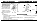
30, 60 & 100 AMP PIN & SLEEVE MECHANICAL INTERLOCK
6.87
[174.50]
4.75
[120.65]
10.12
[257.05]
7.75
[196.85]
8.00
[203.20]
11.00
[279.40]
6.87
[174.50]
4.75
[120.65]
11.87
[301.50] 9.75
[247.65]
12.75
[323.85]
7.75
[196.85]
MOUNTING FEET
ADJUST TO ANY 1
OF 3 POSITIONS
CONDUIT HUB
•
•
•
UNIT RATING •
•
•
•
GROUNDING
(BONDING)
PLATE
•
FIG. M1 • 30 AMP FIG. M2 • 60 & 100 AMP
BOTTOM FEED
(RECOMMENDED METHOD OF ENTRY) OPTIONAL
CENTER
LOCATION
FOR 3 POINT
MOUNTING
A.Mounting Instructions:
1. This enclosure must always be mounted vertically with receptacle end down.
2. This enclosure may be mounted for top, bottom or back conduit entrances. Bottom feed is recommended whenever
possible. Figs M1 & M2. Back feed is permitted in Type 4X applications only. Fig. M4.
3. For Type 4X and Type 12 applications, enclosure must be mounted by means of mounting feet. DO NOT drill, punch or
nail mounting holes through the enclosure.
4. Mount the feet to the enclosure using the screws provided. Tighten to 10-12 lb•in (1.2 - 1.4 N•m).
5. Mounting feet will accept up to 5/16 inch (8 mm) diameter screws (not provided). Mounting pattern is shown in Fig. M1.
6. Remove the four (4) cover mounting screws and remove cover. Switch handle must be in “OFF” position to remove cover.
7. Drill or punch hole at the desired conduit entry location:
a. 1-3/8 inch (34.9 mm) diameter for 1 inch trade size conduit hub (30 Amp).
b. 1-3/4 inch (44.4 mm) diameter for a 1-1/4 inch trade size conduit hub (60 & 100 Amp).
Molded drill spots on the outside top, bottom and back surface show the locations. Fig. M4.
8. Use ONLY Listed/Certified conduit hub rated for Type 4X and Type 12 applications (one supplied) such as:
RACO #1704 for 1 inch trade size (30 Amp)
RACO #1705 for 1¼ inch trade size (60 & 100 Amp)
9. Install the conduit hub. Be sure that the “O” ring is properly seated in its groove.
10. Install the grounding (bonding) plate under the conduit nut. Tighten nut securely for a watertight seal and grounding continuity.
11. Any unused conduit entrance holes must be sealed with Listed/Certified closure plugs rated Type 4X and type 12. (Hubbell
Cat. No. MICPK30 for 30A, Cat. No. MICPK60 for 60A and 100A).
12. NOTE: The metal closure plug must be grounded (bonded) back to the inside green & yellow grounding buss. Grounding
(bonding) wire connection required.
13. Use of user-installed conduit entrances above the switch are not recommended in applications where condensation may be
present in the conduit (high humidity and extreme temperature change locations). When using the top feed conduit entrance,
drip loops must always be formed as indicated in fig. M3.
INSTALLATION INSTRUCTIONS
Dimensions in inches [mm]
HUBBELL CIRCUIT-LOCKTM
U.S. Patent No. 5,298,701 English

PD1788 (SHEET 1 of 3 • PAGE 2) PRINTED IN U.S.A. 8/06
CAT. NOS. AMPS RATING HORSEPOWER USE PIN & SLEEVE WIRE
[kW] PLUG CAT. NO. PER FIG.
HBL330MI4W 30 120VAC 2 [1.5] HBL330P4W W1
HBL330MI6W 30 240VAC 3 (208-240VAC) [2.25] HBL330P6W W2
HBL330MI7W 30 480VAC 7.5 [5.62] HBL330P7W W2
HBL430MI5W 30 600VAC 3Ø 20 [15] HBL430P5W W3
HBL430MI7W 30 480VAC 3Ø 15 [11.25] HBL430P7W W3
HBL430MI9W 30 240VAC 3Ø 7.5 [5.62] HBL430P9W W3
HBL430MI12W 30 120 / 240VAC 3 (208-240VAC, L-L) [2.25] HBL430P12W W4
HBL432MI3W 32 380VAC 3Ø 50 Hz 15 (440VAC 3 Ø 60 Hz) [11.25] HBL432P3W W3
440VAC 3Ø 60Hz
HBL530MI5W 30 347 / 600VAC 3ØY 20 [15] HBL530P5W W5
HBL530MI7W 30 277 / 480VAC 3ØY 15 [11.25] HBL530P7W W5
HBL530MI9W 30 120 / 208VAC 3ØY 5 [3.75] HBL530P9W W5
HBL360MI4W 60 120VAC 3 [1.5] HBL360P4W W1
HBL360MI6W 60 240VAC 7.5 (208-240VAC) [5.62] HBL360P6W W2
HBL360MI7W 60 480VAC 20 [15] HBL360P7W W2
HBL460MI5W+ 60 600VAC 3Ø 40 [30] HBL460P5W W3
HBL460MI7W 60 480VAC 3Ø 30 [22.5] HBL460P7W W3
HBL460MI9W 60 240VAC 3Ø 15 [11.25] HBL460P9W W3
HBL460MI12W 60 120 / 240VAC 7.5 (208-240VAC, L-L) [5.62] HBL460P12W W4
HBL560MI5W 60 347 / 600VAC 3ØY 40 [30] HBL560P5W W5
HBL560MI7W 60 277 / 480VAC 3ØY 30 [22.5] HBL560P7W W5
HBL560MI9W 60 120 / 208VAC 3ØY 15 [11.25] HBL560P9W W5
HBL3100MI4W*100 120VAC 5 [3.75] HBL3100P4W W1
240VAC 15 [11.25]
HBL3100MI6W 100 208VAC 10 [7.5] HBL3100P6W W2
HBL3100MI7W*100 480VAC 30 [22.5] HBL3100P7W W2
HBL4100MI5W 100 600VAC 3Ø 50 [37.5] HBL4100P5W W3
HBL4100MI7W 100 480VAC 3Ø 50 [37.5] HBL4100P7W W3
HBL4100MI9W 100 240VAC 3Ø 25 [18.75] HBL4100P9W W3
HBL4100MI12W*100 120/240VAC 15 [11.25] HBL4100P12W W4
208VAC 10 [11.25]
HBL5100MI5W*100 347 / 600VAC 3ØY 50 [37.5] HBL5100P5W W5
HBL5100MI7W*100 277 / 480VAC 3ØY 50 [37.5] HBL5100P7W W5
HBL5100MI9W 100 120 / 208VAC 3ØY 20 [15] HBL5100P9W W5
LWG
N
L1 L2 L3
T1 T2 T3
N
GREEN/YELLOW
GROUNDING
(BONDING)
PLATE
GROUND
BUSS
(GRN/YEL)
•
NEUTRAL
BUSS
(BLUE)
•
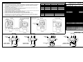
2 POLE 3 WIRE
SINGLE PHASE
FIG. W1
G
GGROUND
BUSS
(GRN/YEL)
•
GREEN/YELLOW
L1 L2 L3
T1 T2 T3
2 POLE 3 WIRE
SINGLE PHASE
FIG. W2
GROUNDING
(BONDING)
PLATE
L+ L1
L2
L3
L1 L2 L3
T1 T2 T3
LLG XYZG
GREEN/YELLOW
GROUND
BUSS
(GRN/YEL)
•
G
GROUNDING
(BONDING)
PLATE
3 POLE 4 WIRE
3 Ø
FIG. W3
LLG
W
NG
L1 L2 L3
T1 T2 T3 •
NEUTRAL
BUSS
(BLUE)
••
NEUTRAL
BUSS
(BLUE)
•
GROUNDING
(BONDING)
PLATE
GROUNDING
(BONDING)
PLATE
GREEN/YELLOW
GREEN/YELLOW
L1
L2
N
3 POLE 4 WIRE
EDISON SYSTEM
FIG. W4
GROUND
BUSS
(GRN/YEL)
NG
L1 L2 L3
T1 T2 T3
L1
L2
L3
N
XYZ
WG
FIG. W5
4 POLE 5 WIRE
3 Ø Y
B. Wiring Instructions
1. Select conductors having 90°C or higher rated insulation and sufficient ampacity in accordance
with the 60°C column (for 30 Amp and 60 Amp devices) or the 75ºC column (for 100 Amp
devices) of the National Electrical Code® Table 310-16 or Canadian Electrical Code Table 2.
2. CAUTION: USE COPPER CONDUCTORS ONLY.
3. DO NOT TIN CONDUCTORS.
4. Make sure the connected equipment rating does not exceed the rating of this device. See
General Information #4 regarding overcurrent protection.
5. Terminal capacity as indicated in Table 1
6. Strip conductor insulation ½ inch (13 mm).
7. Select proper wiring diagram. Loosen terminal screws. Insert conductors fully into proper terminal.
8. Tighten terminal screws to torque indicated in Table 2:
9. TAKE CAUTION THAT THERE ARE NO STRAY WIRE STRANDS.
10. Tighten the grounding buss mounting screw to 10-12 lb•in (1.2-1.4 N•m).
11. Reinstall the cover. The handle must be in the OFF position. Make sure the rope gasket is
properly seated in the groove. Tighten the four cover screws to 10-12 lb•in (1.2-1.4 N•m).
12. Consult factory for auxiliary contact availability.
INSTALLATION INSTRUCTIONS (CONTINUED)
•
30 AMP 60 & 100 AMP
FIG. M4 • BACK FEED
(TYPE 4X INSTALLATIONS ONLY)
•
GROUNDING
(BONDING)
PLATE
MOLDED IN DRILL POINT
(ONE TOP, ONE BACK,
ONE BOTTOM) •
•
FIG. M3 • TOP FEED
30 AMP 60 & 100 AMP
GROUND
BUSS
(GRN/YEL)
PROVIDE
CONDENSATE
DRIP LOOP
AS SHOWN
THIS DEVICE CARRIES A MAXIMUM RATING OF:
GGGGG
WIRING DIAGRAMS
* Consult factory for availability
30A 60A 100A
Switch #4 to #12 AWG #2 to #10 AWG #2 to #10 AWG
Ground #6 to #16 AWG #4 to #10 AWG #4 to #10 AWG
Neutral #8 to #22 AWG #4 to #14 AWG #1/0 to #14 AWG
Auxiliary
contact #14-18 AWG #14-18 AWG #14-18 AWG
TABLE 1
30A 60 & 100A
Switch 27 lb•in (3.0 N•m) 50 lb•in (5.7 N•m)
Ground 16-18 lb•in (1.8-2.0 N•m) 22 lb•in (2.5 N•m)
Neutral 13-15 lb•in (1.5-1.7 N•m) 22 lb•in (2.5 N•m)
Auxiliary 10-12 lb•in (1.2-1.4 N•m) 10-12 lb•in (1.2-1.4 N•m)
contact
TABLE 2
Pilot 20 lb-in (2.5 N•m)
Pilot #12-18 AWG P12-18 AWG
Pilot contact (if installed)
-
 1
1
-
 2
2


Hubbell Wiring Device-Kellems PD1788 Installation guide
- Type
- Installation guide
Ask a question and I''ll find the answer in the document
Finding information in a document is now easier with AI
Related papers
-
Hubbell Wiring Device-Kellems PD2139 Installation guide
-
-
-
-
-
-
-
-
